Leaderboard
Popular Content
Showing content with the highest reputation on 02/13/2020 in all areas
-
The project has been completed, so it's time for the gallery. The model was made of prototype moldings. Thanks to the cooperation with Yahu and Master, I was able to equip the model with add-ons that these companies will offer to valorise this aircraft (dashboards, rifles, Venturi tube). I made some elements myself: cables, propeller blades, wing container for ammunition and elements of the inside of the wing). I painted the model with Bilmodel Makers and Hataka paints. The markings were made using masks of our own production (thanks Marco). Photos of the first test model and workshop can be viewed here: I invite you to watch.11 points
-
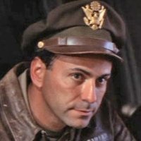
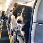
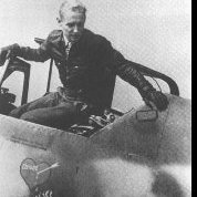
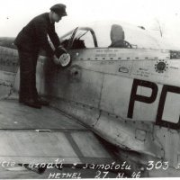
Thanks for the comments guys. Two things that I am not overly keen on doing with models are seat belts and brake lines. For some reason I find this stage of the build to be a bit of a pain! Needless to say, they both need to be done. First up, the brake lines on the undercarriage. The kit has some reasonably nice lines already there but they are moulded integrally with the leg and are a little to 2D for my liking. I sanded them off. I used .4mm lead wire and .4mm copper wire to depict the two lines that run up each leg. I used thin aluminium foil to replicate the brackets that hold each line in place. A very thin strip of it was passed behind the lines and then folded back up itself. I used the excellent RP Tools ring maker to fabricate some tie down rings. These replaced the kit tie down points which are just lumps of plastic as can be seen by the unmodified one on the left. Done. I hate using photo etch seatbelts, so I used the Aires photo etch and resin buckles and made my own belts from thin aluminium foil. The shoulder straps were next, I used a small section of copper wire at one end to allow me to roll the end over and form the attachment loop. as can be seen on the top strap. Looking at my reference pics, I noticed that on some of them, the pilots shoulder straps were hung over the side as can be seen in the following pics. An excellent pic (not Ron) of a pilot about to go flying. His helmet is on the windshield and the shoulder straps are just visible, hung over the side. Another pic of a maintenance scene. Same deal with the shoulder straps. I thought that this would be a great feature to incorporate, it would really give the model a human touch. I got in touch with Ron and asked him about what the protocol was when the pilots were about to go on a sortie. Here is his response: Typically, when we went out to the aircraft for a mission, we would mount the ladder and deposit our parachute into the cockpit and place our helmet on the top of the front windscreen. We would then dismount and conduct our preflight inspection of the aircraft. Upon completion of the preflight, we would go up the ladder and get into the cockpit. The crew chief would come up the ladder to help us strap in and it was typical for them to leave the straps hanging over the cockpit rail so that this would be easier to do. So -- short answers to your questions are - helmets were placed on the front windscreen until we put them on, and the safety straps were left hanging over the canopy rail until the chief helped us put them on. The photos you sent were authentic. Hope this helps you. Ron Based upon the pics, and Ron's great reply, I got to work and made it happen. I made a copy of the Aerobonus F-100 pilots head with helmet and carved out the head. This will be painted as per the pics that Ron supplied earlier in the thread with his name and checkers on it..... if I can paint them that small! The objective will be to draw the viewers eyes into the cockpit. Just need to work out the parachute pack.11 points
-
Thanks for the support, much appreciated!! Well the nice thing about a model with six million parts is that if you bugger up one part there's enough separate sub assemblies that are kits in themselves to keep a modeller (and me) moving along. I figured I could take a bit of a break from fixing my accident and move along to this... I painted the "plywood" walkways with Vallejo dark flesh and drybrushed/ wet washed with Vallejo wood for grain, then gloss clear, then, chipping medium and Tamiya rubber black then weathered it. Thanks for looking11 points
-
Aeromarine 75/Curtiss F-5-L (Finished)
Starfighter and 9 others reacted to kkarlsen for a topic
Yesterday the Wingnut Wings Fans 10 year Anniversary group build was decided... I'm very thankful to Wingnut Wings for picking my 'Aeromarine' entry, there were so many wonderful builds participating. Richard Alexander said: "Everyone really loved looking through the entries and it was very (very) difficult to choose our top three. Not everyone agreed with other peoples choices but I think in the end we all agreed that these are very worthy entries. The top 5 models were very close indeed with the exception of the amazing Aeromarine conversion which almost unanimously everyone's 1st place choice. A BIG thank you! to Richard Alexander and Wingnut Wings for this recognition of my work! Cheers: Kent10 points -

ICM Gladiator slow build. Finished!
Paul in Napier and 9 others reacted to quang for a topic
A quick snap in the wee hours of the mornin’.10 points -
HH-60G Pavehawk Kitty Hawk 1/35 DONE!!
KiwiZac and 9 others reacted to Pete Fleischmann for a topic
Mostly done with the ceiling. There are a bunch of cables and comm cords to run still, but I’ll have to wait on those- moving forward to the cockpit overhead panel next- cheers Pete10 points -

A6M7 Model 62 1/32 Hasegawa
corsairlada and 8 others reacted to Miloslav1956 for a topic
A6M7 Model 62, 302 Kokutai Model Hasegawa 1/32 HGW rivets, wet transfers, seat belts & mask Eduard wheels All colour MRP test set IJN Marking mask home made9 points -
Time to resurrect this build from the SoD - inspired by Wackyracer's fabulous PR XI build. My SLA printed F.24 cameras finally arrived. Well, I had to switch to a professional 3D printing service which was quite expensive but defintely worth the money! Have a look mates: Keep in mind that those cameras aren't bigger than 1cm! I have to look into my cockpit for some modifications regarding the camera control and the bigger issue: the mounting frame for the camera. Cheers Joachim8 points
-
Hi Rob (and others this may pertain to!), My sincere apologies for not replying. In your case Rob, I really thought I did (and wondered why you didn't e-mail requesting an invoice). To answer your question, yes the A-7 intake corrections are available, as are all other items on my website. Any items not available have either been removed from the website or are listed as currently not available. The past few months have been my busiest in my near 15 years of running Zactomodels. As Seiran mentioned, I'm a one-man-band and sometimes in the chaos things get missed. Yes, sometimes life gets in the way. I do try to reply to all e-mails but when things get hectic and the inbox gets flooded it can be difficult. I try to always reply to order/business related e-mails first and get to the others when I can, but sometimes they get buried and forgotten. If something you consider urgent hasn't received a reply, please re-send it. Family issues happen with everybody and family always comes first. Maintaining a 90 year old house and its contents can also be a challenge. The good news is that there's not much left that can break (knock on wood) that I haven't repaired. And then there's Mother Nature... While Preston Idaho doesn't get an overwhelming amount of snow, I have a two-car wide 120' driveway and I'm armed with nothing but a shovel. Not fun when you have a bad back. Add in having to shovel doggie trails in a big back yard and the result can be slowed down work and necessary recovery time. As mentioned, I've been busier than ever. I do my best to get the orders out as quickly as I can. Normally this would be the next or following day, but lately it's been 2, 3 even 4 or more days depending on the line. If the delay is longer than a few days I always try to contact the customer and let them know the status of their order. A huge "Thank you!" to all that have been supporting the business. It is much appreciated (and much needed!). Cheers, Chris8 points
-
Mike, Brian, thanks for the support! Mike, the stand is from JHModels; they have their own site - jhmodels.eu - but I think I sourced mine via modellingtools.co.uk It's a biplane stand (with only two of the four supplied arms fitted) and they do two sizes; this is the larger one for 1/32 and up, the other is for 1/48 or 1/72. It comes as a laser cut wooden kit that you have to assemble. Not overly robust but works nicely. --- Final post! I was going to post yesterday but in between firing ImageShack up and uploading the pics I took of working on the antenna, I was distracted by a long rambling phone call and then deleted them by mistake so I went to the pub for a sulk instead. You'd think my time in the IT industry as a nipper would have taught me to back everything up before doing anything irreversible - apparently not, lol. Oh well. One pic survived, ironically because I wasn't going to use it: To précis: using 1mm styrene card, mark rough mounting shape with Sharpie then carve with various knives, files and sanding sticks. Add 0.3mm hole to take the antenna, which is 0.3mm rod inside 0.5mm tube (see above), glued with a smear of CA on the "inside" end of the rod. Progressively trim the excess 0.3 to fit the depth of hole previously drilled and connect with a further tiny dab of CA. Touch of white paint and satin varnish, further tiny dab of CA to attach it to the model, and presto. Worked a treat (eventually ... what you see is attempt number four), if a bit oversize - it theoretically ought to be 17.78x11.25mm overall, mine came out at 18x13ish, and the mount looks more like a Comant than a RAMI (bit taller and thinner) ... but if I don't tell you, you won't notice the difference And so, herewith the final pic! This build has served its main pupose, in that I've learned a lot, and most importantly has been fun. I'll post in the RFI forum next week, once I have a decent backdrop to use - but for now, thanks for watching and for the kind words and support! Sepp, out.7 points
-

1/32 MH-53E Sea Dragon - 3D printed / scratchbuilt
Dadeo911 and 6 others reacted to Starfighter for a topic
I am hugely motivated to work on my models since quite some time, but few things are going to plan at the moment - the reappearing cracks on the Skywarrior drive me nuts and the air intakes of my resurrected , heavily modified Revell Tomcat are fighting me with all their force. This and the arrival of the aluminium sheet I ordered some time ago led to the decision to give skinning the MH-53E a go. I have probably chosen a pretty difficult area to start with, but it helps to get a feeling how to cut and sand the resulting panels. The biggest problem I face is not necessarily cutting the templates and the panels, but the riveting. The MH-53E is covered with thousands of raised rivets which I am not sure how to do. The tools I have do not seem to be suited to this task (and believe me, I have tons of riveting tools...). I am not a huge fan of riveting wheels as they don't offer enough control IMO, metal tips go through the material, the blunt ones I have are too thick, etc. Then, it does not seem to be possible to properly sand the panels with the raised rivets added, so they don't look crisp enough. As scribing the material - which would be my preferred option - does not work as intended, I am currently thinking about several options: - skinning the model but using decals for the rivets - making templates, scanning them, redraw them on the pc, add rivets and have them photoetched. HPH uses this method to do the (raised) surface detail of their models. The problem I see is that the scanning and redrawing process adds more possible sources for mistakes and inaccuracies and I have to admit I am not really in a mood for hours of trial and error. As you can see, I am in the mood to build and to make progress, but it's not that easy. Any hints or tips would be appreciated...7 points -
Got the last bits onto the Aires cockpit tub including the HGW harnesses. The sidewalls are glued into place. Once that is done, the cockpit details get swallowed up into what is probably one of the most claustrophobic cockpits of any WW2 fighter plane.6 points
-

Finished !!! 1/32 Revell Junkers Ju-88A-1
Victor K2 and 5 others reacted to Tolga ULGUR for a topic
Replacement parts from MDC arrived safely and nstalled.. Gun barrels are from Master-Models #32013 I have used Profimodeller pitot tube before finishing this large bird. More pictures will be posted in RFI section later. PS: By the way I am looking for "desperately" another Corrected tail and rudder set for my Ju-88A5 project . This set was out of production long time ago.6 points -

KH T-6/Harvard Kicked Up A Notch: Apr 14/20: Finished!
Greg W and 4 others reacted to chuck540z3 for a topic
Feb 13/20 A small update, but I think an important one. Putting together the front cowl, I recall that Max (Mozart) was complaining about it in his build and now I know why. The cowl on the real deal comes in 3 roughly equal parts that are connected together with an obvious band of fasteners, with one on the top and the other two equidistant away, sort of like the Mercedes Benz symbol. Instead of utilizing these obvious joins, Kitty Hawk used none of them and made the cowl out of 4 parts, where all joins should be filled. Dumb. Even if they needed to make the cowl out of 4 parts due to curvature and size restrictions, they could have used at least two of the cowl joins instead. Also, that oval notch on the right should be cut out to accommodate the exhaust, which the instructions never mention. Here is the finished cowl, with the seam lines filled with CA glue and a band of spare brass for the top join, which the kit omitted and is close enough to the other two joins on the sides. Although the fasteners are not the correct spacing, they look the part with a fastener on each end, which was lucky. Another dumb Kitty Hawk design is that there are only 3 taps to hold the cowl in place and they aren’t evenly distributed, like the one on the lower left inside the cowl. It works OK despite this oversight, but 4 tabs would have been much better. Here you can still where the joins were filled with clear CA glue, as was the little square anchor point for a front mast, which my subject doesn’t have. Another weird feature of the cowl, but from Eduard this time, is extensive brass detail within the cowling, which you will never see with the engine installed. Even if the cowling was left off, it would naturally be in 3 parts, so I don’t know why Eduard bothered to create these PE parts, which I left off. After reviewing many reference photos, the position of the top band should be slightly offset to the starboard side, with the port side edge roughly the center line. I bet I get a deduction at a future model contest for a crooked cowl. Lol, I don’t care….. Getting the cockpit ready to be sealed up before painting, I added the windscreen and rear canopy parts, which reveals that the rear canopy is also too narrow, presumably to fit the narrow canopy parts. Even the AlleyCat replacement canopy part that Max used is narrow as well, because it needs to fit the fuselage that is made for this part. This tells me not worry about the width of the canopy parts anymore, because even if I did manage to get stretch them wider, the rear part wouldn’t fit the rear canopy, so it’s better off if left alone. As a result, I am going to place the 3 overlapping canopy parts in the middle and call it a day, just like everyone else! That will be it for progress for a while, as I head south for warmer climes for a few weeks and some much-needed R&R. When I get back, this bird will be hitting the paint barn as I finish off other small details. Cheers, Chuck5 points -

Zvezda Star Destroyer - a new detailing project
Greif8 and 4 others reacted to The Madhatter for a topic
Thanks for the tip Neo - I'll try to remember that when I get to it So, I have managed to get most of the starboard sidewalls and roof parts detailing done with only 3 left to go. Then it'll be time to blend in the walls to the surface and add some other stuff around - then the last part of the top side surface detailing will be over. I'm still deciding if I will paint first then add the fiber or vice versa. I'm leaning toward paint first because I just think it'd be too hard to be able to trim off fibers without damaging the paint work but shuddering at the thought of how much time it'll take to do it like that. No pain no gain right? Anyway, here's some pics of where I am at currently That's it for now, but as always, thanks for stopping in and having a look Si5 points -
Here is my recently completed 1/32 Tamiya F4U-1a Corsair painted in one of Greg "Pappy" Boyington's purported mounts, BuNo. 17740. The Tamiya kit is an extraordinary state-of-the-art kit and doesn't need much to build up into an impressive model but I did take the liberty of adding a few aftermarket items: 1. Vector Resin Cowling 2. Barracuda Resin Wheels and Tires 3. HGW Fabric and Phototech Harness 4. Barracuda Cockpit Stencils 5. Montex Masks 6. True Details Resin Parachute 7. HGW Wet Transfer Stencils The complete build can be found here: The canopy is removable so that I can pose it in the closed or open position. I did not glue the wings into place so that transport would be easier. AK Real Colors acrylic paints were used for the exterior.4 points
-

Another Goldfinch!!
Alain Gadbois and 3 others reacted to mozart for a topic
Whilst I was thinking about the forward end, I thought I'd fit these "nail clippings", the louvres for the vents I guess. They ping off all over the place if you're not very careful!4 points -
Hi friends Today next step ! I think i never finish this one Glue........piece of grass and more piece of grass. Glue some elements and bridge gaps with.......grass Marking slabs. I put more tree! Tomorow i paint the small guys.4 points
-
I didn't even realise until you made me look closer Unfortunately i don't think removing this at this time would be a good idea. This windscreen is really a nightmare Painting started with specific areas coated in MRP silver metallic . Then 3 light coats of MIG scratching effects to allow chipping at further stages: As a sidenote, notice the effect of sanding the front of the windscreen when the canopy is closed. The underside were given a preshading in black and was then painted with MRP Medium Sea Grey (I didn't mask the wheel wells, I haven't decided if they should be left interior green or medium sea grey) Topside, I started with the MRP Ocean grey following pattern A: I usually paint the camouflage freehand but this time I decided to have a try at hard edges and scalled pattern A with paper masks to protect the grey before spraying MRP Dark Green This provides the base for further fun. (All the previous work was made to get here and start enjoying the painting and weathering process4 points
-

Caudron C.714, Azur, 1:32
R Palimaka and 3 others reacted to Landrotten Highlander for a topic
4 points -
More progress on the engine, it needs to look like this: All 14 spark plugs are in place, very happy with the way they have fitted so now I'm thinking about the other "plumbing": So this this the end product: most of which won't be seen anyway! Flip it over to the front: I've pre-drilled the seating holes for the connecting rods on the engine block, just need to clean up the under surface of the valve covers then spend the afternoon delicately placing the connecting rods.4 points
-
Well I am still at it, the yellow flash mask on the starboard side was removed and the yellow extended, it's a good job Mal sent extra masks for me, then it was time to apply the masks to the tail which I had already airbrushed white. The mask was cut down to size and the position for it was marked on the tail with Tamiya tape, transfer tape was applied to the mask to hold it all together and the mask applied, this was the tricky bit that I was not looking forward to but it worked. The transfer tape and the masks was removed to reveal this The Tamiya tape on this side was used as a guide to mark out the other side of the fin/rudder Then the flash mask was re applied to the fuselage side where the yellow had to be extended, to do this the mask was held together with Tamiya tape while I applied it. With this all done I was now ready to start the paint job, my wife wanted to know how I was getting on so I showed her what I was doing, during which I noticed this. Stupid boy, so the masking was removed and the white extended, once again it was a good job that Mal sent me spare masks. Cheers Dennis4 points
-
In order to represent any kind of stained appearance, you really need to do it over a matt surface. This actually replicates the real world mechanics of the staining process, by allowing the wash to literally stain your matt/flat coat. Just be warned, though: it's an unforgiving exercise, and if you don't like the result, you'll probably have to paint over it! Here's an example from my Corsair build: Kev4 points
-

PR.XI & Mk.Vc - Revell Mk.IXc & Mk.IIa kits
VW Chris 1969 and 3 others reacted to Wackyracer for a topic
only added a few more bits n bobs to the pit at club night Added the camera trigger to the stick4 points -
I was showing this to my wife just now....she says my gawd all you guys are nuts! I’d take that as a compliment!4 points
-
Ok sorry for the delay as real life sometimes gets in the way. I’m still working on decals so here’s an in-progress look: Decals on the left side. The decals are thick and do not adhere well all of the time. Soaking decals (especially the walkway lines) in Solvaset isn’t helping much. I’m repeatedly poking holes in them to try and get more setting solution to pull them flat: Left forward fuselage. You can see the thickness of the decals if you look at the aircraft number: Left side of the rudder. Again, the “Armee De L’Air” decals are fighting every application of setting solution: My conclusion - if you have access to replacement decals then by all means get them. I wasn’t prepared to spend $40 plus shipping to get an untested brand from France on eBay. I’m hoping that an established company puts some decals out for the -D before too long. John4 points
-
the finish line is coming into sight! landing gear in primer tails finished: weapons pilons: flaps: removable armament: just a few more weekends!4 points
-
HH-60G Pavehawk Kitty Hawk 1/35 DONE!!
KiwiZac and 3 others reacted to Pete Fleischmann for a topic
Almost there.... cheers Pete4 points -
Kitty Hawk 1/32 Mirage 2000B/C/D & N
Jack and 2 others reacted to thierry laurent for a topic
Domino got them two weeks ago. There are indeed two Greek schemes including one with a huge tail art.3 points -
WiP with the conn rods: And all nicely in place: Fitting the ignition leads will quite a tight fit with the collector ring: I've ordered three different sized packs of plastic tubing for the ignition leads, hoping these will do the job.3 points
-
Caudron C.714, Azur, 1:32 - FINISHED
Tnarg and 2 others reacted to Landrotten Highlander for a topic
I consider the kit completed. Here the link to the topic on the RFI forum. A bit wobbly while taking the picture, but this close-up of the office does show the effect of painting the inside of the glass on the inside and the outside on the outside (for a smaller scale I just painted the 'inside colour' on the outside of the cockpit before painting the camouflage). What I like about this approach is that you get an increased sence of glass being encased in a framework. Some thought about the kit - the basic building blocs are good in shape nd general fit, however, some of the details are not entirely correct. I am now considering making another verwion of this plane - this time with the Polish forces in France - but working out all the (minor) errors in the kit. We will see. Thanks for all who followed , commented and liked. Slainte ghu mhath L.H.3 points -
PR.XI & Mk.Vc - Revell Mk.IXc & Mk.IIa kits
LSP_Kevin and 2 others reacted to Wackyracer for a topic
some days are better than others3 points -
2 questions Zacto and G Factor
Michael931080 and 2 others reacted to Out2gtcha for a topic
At least its nice to know that one of our most liked vendors is doing steady/good business! I think I speak for most Chris when I say your products are thoroughly fantastic, and top notch in about every way you can categorize "top".3 points -
Well that last one made me laugh! Yes the model is definitely repairable, all the breaks were on glue joints, thank goodness! One of the pilots left his seat and lost his head, I think that was probably the only really bad break. Some locating pins to align bulkheads were broken off in their receivers as well but setting the parts in place in the fuselage should align them as well. As suggested above, I'll leave it for a day or so but I'm anxious to repair the damage and get myself back on track. Not the first time for something like this with me, I once dropped a 1/32 Ju 88 as I was placing the last decals. I blame 30+ years of auto repair and impact tools for numb hands! I also once hooked the wing of a (again, 1/32) B-25 with my elbow and knocked one side off the bench, thank goodness HK Models knows what they're doing with their landing gear, that one stayed (mostly) together. All models were eventually completed I should be back on track in a day or so...maybe three?3 points
-
Ju-87B, 1:32, Trumpeter
mywifehatesmodels and 2 others reacted to Hartmann52 for a topic
3 points -
Flaps are done! I used the kit flaps, thinned them down a bit and cut a bit off each end, then glued thin sheet styrene to both sides, overlapping the ends to the original length. Sanded the trailing edge almost to a knife edge, then primed, RLM 65 overall w/ wood (Testors 1735)on the top surface, and then some transparent woodgrain decals from HGW. This was my first attempt with the decals, and I found them VERY soft and hard to use without ripping them, even doing each piece individually so the grain doesn't align across the joints. I wound up having to spray a thin clearcoat over them while still on the paper to give them some strength. That worked fine for decals going on a flat surface, but I'm not sure what I would do for a curved one! I overlapped the edge of the decals at the joints slightly to form the dark glue lines, then accentuated them a little with a burnt sienna pencil after the matte clear was dry. Here are the real flaps: Tim3 points
-

1/32 Tamiya F4U-1a Corsair - Boyington's 17740
Loach Driver and 2 others reacted to Thunnus for a topic
Thank you Rod and Brett! Here are some more photos...3 points -

1/32 Trumpeter F-14A Tomcat
Greg W and one other reacted to Mark Jackson for a topic
I keep on hearing the voice of donkey from Shrek singing, "Back on the road again..."2 points -
I actually am the one who procured (or should I say received here) Peters litho plate for him. Did you want me to look and see the "brand" as it were, or where it came from if that might help?2 points
-
1/32 MH-53E Sea Dragon - 3D printed / scratchbuilt
HerculesPA_2 and one other reacted to Starfighter for a topic
Mark & Thierry, thanks for your input! The problem is that the Micromark rivets are much less consistent in shape compared with the Archer ones - this sadly is only visible under a coat of paint. I have used a few meters of both and I'd prefer to use Archer rivets. I've been thinking about the model the whole day and I haven't come to a conclusion yet. If I can manage to translate the templates into perfectly shaped panels in my drawing program, the result could be absolutely perfect surface detail... Mark, the idea sounds great but printing onto decal film sadly isn't possible, at least with my printer.2 points -
thank you jimbo2 points
-
PZL P.11c 1/32 IBG Models
LSP_Kevin and one other reacted to R Palimaka for a topic
For a minute there, I thought Kev had learned to speak Polish! Richard2 points -
How do you make believable oil stains?
D.B. Andrus and one other reacted to thierry laurent for a topic
Another technique that is rarely used is the one relying on the darkened base color. If you look at pictures, you will see that stains and dirt sometimes color the surface but very often simply darken its color. Accordingly, you can make quite accurate stains with spots of hand painted diluted paint based on the base color darkened with a very little bit of black. This is what I recommend for the initial dirt coat. And then, if relevant, you can add other stains, splashes, drops and so on with a more or less transparent color that may be brown, orange, black, blue or any other valid color reproducing the fluid according to the type, purity and considered era. This is quite easily done with heavily diluted oil paints but enamels can also be used. There are also some specialized acrylics such as Lifecolor Tensochroms but their storage life is quite short whereas oil paint tubes can be stored for decades. Finally, as already written, this is far more efficient on a flat or at least a satin base (any other aircraft modeller who is also an AFV modeller will confirm it). On a gloss one, an efficient technique asks for the use of the airbrush and masks but I do not recommend that except for planes such as shiny warbirds or airliners. And in that case, this should be very subtle to simulate some discoloration or darkening of the paint rather than actual dirt.2 points -

Cross kitting Tamiya F-4C and Revell RF-4C
thierry laurent and one other reacted to Tony T for a topic
Personally I would not. The RF-4 fuselage under the cockpit has a straighter, more boxlike profile due to the SLAR cheeks, so the Avionix horizontal line will produce the right profile. Tony2 points -
OK, now when I nod my head, you hit it Richard2 points
-
Nice surface. With all of that being said, your option is decals as rivets. You'll never gain the rivet dome by reverse imprinting any material. If you do templates, you can do a rivet decal sheet for simple surfaces and individual lines for complicated surfaces. I'm sure Archer Decal, or someone, would do them for you. Anything can be gotten for a price. Sheets would save you some time over individual lines of rivets. Just my take. Good luck. Sincerely, Mark2 points
-
Got an email from Simon at Silver Wings and with a pre-order discount, and discounted shipping I couldn't resist her............ Depending when I can actually get back to the bench and finish my Ki-45, This lovely lass may be on the bench next...............just need some MRP WWII RAF yellow.2 points
-
Thanks guys. Yes, it saved around half the weight. I figured that the model has to lug them around for a long time so I may as well have made them lighter. Some more work. I added the Aires photo etch rivet detail to the inside front frame of the canopy, and used lead wire to simulate the round tubing which is attached to it. I really wanted to simulate the weld beads all over the tanks. I filled all engraved panel lines except for the major joins, and then taped up each bead. Using a paint brush, I dabbed Mr surfacer brown over each line. I repositioned the front filler caps onto the left side of each tank. A hole was drilled, then a circle scribed around each one, before a disk of plastic card was inserted into each one to depict the filler cap. The rear fins were modified from the kit ones by sanding them so they were much more swept back. I also added the rear filler caps using the same process as above. The two finished tanks. Much work has gone into these! Under a coat of paint, the welded seams look good. The front of each of the tank pylons should be curved inward. To accomplish this, I made a few small cuts. I used chipping fluid to apply a bit of weathering to the front of each tank. Still not sold on the idea. Visible in the pic is some modification happening to the inner pylons, with new sway braces. Ore on that later. Where the jet sits at the moment. Lots to do but getting there.2 points
-
I've decided I better add more "stuff" visible inside the fuselage if I'm going to make any large damage injuries allowing seeing into the model, Control cable runs in progress; Thanks for looking2 points
-

1/32 Tamiya F4U-1a Corsair - Boyington's 17740
Bobs Buckles and one other reacted to LSP_Kevin for a topic
What a fantastic build, John! One of the most impressive Corsair models I've seen. May I publish it on the website? Kev2 points