Leaderboard


Popular Content
Showing content with the highest reputation since 06/18/2025 in all areas
-
my last built :39 points
-
Hey everyone! So, for a change, here's a Bf 109 G-6 in 1/35 scale from Border Model. Honestly, I think it’s the nicest large-scale version of this plane out there, I couldn’t get my hands on a 1/32 kit, no shop had any in stock. This Border Model kit is really great: it’s got the right shape, very accurate, packed with details, and super easy to build. The only real issue is the decal sheet, it's mostly incorrect and doesn't even include decals for the instrument panel. So I picked up an IP and some pilot harnesses from Eduard. As for the decals, I tried an aftermarket sheet, but it turned out to be even worse than the one from Border Model… Thankfully, my Silhouette Cameo saved the day. The only decals I actually used are the yellow "87" triangle on the left, the stencil under the exhausts, and the round stencil in front of the "1" on the right. Everything else was done with masks: the 8 crosses, the '1', the "-", the JG53 emblems, the victory marks on the rudder, the little red triangle on the left just behind the spinner, the manufacturer’s plate behind the supercharger intake on the left side, and of course the spiral on the spinner. Here’s the link to the WIP: Bf 109 G-6/U2 - 6./JG 53 - Border Model 1/35 - Works in Progress - Large Scale Planes This kit was a real pleasure to build, and I’m looking forward to hearing your thoughts and feedback on it. Denis. Now, on to the pics!37 points
-

Westland Lynx SH-14D - Revell 1/32
Johnny Cloud and 35 others reacted to Rob K. for a topic
Hi, My first post on LargeScalePlanes, since I usually build 1/48 and the occasionally 1/72 models. Please find the Revell 1/32 Westland Lynx in Dutch service. The kit was converted to a SH-14D using the Mk 88 and HAS 3 boxings. The kit rotor was adapted displaying a folded rotor blade configuration using the Scale Warships conversion set. The port side engine compartment was opened up and a resin engine added. The dummy torpedo was modified with detail added, using parts of a 1/48 A.M. Avenger torpedo. Although, perhaps an unlikely weapon combination, in addition a machine gun with platform was added to the starboard side. The machine gun was used in some operational situations. (Ref. YouTube search for: boardingteam Tromp Taipan) Since the 1/32 Dutch Decal Lynx sheet was unavailable, I asked Heli Scale Quality to print the decals for me. I supplied various images and they delivered. The decals are now available on their site. Paints by MRP. Hope you like it. Rgds, Rob36 points -
Last evening and today is when I got to enjoy the fruits of my two-year labor. Buckle up - I have many pictures to show. First, before I proceeded to fuselage join, there was the exterior rear-view mirror, and the pitot mast. These items were easy to Rhino design, and printing was straight forward. Take a look: I am pleased with the mirror, and it is not as wimpy as the mirrors I made for Miss Velma quite a while back. Never-the-less it is just one more item that begs to be broken off. This model is just "festooned" with fragile parts that are easily broken off. Handling it presents the constant risk of breaking something. It's nerve-racking. When done, I will display it and leave it alone! BTW, you are going to see in all these pictures that the Malcolm hood is in various positions. I do that just to show off. I am so proud that the hood can move, I just have to show that it can. 🥰 And speaking of fragile parts that beg to be broken off - the pitot mast: 3D printed of course. The early P-51's had a long mast like you see here. The -D has a much shorter mast. Why? And then - I just flat ran out of things to do before fuselage join. So fuselage join: What a huge Mustang! Look how it dominates my messy modeling table. It bumps up against everything - my foam wing tip protectors were vital! My heart was racing. I was careful as a heart surgeon doing this join, and my 3D printed round support tool was helpful maintaining a (fairly stable at best) upright stance. It was just such a position where the landing gear post breakage catastrophe occurred a month or so ago. Perilous moments for sure, but no problem this time. Once joined, I could bond on the main gear wheels/tires with flats properly oriented. And then it was on to the MLG strut fairings, or strut gear doors, which I have been patiently waiting for for a very long time. They are part of the signature look of the P-51. This is what I wanted: My Rhino MLG door layout, with deadly accurate kinematic geometry, taken directly from the engineering drawings. Needed to assure the gear doors are hanging as they should. Here are the parts (for the LH side), which have been waiting a long time: Installation of the RH door was straight forward, although very delicate work. But the LH door - I had long ago broken off one of the clevis lugs inside the wing which position the top of the door. So I had to jury-rig a couple of crude locator tools to help. And here are the results: The above picture includes the uber-scary repair of the LH gear strut, broken off last month in the most calamitous mistake of the entire build - a build that had plenty of calamities. I can make out the repair, but I hope nobody else can. I am happy with the gear strut fairings. And for new-comers, this Mustang has mismatched tires. On purpose. Also - that last picture shows the results of the big rake angle adventure, which took up lots of oxygen in this thread, and was a many-days-long hand-wringing affair. I think we have a correct rake angle here; let's hope it stays that way.... Once those doors were installed, this model was 99% complete. Lacking only these: Those bomb racks are from Model Monkey - I ordered them along with the rudder pedals and WM seat quite a while back. These racks are beautiful, and appear quite dimensionally accurate - I think I am going to use them, and you will see them installed next post. I am undecided whether or not to make 75 gallon tanks for this kite. But for now - let me flood the zone shamelessly with Cripes a' Mighty pictures: That, ladies and gentlemen, is a 3D printed 1/18 scale P-51B - a two-year effort. She is not perfect by any means, but by god she is dimensionally correct in all respects. Hope you like what you see. Next post will be about the bomb racks, and then I think it will be time for an RFI. Thanks all of you for supporting my effort on Cripes A Mighty.35 points
-

F-4 Phantom RAAF
The F-16 Freak and 34 others reacted to Iggy for a topic
Hello all I've pretty much completed my Academy 1/32 F-4E. Finished in RAAF '70-'73 livery when Australia leased them, awaiting the F-111. This puppy took quite a while to get right. The Academy kit is a rehash of the Revell, so, yeah, not good but currently the only game in town for a F-4E. The kit was little more than a usable basic shell, which was fine because that's what we do. I figure it took 3 weeks alone to manufacture correctly seamless engine intakes. I cut and drooped the ailerons, opened the engine cooling doors and ordered all the usual suspects from Reskit and Aires. Let me know what you think Cheers35 points -
Unfinished Business: Building the Zoukei Mura He-219 (Again)
AngryJazz_Models and 33 others reacted to Uncarina for a topic
A few years ago I started building the ZM He-219 kit without having a build log. I had already completed several ZM kits so went into it with high confidence. Yes, I had read about the flash and fit issues, but the engines and cockpit built up nicely. Then I rushed assembly of the fuselage and ended up having panels that were not lining up to the point that I was not happy. I ended up selling the started kit. I realize in retrospect that it is such an appealing subject aircraft that I rushed to see it come together. Here's the only photo I have from that build: Fast forward several years and I'm ready to revisit it. I have the kit, the matching Quinta set, the AML Models He-219 074 or A2 conversion set, the 1ManArmy masks for the Revell kit (including A2 markings), and Montex expanded mask set for the Revell kit (probably redundant with the 1ManArmy set), ResKit wheels, and a set of G-Factor landing gear. Here's the scheme I'm planning to create: And here's where I'm at so far: As before the engines and cockpit assembled without drama, just with some test filling and occasional flash removal. Here are some more detail photos: Engines: And cockpit: My plan at this point is to leave the outer skin of the airframe unattached at least until the front and rear fuselage sections are ready to come together. And since the largest outer fuselage panels go over molded detail I am planning to drill holes in places to allow me better control over getting those panels to fit flush. I'm hoping to complete this kit at last! Cheers, Tom34 points -

Infinity Models Curtiss Helldiver
Johnny Cloud and 31 others reacted to reconspit for a topic
Here is my Curtis’s Helldiver, out of box, except the PJ Production figures and HPH metal dive flaps…32 points -

Revell 1/32 Hawker Hurricane IIb
The F-16 Freak and 30 others reacted to Grizly for a topic
The aircraft represents, "Butch the Falcon" flown by 402 Squadron. As the title sez, the model is based on the Revell kit with a little Eduard in the cockpit, 3D printed bomb pylons and 250 pound bombs, custom stencils (the AE Q) and custom decals (the serial number and nose art) which complement the kit decals. Camouflage paints are all Xtracolor enamels with Tamiya acrylics for detail parts and Alclad II for the matte finish. An excellent kit.31 points -
F-16A Netz-TopAces
JayBee and 29 others reacted to Pete Fleischmann for a topic
Here’s a few scenes from my Tamiya Netz conversion in progress Aires main well Mini Craft Collection seat Tamiya pit, Aires Glareshield, scratch IP, Quinta details. The Aires pit is actually atrocious. The entire thing sits way too far aft. Vertical fin modified with Hasegawa fin base and Quick Boost flare dispensers Aft deck A model details/Archer rivets MCC canopy internals Bandit Resin Factory captive AIM-9 Flight Line Resin ACMI pod Scratch IP with TopAces configuration. Set on Aires pit..which I did not use. Craptastic. Final result there…minus HUD obviously cheers Pigfighter30 points -

P-51B "Cripes a' Mighty" 3D Printed in 1/18 Scale
Hubert Boillot and 28 others reacted to JayW for a topic
Hello folks. I would like to present to you my 2-year long project "Cripes a' Mighty" P-51B-10NA Mustang, flown by Major George Preddy of the 352nd FG ("Blue-Nosers"). Scale is 1/18 - she is a big girl for sure. She is about 99% 3D printed using an Elegoo Saturn 2 printer. All components were designed in Rhino 7, using original NAA engineering drawings obtained from Aircorps Library. The build thread can be found here: Here she is: Before I present more pictures, let me offer some comments on the build. First, the reason I picked this subject (a P-51B) was mostly two-fold. One, I really wanted to do a Malcolm hooded, natural metal finished -B model. And two, the P-51 is just about completely defined by micro-filmed engineering drawings available from Aircorps Library. That, along with learning Rhino 7, and purchasing a good 3D printer, allowed me to produce a model with near perfect dimensional accuracy. That applies not only to the fuselage, wing, and tail, but also every detail I chose to include. Hardly any guesswork. Hardly any errors. As for the selection of "Cripes A' Mighty" - well that was mostly from a vote by many of those who were following the build, and my concurrence. There were other great subjects to choose from; Cripes won out. This was my first effort at building a model totally by 3D printing, with absolutely nothing to start from. And what a learning process it was. 3D print resin is amazing stuff, but it is fragile. I cannot count how many times I broke a part and either had to repair it or print a new one. But when done properly, what results is detail that often cannot be obtained from plastic, or even scratch building. As a result Cripes is the most realistic model I have ever built. I would also add she might be the most fragile model I have ever built. Not the basic model - it is super-stout. But little things like wing tips, gear doors, mirror, etc. And, this is my second effort at aluminum skinning using .005 inch thick aluminum sheet. Not easy to do, and it can be very tedious, but this process can result in a very real-looking natural metal finish. I learned this technique from Peter Castle - we know him as Airscale. He has been doing it for years. This project was a mix of elation and pride - why we build models - and panic/anger/fear/frustration. Cripes was no easy build. And big mistakes were made (all were ultimately fixed). How about mislocating the flare gun hole one full bay and royally screwing up the left-hand cockpit sidewall. Or putting the three colored ID lights on the wrong wing. Or screwing up the main landing gear rake angle by a couple of degrees. Or a huge one - tipping it over late in the build and breaking off the centerline gear doors and the left hand landing gear strut. OMG that was awful. There were painting disasters, disbond issues, fractured parts too numerous to count. But there were also moments of huge victory and accomplishment and pride. I think perhaps the most interesting and successful element of this build was the use of a 3D printed highly accurate fuselage assembly jig. Here is a picture of it: With some fuselage parts loaded onto it: I show this because this jig provided the foundation for the entire build - an accurate forward fuselage with cockpit, and accurate attach points for the wing, engine cowling, and aft fuselage. Had to have that before everything else. Another interesting element of this build was my decision to use 3D printed transparencies. As opposed to vacuform. Injection molded parts were of course not an option. Ultimately most (but not all) the canopy and windshield and aft window parts were provided by Shapeways at high prices, after I just flat failed on many of those parts. The concern of course was clarity. Most of the followers of the build were very skeptical of 3D printed clear resin to deliver. I will let you judge for yourselves. The area where I had to do some serious guesswork was the Malcolm hood and the cockpit modifications for same - there are no drawings or other specs. Dozens of pictures both period and from restos helped immensely. During that time of the build, I learned a whole lot about the Malcolm hood modification, and how involved it actually was. Some of you may not be aware that the Malcolm hood was a field modification entirely. A -B or -C (or even an -A) model would go into the field hangar, and several days and hundreds of man-hours later, it emerged with a big fishbowl sliding hood replacing the greenhouse style canopy found on production aircraft. The mod was a big deal - major surgery for the cockpit. Pilots absolutely loved it, as seeing was life (along with speed and fire power). Visibility with the Malcolm hood was superb. At any rate, the hood was driven by a crank handle and chain drive. I am not aware of any modeler other than myself attempting to model the various cockpit modifications for the hood. Look for that in the pictures. This model is heavy - about 2.5 pounds or so. So the landing gear struts needed help, especially the tail gear. This was the first time I re-inforced landing gear struts with metallic rod (brass or music wire steel). Here is a picture of the tail gear strut and an internal stiffening rod formed on a 3D printed forming block of my own design: The main gear struts were re-inforced similarly. The re-inforcements have worked. To my horror, after the main gear were installed onto the airplane, I discovered the rake angle was off by a noticeable couple of degrees. That after being so careful to design it right. I still don't know what happened. So I created a fixture where pressure could be applied over days to the gear struts via shims with ever-increasing thicknesses, to gradually force the struts back to a correct rake angle: See the white shims? I show this because it was some of the most stressful days of the build - hoping to get some permanent deformation on very stout gear support parts without breaking something important. Believe it or not - it worked! The hope of course is that it stays that way. Lastly some details to look for in the pictures: - Mismatched tires (you see alot of that in period pictures) - 3D printed chains nested in the upper longerons, which drive the Malcolm hood - 3D printed clear transparencies - External rails and rollers for the Malcolm hood - Spitfire-style exteral rear view mirror - Malcolm hood that can actually be slid fore/aft (if very careful) - Movable tail surfaces - Head rest pad and seat back pad (thank Antonio Argudo for that!!) - The crazy shaped bomb racks Here we go: I guess that is enough. I would like to thank first of all the 40 or so followers of my build thread. All were very patient and supportive during the 2-year effort. And special thanks to Airscale for giving me the extensive decal set for his 1/18 P-51C Lopes Hope, hundreds of pictures, and a few helpful Rhino files. Oh, and the 1/18 scale seat belt hardware. Also Antonio Argudo for designing some really great models for me - the head rest, seat back cushion, and tail gear bay canvas cover. Also Thunnus who provided me with nose art decals and stencils, and stencils for other things like squadron buzz letters, tail serial numbers, national insignias, and kill markings. Also TAG and Antonio for priceless period pictures of anything and everything P-51B. And lastly Aircorp Library - OMG. Their collection of engineering drawings and other documents is absolutely priceless. I hope you like Cripes a' Mighty. She is not perfect, and she appears rode hard and put up wet. But it is the best I can muster! Thank you.29 points -

Kotare Bf 109K-4 colour chart and the dreaded RLM 83 discussion. Also preorders close Monday!
DagR and 28 others reacted to Mark Robson for a topic
Hi All I have delayed putting this post up for fear of being named a troll, but I do feel that some sort of heads-up needs to be posted about the paint guide in our new 109K-4 kitset. Firstly, and sadly for me, we have deleted Humbrol from the chart. I posted in Britmodeller a few months ago for help with paint mixes for Humbrol, and the consensus was "don't even bother". Coming from British modellers who imbibed Humbrol with their mother's milk this opinion had to be heeded. At the same time we need to include paints that can be used with a brush, and that are safe and acceptable to parents. As a former model shop owner, I can tell you that many parents do not want their kids using solvent-based paints in the house. It was suggested that we just list the RLM colours, but the problem with that is again what happens to the poor model shop owner? Someone buys the kit and opens the instructions and asks the shop owner/staff member to find them 10 RLM colours. Good luck with that with a lot of the paint ranges and that does not even cover the variations in RLM 76 etc. Then there are geographical considerations, not all paint ranges are available everywhere, so we had to at least have Tamiya acrylics because they are close as it comes to a world wide paint brand. But; Tamiya has almost no RLM colours out of the bottle. I canvassed the net and FB for paint mixes and tried them all. To be honest I wasn't that impressed, so have largely made up my own, matching them to "averages' of several other brands. Many will disagree with them, but they will be close enough for you to tweak to your heart's content. I have had great help from several paint brand experts, including Scott at SMS, Rene and Martin at Mr Paint, Javier and Carlos at Mig and also Sam Dwyer who is a bit of an ambassador for AK. Thanks to all of them and everyone else who gave their opinion. All mistakes are my own. There are some colours listed that are not used in this first kit edition, but it seemed worthwhile to have them in there to make future editions easier. NOW; RLM 83!! Every Luftwaffe enthusiast will have an opinion on this. I don't claim to be an expert, and everyone is of course welcome to their own ideas. I have had some lovely and extensive conversations with David E Brown who has convinced me that he, Michael Ullman and others have demonstrated that RLM 83 is a blue maritime colour. So; we don't list RLM 83, we call it an unidentified dark green. You of course can think we are idiots and call it RLM 83 if you use that colour on your model, no hard feelings! PREORDER CLOSURE I am excited to announce that manufacture of first batch of kitsets is finishing as I type this, and our preorder stocks will be flying from China to NZ early next week. Once we prise them from the grip of the Customs department, they will be packed into all the pre-labelled shipping boxes as quickly as the Kotare elves and hobbits can manage. So preorders close on Monday, see our website (www.kotare-models.com) for details. Our American distributors have not ordered any Ks, and we don't blame them because the costs are too uncertain for them to budget. So US customers might as well preorder now because then you will get a free art print and 3D printed exhausts. We do not currently have an Australian distributor so that same comment applies to you Aussies. Hope you enjoy building the kit as much as we have enjoyed creating it! Cheers Mark Robson Kotare Models29 points -

1/32 Hasegawa Grumman Hellcat F6F-3
Sasha As and 28 others reacted to Tolga ULGUR for a topic
Some more progress29 points -
Hi all, First build here for over a decade and I'm not the most proficient modeller but here goes. You all know this one I'm sure And here's where I am with the kit and using the Eduard Löök set. Kit detail is soft but usable. Everything brush painted with Humbrol acrylic after base coat of rattle can silver. Been working on the fuselage to wing joint, there's quite a large step that I've traced to the undercarriage bay and wing tab thickness Finally, some subassemblies That's it for now. Helpful tips and comments appreciated!28 points
-
1/32 Hasegawa Grumman Hellcat F6F-3
Sasha As and 26 others reacted to Tolga ULGUR for a topic
Painting is almost complete27 points -

F-8C Crusader - HOT ROD FLAMES!!!
Castor and 25 others reacted to mconnelley for a topic
Hello: Here's what it looks like with all of the masking removed. Things worked out really well, and I'm extremely pleased with the results. Mike26 points -
I've done the flushing. Weathering is almost complete. There will be gunpowder fouling and a couple of places to accentuate. All the little things are done. Now it's all gonna take off. )))).26 points
-
Almost done with this one, couple of shots as finishing is in the final stages.25 points
-
The last project on Cripes a Mighty would be the bomb racks. These (the real thing, on Lope's Hope): Surprisingly, effective on -B/C models, the bomb rack is made of some kind of internal re-inforced molded plastic. Earlier versions were magnesium (on -A models, A-36, etc - I think). The two configurations vary a bit but not much. Anyway, the drawing says the rack is to be gray, to match the underside of the wing with the standard gray and OD paint job that these aircraft were delivered with, up until they began to arrive with un-painted aluminum. As discussed already, -D models introduced an entirely different rack. Also previously discussed was sway brace bolts, and whether or not they included the large round pads. Mine would have the round pads: I designed the holes in the pads to have a lip at the opening with a tiny bit of interference fit for the bolt ends. And the bolt ends had a bit of a bulge at their ends to snap into place in these holes. The bolts: See the bulged ends? Put together (carefully) and I got this: Snap! Yes they actually swivel. I was amazed - true micro-engineering. There they are next to my 3D printed and gray painted bomb rack. For the umpteenth time, I thank Airscale for the decals. My intent here was to be able to mount 75 gallon tanks and have the pads swivel into place with little to no gap betwen pad and tank. It worked, but read on. A finished bomb rack with sway brace bolts: And here are the 3D printed tanks: I had to do some educated guess work as to the shape and size of the tanks. Both my racks and my tanks are designed at the attach points for removal and re-attach. It works somewhat but not great. In real life the tanks were identical, but I have a LH and a RH tank. That is because the little fittings where fuel lines connect are oriented differently LH to RH. These tanks are not ready for prime time, and will receive decals one day. But for now, I have decided NOT to use them. I never intended drop tanks to be installed permanently on Cripes - they hide too much of the landing gear and I do not want them hidden. They would instead be removable. But I have found that what I have here is an amazingly large, unwieldy, and fragile P-51 model. Every corner of it has something that breaks off all too easily. And installing or removing those tanks, along with their plumbing, would be a labor intensive and delicate task, subjecting Cripes to part breakage every time I mess with it. MOF - turning the model upside down to install the racks resulted in this: The external rear-view mirror broke off, after being on the aircraft for what - a week? Well, that was merely an opportunity to tweak the mirror design a bit - a touch shorter, with slightly wider base pads - print it up with some spares, and re-bond it to the windshield. No prob. But - the wing tips are uber-fragile, and the fix is much much more complicated. Here one is, BTW, finally freed from its protective padding and tape: Just look at how delicate that tip is. It just had to be a frequent maintenance item during the war. I am proud of it and I do not intend for it ever to be subjected to potential for breakage. Other parts are very fragile. The pitot mast for example, that part very close to the bomb rack. The gear doors - they cannot be bumped or the links will break. That would break my heart. The movable tail feathers - also fragile. So I will keep the tanks around, but I will not install them at this time, perhaps never. Here is Cripes with its newly installed bomb racks: Pan back and you see here the final WIP picture of Cripes, with her racks and new mirror, before I put together the RFI post: Oh one more thing - Antonio made up a model of pilot George Preddy,and gave me the file. After some back and forth about George's height (he was a fairly small person I understand), I scaled him to be about 5 foot 6 inch and printed him up. And here he is: Dam Antonio - you are one talented dude. I will paint him one day, but not today. OK RFI post upcoming. Thank you all so much for sticking with me on this 2-year adventure. So appreciated.25 points
-
Revell F/A-18F Super Hornet VFA-103
Daniel Leduc and 24 others reacted to reconspit for a topic
Hey guys, here are some pics of the Revell F/A-18F Super Hornet…, not the best kit, but if you stick to the manual and test fitting over and over again, here and there some mental breakdowns, it’s possible to build it….🤨 Decals from DXM Decals, centerline fuel tank from RESKIT, pilots from Academy…25 points -
And I've finished the build at last. After starting in December 2023 it's rewarding to see this one across the finish line. I really enjoyed the kit a lot, from cutting the first parts off the sprue to positioning the landing gear indicator rods today. Like all Zoukei Mura kits that I've built (this is number five) I've learned a lot about how the actual airframe came together. This kit isn't without its challenges but with careful planning and dryfitting I can recommend it highly. Here's a few photos before the RFI post. Cheers, Tom25 points
-

Tamiya 1/32 A6M5 Zero "Zeek"
Merad and 23 others reacted to Battletweety for a topic
Started this a few weeks ago and finally finished her today. Beautiful kit and goes together like one of Tamiya's best should. No after market items, all OOB. Has moveable flaps, retractable landing gear and the cockpit detail is excellent. Paints used: Tamiya XF12 J.N. Grey for underside Mr Color Super Metallic 2 Super Matt Aluminum for upper surface Tamiya XF70 IJN Green for all upper surfaces. I put to use many techniques I've been learning over the past few years and I'm happy with the result. I've tried being restrained on the weathering but its hard to not go nuts on this one. This is just one of those kits that goes together with no hassle you wish other manufacturers would take note. cheers BT24 points -
..another milestone, the IM fuselage blank is complete for assessment by the mouldmakers.. ..there are many new rules of design I am not sure I have met yet, but this after weeks of work is at least the start.. clearly the cockpit needs cutting out and many other structural bits need doing, but the area there needed to be thin for all the cockpit structure..plus all the surface detail needs doing of course.. ..we will see, I will probably have to completely redesign it Peter24 points
-
Thanks guys! I decided to take an unorthodox approach to wing attachment. Based on prior dry-fitting, it looked like the wing root fit was really good so I decided to establish that joint first. There is a lot of surface area to work with so I was confident that I could get a strong bond but I took some extra time and did one wing at a time. Filling and sanding at the wing root is much more difficult than other areas so with this joint as clean as I could get it, work to bring it up to snuff will be minimal. There is a small hairline gap on the port side but that can easily be addressed by smearing in some Milliput. After the glue securing the wing tops had fully cured, I can now attach the wing bottom. The spar part ensures the correct dihedral and so I used some OG Testors tube glow on top of the spars and then fused the outer circumference of the wing joint with Tamiya Extra Thin.24 points
-

1/24 Spitfire Mk IXc, Kicked Up A Notch, July 6/25. On hold for now.
scvrobeson and 22 others reacted to chuck540z3 for a topic
Since it's been a couple of months since my last post, I thought I'd give an "update" of sorts if anybody cares, to confirm that this build is still alive, but with warm weather finally here, my modeling has ground to a halt like it always does during our short Canadian summers. When I model I want to be totally focused on the task at hand, which probably won't happen until at least October when indoor activities are more attractive than chilly outdoor ones. 🥶 In the meantime, thanks for your continued interest as I plod along. Cheers, Chuck23 points -

Tamiya P-51D 'Hun Hunter'
MikeMaben and 22 others reacted to David Mooney for a topic
Hello all, Here is a follow on from my P-51D 'Diablo' Not a lot different was done, the insignia and codes were all painted for a more realistic look Thanks for looking and all comments welcome.23 points -
Thanks for the comments! The build has crept to a crawl as I'll be taking a break soon. The rudder has been glued onto the tail. The main thing that I worked on this week was this joint between the wing bottom and fuselage. There was a slight gap here so I've welded a segment of stretched sprue in the gap as a filler, keeping mind that the joint will be re-scribed after cleanup. After sanding, the joint was rescribed and rivet detail restored. Some new rivets have been added to the wing bottom in this area but have not been highlighted with a wash so they're hard to see. Tomorrow I'll be leaving on a medical mission to Mozambique so this build will be on hiatus for about two weeks. See you when I return!23 points
-
Lt. Albert A. Knafelz of the 62nd Fighter Squadron, 56th Fighter Group out of Boxted, was assigned this aircraft from May 24 - July 27th, then reassigned to Lt Darrel McMahan, who flew it until September 17, 1944 when it sustained category E battle damage and was written off. This is the Trumpeter 1/32 P-47 Razorback. Additions to the base model: Eduard Interior Set HGW seatbelts Airscale instrument decals and placards Barracuda diamond tread mainwheels Quickboost Hamilton Standard propeller Master gun barrels Masks from Maketar - National insignia Squadron codes cut using Kitsworld decals as templates Decals for the nose art and tail code - Kitsworld Various stencils from the Barracuda set Paints are exclusively MRP Lacquers except for the NMF on the underside which was Gunze Super metallic (super silver?) Thanks for checking it out! RAF Dark Green RAF Ocean Grey US Olive drab for the anti-glare and overpaint of invasion stripes.22 points
-
Hey folks! After finishing my Border Model Bf 109, I’m moving on to a plane I don’t know all that well, but it has some gorgeous lines, totally looks like a "pylon racer". I went with the Kawasaki Ki-61 Hien this time. The kit’s easy to find, and there are a few aftermarket parts to dress it up a bit: Quinta Studio cockpit, and pylons + exhausts from Quickboost. I picked a pretty well-known camo scheme, full NMF, no green mottling, but with lots of red and white markings that really bring out that fresh-from-the-factory vibe this beauty has. This particular aircraft belonged to Taii Fumisuke Shono of the 244th Sentai. The advantage of this camouflage is that there are many ground and in-flight photos of this aircraft, unlike some magnificent color profiles which are not validated by any photos. Catch you soon! Denis, who swore he’d never touch another NMF-painted model ever again… or at least not for a very, very, VERY long time...22 points
-

Tamiya Spitfire Mk. VIII "Fargo Express" 308th FS, 31st FG. Italy, 1944
Mal_Belford and 21 others reacted to Timg for a topic
This was the first LSP I completed a couple years ago, and probably when I caught the 1/32 bug. Most of my models were 1/48th before this one. Also one of my first with masked markings, and I screwed up the squadron code which is why the MM is present. Tamiya kit Mk. VIII Maketar Masks Quinta studios interior set HGW seatbelts Quickboost exhaust stubs Barracuda Decals for the nose art and stencils Paints are all MRP Lacquers ABT 502 oils for most of the exhaust effects22 points -
Trumpeter A-10C Thunderbolt II
Landrotten Highlander and 21 others reacted to reconspit for a topic
Hey, here is the A-10C Thunderbolt II from Trumpeter… Vacu canopy, GT Resin and Olimp set, TwoBobs Decals and Master Gatling barrel and pitot and other bits and bobs…. In all pylons and external stuff are micro magnets, so everything can be taken off ore repositioned…22 points -
Continuing the 'dry fit' theme - it would be rude to not slot the tailplane in place - that's how good the fit is! I've also reshaped the cross section of the rear fuselage a little so it's a bit flatter on the upper quarters on either side of the opening for the turret fairing: And try out the wings, rudder, rear decking and cockpit canopy - again - all dry fitted! Note that I've also modded the 'ears' on either side of the cowling part - they are now recessed, rather than proud of the surface: Really looking forward to getting the cockpit interior all painted up and assembled - it's going to look quite something... Iain22 points
-
it's not the end of the world, just frustrating.. there are many places where it is too thick but I have nearly solved that with a full rebuild of the internal surfaces using a much simpler method.. the fin tip was too thin so the whole fin has been redesigned as I couldn't just reshape it - we are talking tenths of a mm, but rules are rules the chin can't be done as I designed it - i already split it off at panel lines as it was too difficult to assemble as was (sliding the wing belly into the nose with a cockpit sat on it), but the radiator shroud inside it can't be done as I want it so thats a head scratcher.. the fin post was too thick in total so risk of sink marks but I can redo that now I have a new fin the prop boss mount on the forward fuselage left a dead angle in the mould that meant the part wouldn't come out with a separate chin, so that will need to be another part the cockpit around the IP and door must be 0.5mm, they don't like it, but I won that one but still need to make transition changes to the thicker full part skin ..I have exploded all the surfaces and have started the rebuild, you can just see the split of the chin - this is a natural panel break, but the fit needs to be bob on thing is, this is all stuff you learn once, so i am hoping I cut my teeth with this and then I can knock up a kit a week after that Peter21 points
-
Hi Jay - in this case I do have drawings, well access to lots of them anyway from Ian Slater's collection at Typhoon Legacy, but there isn't a drawing for everything obviously. In the absence of a drawing there are a number of valid options - you ask how much guesswork? Some, sometimes.. Lets say you want something like a Defiant fuselage (and the same for the Veltro I started) - there are no drawings; that I have access to anyway so what to do? Well, I started with every 3 view (especially Jumpeii Temma's) and photo I could find, especially any that are in near linear views like side, plan, front etc. I also bought model kits, the Defiant had just been produced by Airfix in 1/48 after LIDAR scanning Cosfords so that was assembled and sectioned in 1cm bits which gave me about 15 cross sectional outlines after photographing them. All of this is rolled up into a draft 3D curve model in Rhino as the basis of the shape. After that it is photo interpretation, like where do the exhausts go - well, find a good period photo and line up enough valid reference points and it goes where the photo(s) show. Rinse and repeat. For more complex details a bit more work is required. The cockpit, undercarriage or systems parts for example - here the same process is used but to scale something you don't have drawings or linear photo's of means you have to use what you do know. For example I know the dimension in the nose between the skins that this radiator sits in.. ..that means every other dimension can be derived (guesswork see..) and copied allowing for printing limitations so it can be reproduced.. ..the 'shock cone' thing on the front is reproduced in the same way - what do you see.. ..you see the outer ring is angled,the inner 'pipe' is straight, the inner vanes are at 45 degrees, there is a lip at the rear so reproduce what you see. It's depth is unknown to me so play until it looks right (guesswork again..) rinse & repeat.. ..my folders are stacked full of images I have imported into rhino to do this.. ..and therin lies in my mind, kit perfection.. Very well produced IM major parts that have excellent surface detail and good assembly qualities, partnered with incredibly finessed 3D parts that take away all the limitations of IM parts for details That is kit experiment number two Peter21 points
-
Thanks a lot Jean-Marc, Mal, Matt, Michael, Kev, Richard, Sasha and Martin for your messages – really means a lot to me! The BM kit is a great starting point, apart from the decal issue I told you about. I'm trying to improve with each build, taking a lot of inspiration from what I see on LSP. I’m still totally stuck on the salt weathering technique though – still a complete mystery to me… I haven’t given up on cracking it one day, but for now, it’s a no-go! Here are a few pics – not final yet because I broke the right cannon and glued it back on kind of badly, so you can still see the fix. I’m thinking of starting a thread in RFI in about a week. Anyway, here are the pics:21 points
-
Slow progress at the moment due to many “social” commitments, but progress is progress!21 points
-
1/32 Hasegawa Grumman Hellcat F6F-3
rafju and 20 others reacted to Tolga ULGUR for a topic
It seems that the gap is fixed21 points -

Spitfire Mk. VIII "RCAF" [1:32 Tamiya] - RFI
Daniel Leduc and 20 others reacted to Alex for a topic
Finally! I'm reasonably pleased with how well this came out after the struggles I had with painting. One fly in the ointment is that the cowling pieces don't fit perfectly, in contrast to the other two of Tamiya's "super warbird" kits I've done (Zero and Mustang) where they are perfect. Of course it could always be that I warped the engine frames by cramming scratchbuilt stuff onto the motor. It took quite bit of scrubbing to get the chipping to happen, but I think it looks OK. I'll probably end up displaying it with the bonnet and one side panel off the engine bay: At least I now have a Spitfire on my WW2 fighter shelf! That's been an omission for too long. Now I've got to get back to my DC-8. I'm eager to wrap that project up. I've been experiencing some flagging mojo on airplane model projects recently, and so I've got something very different planned for my next build. So time to clear the bench for that.21 points -

1/48 Eduard Spitfire Vb
Borsos and 19 others reacted to Pastor John for a topic
Hi folks, i am still alive - just! I have finished my 1/48 Eduard Spitfire Vb representing my Aims decal options 'JU-T' 'Little Audrey' of 111 Sqn, December 1941, Debden, Essex. Note that the machine sports the latter blown hood and windscreen. The Eduard kit has been further detailed with the Eduard Mk V cockpit set and armament set, plus wheel and exhausts and radio compartment sets. The door is from Barracuda Studios to which I added a crowbar and the decals are from Aims sheet 48D028. I also used my Aims RAF wheel chocks. Paints are mostly MRP. Thanks, John20 points -

HK B-17...C 7/11 I'm still alive! :)
Ol' Scrapiron and 19 others reacted to brahman104 for a topic
And you guys thought I'd given up...... Nope, she's still going. Getting towards the end on one entire wing, top and bottom! It's been a slog and there's a whole other wing to do yet, but the optimist in me says that I'm halfway. At least now I'm doing the leading edge I can finally start doing some recessed rivets.....These are like a dream compared to the 8 gazillion raised ones I've done so far. A tricky challenge on the latest point has been trying to shape a single piece of skin to fit in between the two nacelles, as there's a whole heap of different geometry going on there. I got it close, but the saving grace will be the strips running around the edges of the nacelles which will (hopefully) hide any gaps. Overall I'm pretty chuffed; just trying to get a panel done, whenever I can. On the flip side, I've still got a long way to go before I really have to think about where to put it once it's done! Cheers20 points -
She's up on her feet. Still some weathering left to do, finish the HGW seatbelts and seat, and a few others, but it's coming along. I inevitably lose steam at this point after staring at this thing for the last 6 months.20 points
-
Thanks Matt for the details about the Gunze GX2. I'm gonna stick with the MRP LPB black primer for now to see if the NMF paint works for me. If not, I’ll give your method a shot. So, I’m not really happy with the rivet lines I made using the Galaxy Tools. When I look closely, the holes aren’t really "round", they look more like little "triangles" in some spots on the model. Since NMF paint tends to highlight every little flaw, I’ve decided to redo all the rivets I made with the Galaxy Tools... I used a needle tool (sorry if that’s not the right word), you can see it in the pic. It took forever, obviously, but I used the existing Galaxy Tool holes as a guide since they were well positioned. I just went over those nasty little "triangles" with the needle, pressing gently, then sanded everything down with some 1200 grit. Now the rivets look the way I want them to. Denis, who now has sore fingers, wrist, and eyes…20 points
-
There's been some discussion about masking routines; there are many techniques or methods, but for what it's worth, this is mine on my Typhoon using MRP paints: I should have added that the yellow is freehand, take care not to spray/stray onto the white area nearer the centre! I always think of this as the "lazy man's way" because tape is used next to cover up all the masks and their edges so no spray through is possible.20 points
-
1/32 Hasegawa Grumman Hellcat F6F-3
coogrfan and 19 others reacted to Tolga ULGUR for a topic
Today's update Lower surfaces were painted. I used Tamiya's white.20 points -
Man - alot of banter about the next project. But first things first! Let me show you the tail gear doors. The tough part to Rhino model was the door insides, which are lumpy. The rest - easier. Here is the basically finished Rhino model: Note I incorporated the piano hinges into the doors. Which better assures they are open at the proper angle. And with surrounding structure: Sometimes I think I have as much fun in Rhino as actually making the model. Here are the 3D printed parts for the doors. You can see I have already skinned the door details: What you see there are the two quite dirty doors, two tee-section link attachment brackets, and two turn-barrel links. The links are desperately thin and fragile. And installed: I did NOT break the links. A victory. With the wheel and post: Antonio - if you are watching, I REALLY like my boot. It is the cat's meow. SH. So now, I am looking around for things to do before the fuselage join. Things better done while the airplane is locked secure in the main strut rake angle correction fixture, or MSRACF for short. Remember? This: Very shortly that very useful fixture will go to the bone yard. It has served its purpose. So first up was to replace the old unpolished malcolm hood (used just as a paint mask and a protector) with the nice polished one, which has been sitting around forever. Repeat forever: Look better? Also, now was the time to install that whip antenna and its bracket: Do any of you remember when I designed that bracket. It was over a year ago. Finally, it has found its home. Yay!! BTW - the antenna is .011 inch diameter fishing line. I guessed at its size. Coming later today or tomorrow are these two parts, currently existing only in Rhino: Yes - the exterior mirror. I designed it purely from pictures provided by followers of this build. It's great to be an LSP'er. I hope y'all will like it. And: The pitot mast of course. Soon as those last two parts are printed off and finished and installed, then take a wild guess what comes next. Stay tuned - a really momentous post is coming very soon.20 points
-
So the rudder was next on the list. Here is a picture of the rudder for Lope's Hope: It is one of hundreds of pictures Peter Castle sent me long ago to help me with my own P-51 build. I put up this picture partly because it shows a couple of pretty sexy features of the P-51 rudder that I worked hard to accurately reproduce - the tab control rod fairing and the upper balance weight housing. Particularly the tab control rod fairing. I was puzzled how to represent this well, and it occurred to me that I can 3D print another form block to form some annealed aluminum sheet - a luxury I have used multiple times now. Here is the little form block: Very easy to Rhino model and print. And with a nearly finished fairing (.005 inch annealed alum sheet): And positioned on the rudder body: I must say - I was pretty jacked with that result. That is one hard detail to reproduce well. The rudder 3D print dump (minus the form block), after a half day of printing at the .03 mm setting for greater detail: Rudder body (with tab rod fairing), upper tip fairing, bottom fairing, balance weight housing, and tab are shown. The rudder body, with its dozens of pinked edges, is a huge Rhino file that takes several seconds to save, and I saved often. Here is the semi-finished end item on the saw horses: The tip and bottom fairings are dry fit in those shots. They go on permanently after the rudder is installed with its hinge pins. Like this: And this: This model has a rotatable rudder FWIW. So it was time to install the elevators as well, which have been sitting around now for a couple of weeks. The elevators have a through- shaft that runs through the fuselage and connects the two such that both rotate together. That plus .025 inch diameter hinge pins on the ends, and I now have rotatable elevators to go along with the rudder (FWIW): That last shot shows all the control surfaces in other-than-neutral position. I kind of lucked out and found some LED light clear rod 1 mm diameter on the web - which scales pretty good for the tip light: File/sand a rounded end, cut to size, spray with clear coat, and voila: Kinda jacked about that too. So the tail feathers are complete. All that remains before I attach to the rest of the model are the tail gear doors. You will see that next post in a few days. Stay tuned - exciting times as we near the finish.20 points
-
Hi Ray - yes, the first 100 are long gone and the second batch of 50 nearly so I am very happy I have proven the experiment, got my money back and can invest in my next kit20 points
-
Thanks for your message, Benjamin. You're totally right, and I’d actually forgotten, the manual is wrong, it gives the wrong reference for the parts to glue. As for the colors, I’m not sure, since I never really follow the manuals anyway. Well, looks like this 109 is done! I did a few paint touch-ups, some panel lining, and a clear coat. I glued on the last bits, and finished things off with the antenna wire, that part gave me a bit of trouble, especially the little vertical piece which was a pain to glue. I made a tiny spring that sits just behind the antenna mast. I really like how my 109 turned out, and I think I’ve improved, even though I still need to work on getting cleaner glue joints. Can’t wait to hear what you all think, my friends. See you soon on the RFI forum! Denis.20 points
-
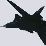
1/32 Mig-25_Foxbat PD
Serkan Sen and 18 others reacted to Bekim for a topic
here is the printed Cockpit with the Tempmodels ejection Seat .. and from the another side.... All the Best Bekim19 points -
Apologies for delay - but a little more progress. Base Interior Grey/Green - in this case MRP. Detail painting and weathering to follow - but the base coat shows up the superb detail... Dry assembled: With a tiny bit of trimming in places, the fit to the fuselage halves is superb! Main panel back and boxes sprayed black - and dry fitted: And the two halves closed up - again - just a dry fit at this stage. I've also softened the transition from the base of the canopy to the fuselage sides with a little Milliput - need to add some detail back. Absolutely loving this kit - the detail and fit of parts is fantastic - and hugely rewarding to work with. Iain19 points
-

Hasegawa 1/32 Ki-84 Hayate
Troy Molitor and 18 others reacted to Thunnus for a topic
After looking at the wheel wells under primer, I thought I'd add one last pair of hydraulic lines. These are copper wire with little sections of brass tubing. I also added a couple of circular covers punched from thin sheet styrene. After another coat of primer, I think the wheel wells are done. I usually paint the wheel wells now and then mask them off during the camo painting stage. But I think it will be easier to paint them after the camo painting so I'll skip that for now.19 points