Leaderboard
Popular Content
Showing content with the highest reputation on 01/25/2021 in all areas
-

1/32 Revell Me 262B-1/U1 Nachtjager
Pastor John and 14 others reacted to Thunnus for a topic
Thanks for checking in guys! Compared to the prior steps, especially the sculpting required around the nose, the painting portion just flew by, didn't it? The flat coat has been applied to the Nachtjager. I've been using Model Master Acryl Flat after trying many different clear flat products. It's not perfect but a dependable flat coat can be difficult to find. You may notice the very light post-shading that was performed. A VERY thin mix of black/brown is sprayed along joints and panel lines. I like this to be BARELY noticeable. The bottom was given a flat coat too. Post-shading was done using a light tan color and instead of running along panel lines, I used it to create random streaks, front to back. I decided to install the landing gear at this point. The last bits of hydraulic lines in the wells have finally been connected. I'm going to let the landing gear cure overnight. I want them solid before attaching the wheels.15 points -

Test Build: 1:32 Flying Start Models Tornado F Mk.3 Conversion (Revell base)
Paul in Napier and 12 others reacted to Iain for a topic
Thanks Piero - I think Tim's done an excellent job with the shapes! Spent about half an hour last night sanding joints - and this is the result (quick photos taken on mobile): And, well, I couldn't resist (rear hinge area needs a little trim) Iain13 points -

Ex-Czech Polish MiG-29A Fulcrum - Trumpeter 1/32
Paul in Napier and 7 others reacted to Piero for a topic
Hello, last we i worked on the front wheel bay. The plastic parts are ok but can be detailed and so I did it adding some reinforcement plates, hydraulic tubes and valves. Dry fitting the wheel bay inside the lower fuselage part is ok. Now its time to work on the central undercarriage bays... CIAO! Piero8 points -
MODEL KIT PREVIEW 2021 + New molds 1:32 NATO Pilots, Ground Crew and accessories are listed there: https://issuu.com/italeri/docs/previw_italeri_2021/8 Juraj7 points
-
I would go with Max on this one go with what you think looks right, below is a quote from Edgar. Posted 18 December 2014 - 05:07 AM This subject causes almost as much controversy as rivets. At the beginning of the war, aircraft camouflage colours were "blended," i.e. merged, but it was found that this was often done by lifting the gun away from the surface, so that paint was drying before it hit the surface, causing excess drag. At a meeting, early in 1940, Farnborough, who were the Air Ministry's source for camouflage, said that blending was a waste of time, so the Ministry sent a circular to all Resident Technical Officers, saying that mats could, in future, be used. This covered the manufacturers, and POSSIBLY the Civilian Repair Organisation, but probably not M.U.s., and certainly not the Squadrons. Mats probably caused ridges between colours, which needed smoothing down, but nothing like the roughness of the blending process, and a smooth finish was what the Ministry really wanted, but couldn't achieve with cellulose. Synthetic paint, in August 1942, was found to be smooth and matt, so was used until after the end of the war. Understandably, modellers often think of their model first, and the real thing second, and this is where the fun starts. Ideally, blended colours had a "join" only one inch (even half an inch) wide, which, in photographs, looks very prominent, but, divide that down by 72 for a model, and it comes to 1/3rd of a mm, or 1/2 a mm in 1/48, 3/4 of a mm in 1/32, even 1/24 is only 1mm, and spraying to those limits is really difficult (I've never managed it.) Ideally, taking all this into consideration, a model's finish should probably be hard-edged, but, as always, it's up to the individual, and long may that remain so.7 points
-

1:200 USS Missouri Build Log - Trumpeter w/ Pontos Detail Sets
ivanmoe and 6 others reacted to steinerman for a topic
Howdy Friends! Hope you are all safe and staying healthy. This is not a good time and I hope and pray that once more people are able to get the vaccine that things will once again start to return to normal. Being an old fart (78) I, along with my wife, have already gotten our 1st shot and are scheduled for our 2nd one in 3 weeks. But, I didn't post here to tell you about that! I have actually been working (now and then) on my ship, and, since I haven't posted anything since October, I thought I'd give you an update on what I've been up to. It's coming along - slow but sure, and I think I'm actually starting to see the end. During the last few months I've been working on the stacks, masts, and the main control tower. As you can see in the accompanying photos, I've finished these and am now working on the two seaplanes that are mounted on the stern catapults. After that, what remains is to build the small whaleboats and their mountings, add the railing along the sides of the main deck, and the rigging. Plus, of course the 300 sailors that will populate the finished model. OK, let's see some photos: Here is the front stack and the control tower in process. Lots of detail still to add yet but you can get an idea of why this part took so long to build. If you look close just below the wing of the top radar and again a little below the horn, you will see a box with three vertical lights, red above green above white. These are called "Fighting Lights" and depending on what pattern is lit tells the other ships in formation what the ship is doing. They are not lit during battle at night as they make excellent targets to aim at in the dark! Here's another shot from another angle. There is a ton of brass photo-etch on this sub-assembly - along with a lot of little fiddly parts! Here the foremast and the fore yardarm have been added. Also, more of the antennae that sticks out all over the bloody ship! More of the front stack assembly. The various brass parts are extremely thin and fragile. You can see the very top antenna is bent. It's since been straightened. There are 2 horns on the ship. One is a siren. Note the brass bell and the fire hose and red water supply valve. Yeah, I know - there's a bent antenna on this end of the yardarm. Every time I touch this I upset something! Here's a closer view of the yardarm and the SK-2 Air Search radar dish. This dish was a real ***** to make. It's not perfect, but from a few feet away it looks fine! A view from the top looking down at the MK-37 Gun Directors and the dual 36" searchlights. Note the detail at the top of the stack. This is all brass PE. The 12" searchlights mounted on the railings were a real bear to glue in place. And yes, the railing needs to be straightened. There's a lot of tweaking and straightening to do once this assembly is glued inn place! Here's the rear funnel and the attached mast and yardarm. While the mast on the forward funnel is taller, this one is called the "Main Mast". This stack has two 36" searchlights mounted on it as well as two MK51 gun directors on either side. Close up of the main mast and yardarm This is what the ship looks like with both stacks glued in place. The superstructure is just sitting on the main deck because I haven't screwed down the boat to the base yet. Looks kinda busy, don't you think? Antennae all over the place! A shot of the superstructure from the starboard bow. I don't know about you, but I think it's turning out fairly well. KInda hard to see the individual boo-boos when you stand back and look at the whole thing. You wouldn't think it, but there is a LOT of rigging to add to this ship. I haven't decided yet if I want to use EZ-Line or stretched sprue - or possibly a combination of both. This spot is where the Japanese surrendered on September 1945. I have a small table, chairs, and microphone, along with a whole bunch of Japanese officials and sailors. I don't know if you paid attention or not, but several of the windows on the bridge have windscreen wipers added. Wanna know how difficult that was - tiny wipers glued to tiny arms! The rectangular shaped structure on the deck with the sloped top is called the "Flag Locker". There's one on either side and all the signal flag halyards run down to these lockers. Notice a 3rd set of Fighting Lights on the outboard side of the 40mm Bofors gun tub. There's a flag locker immediately aft of the rear shack as well. This is for the battle flags, pennants, and Old Glory. You can't see it, but each of the 20 40mm Quad Bofors gun positions have tiny numbers on the sides of the tubs as well as on the sides of the shields themselves. (Trying to be authentic here, folks!!) OK, that's it for now friends! Stay safe and stay healthy!!!7 points -

1/32 HK Models Lancaster B Mk.I Nose Art Kit RF128/ QB-V Victorious Virgin.
Uncarina and 6 others reacted to monthebiff for a topic
Working through the port side and added the ground position indicator and switch box along with some cabling in the navigators position. With a bit of luck the interior will be finished this week and ready for some paint! Regards. Andy7 points -

HH-60G Pavehawk Kitty Hawk 1/35 DONE!!
Harold and 5 others reacted to Pete Fleischmann for a topic
Rescue hoist cable coming along- cheers Pete6 points -
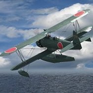
The modeling room has been renovated, oodles of space and light. Refreshing Thee F-84G has been once again set aside (don’t ask), the He-162 just needs a few more decals. Time for a new project. Oh look, another one! I will build both in tandem. I have built one before (below) so I know what I am getting. Great little kit. The Ki-86 looks so badass in this cammo. It was most probably the advert to Anime for Japan, who else would make a cammo scheme out of a bright orange scheme? The German one will also be finished per box art, and will look nice alongside the Arado Ar-196B in a similar scheme. Here’s my first:5 points
-

Bf 109G-10/R3, W.Nr.130297 10./JG 51
109 and 4 others reacted to Miloslav1956 for a topic
Hasegawa 1/32 model Eagle cals, Aires wheels, exhaust & cockpit, AMUR propeller & scoop, painting mask homemade, all colours MRP. reference:https://www.forcedlandingcollection.se/LWe/LW136-Bf109.html5 points -
I first started this in 2015-2016. I am now retired but work then was very draining and stressful( general surgeon working as a surgicalist in a hospital) So the ac got put away. It did not help that the fluorescent light in my diy spray booth fell off and knocked one of the engine nacelles off ocuh. I retired in 2017 but lost the drive to build along with many other life events(grandpa) I still participated here and meant to get back to it eventually. I took up the mantel and got back on the horse and finished it up. Thanks to Thunnus for inspiration David Brown for info on this particular ac and Michael swinburn for sourcing the D/L antenna which took a flight into the wild blue. Yellow 3 was an early build so it had the early scissor links on the nose wheel and you had to delete the pouches on the access doors of the cannons. It is also well worn the only picture of it is nose down in a dump after the war but you can see how worn the paint was. It was an interesting process to create the worn look. I did a partial wip on it but did not include the earlier paint work. It basically had a speckled irregular under coat thin main coat weathered with pastels and watercolors . The mask allowed me to weather the markings as well. Other than decals , masks, nano mold seatbelts(great thing they are) and barracuda wheels the ac is stock trumpeter. This ac aIso had the original wooden rudder and square tail light that was made by cutting off he part of tail and blending in a piece of clear plastic with uv glue. I love AM but it does complicate and slow and already slow process for me. One error was the wing walk silvered old decals and despite a glossy base under it. they are hard to cut as vinyl stencils on my cameo I think that hgw makes some wet dry decal or next time may use the dry transfers for that. The vehicles are a 21 century die cast the kettenkrad is a ZM I just built posted ready for inspection today5 points
-
more dangally bits, dont seem to do much with a whole days work and my daily tonka shot5 points
-

Which Tiger Moth kit? Part 11
Landrotten Highlander and 4 others reacted to mozart for a topic
Part 3 - THE COCKPIT Inside the cockpit of a Tiger Moth you soon realise that it's not a complicated affair: a joystick that waggles between your legs, rudder pedals, half a dozen instruments plus a compass, a throttle and one or two other levers that you may or may not need, and that's about it! But our three Tiger Moth kit producers have treated this area is different ways. Firstly a few views of the real thing, a fully restored Moth in some pictures, one being restored in others which helps to show structure etc. One or two bits of modern gadgetry have been fitted, most noticeably a radio/intercom box, but essentially these are WW2 standard. So what's in the kit boxes? It varies quite a lot in content and standard: You can see that the 1978 Revell-based kit is pretty simple.....and wrong! The front seat should be very different from the rear one, both Silver Wings and ICM have this right but ICM's looks a bit tight to me. Compare Silver Wings front seat with ICM’s then look at the last picture of the Moth under restoration, Silver Wings looks right to my eyes. The Revell instrument panel is also a disappointment, and sadly 50 years on ICM seem to have taken little more effort to make something more presentable.....half a compass moulded into the IP doesn't do it for me and means surgery and scratch-building almost immediately with either kit. On the Revell kit the bulkheads behind the pilots' heads don't include the horizontal slots......but that is where the seat belts are attached. The Silver Wings kit is by far the most detailed, the most complicated, the most challenging and the most fragile! Even cutting out the resin flash can spell disaster with the merest slip of a knife. A build up of tolerances can also lead to a very tight fit into the fuselage. Some shots of work in progress on the Silver Wings kit. The "!" is the resin control horn in position, I thought it would probably snap off ...... and it did so I replaced the whole thing with a scratch-built brass piece. You can see though how fine the castings are. The ICM cockpit is a compromise between the two, probably enough detail with the exception of the IP, without being too complicated. Leaving the front and rear side doors open will show a lot of the cockpit so there's a lot of potential and reason to spend time getting the cockpit right. Extracts for the cockpit build-up from the instructions give an idea of what each demands in modelling input. Firstly Revell.....stages 3, 5 (at a push), 6 and 7....that's it.....simple! and it fits in here: You'll notice the Silver Wings internal fuselage just has location points, here are their instructions: and the ICM fuselage has some good looking frames moulded in place, their instructions: I think like the idea of putting the main control box and seats onto the wing and thence into the fuselage at a later stage, though if you want to add the control lines for the throttles for instance it doesn't work so well because those lines run through the whole cockpit, front to back. Wartime Tiger Moths were fitted with simple four-point Sutton seat belts, Silver Wings is the only kit to provide these in photo-etch form: That I think just about ties up the cockpit area, I guess you pays your money and takes your choice as to how detailed you want it to look, I think most modellers will spend a lot of time here. Part 4 looks at wings and things.5 points -
Memory does serve. Columbine II was flown from AZ to VA in 2016 (after a pretty serious airworthyness refit) to undergo complete restoration. It's very nice to see people keeping these old machines flyable. Here's a spectacular shot from the flight east: Unfortunately this isn't the exact plane I'm doing (Columbine III), but great to see nonetheless.5 points
-
JU87B-2 Colours for North Africa
MikeMaben and 4 others reacted to monthebiff for a topic
I used Tamiya Desert Yellow if I remember correctly on my 32nd scale Trumpeter build. Regards. Andy5 points -

41sqn Tornado - One Giant leap!
HerculesPA_2 and 4 others reacted to Mark M for a topic
so the tanks and Paveways are done, right whats next...5 points -

Make the others jealous
Michael931080 and 4 others reacted to Gazzas for a topic
Thanks to Damian... My Synthetic Ordinance Works landing gear arrived today... and do they look sharp!5 points -
Priller Double Thriller Part 2 - Trumpeter Bf 109 E3 1940 Complete
mpk and 4 others reacted to Panzerwomble for a topic
Pics Now one piece, filled , primered with light blue , done the yellow . Top tip from my bike spraying days , when spraying bright colours, reds, oranges, yellow etc, undercoat with white for a bright colour , spray over grey and it'll dull it right down .5 points -
Cockpit plus engine bay are now essentially complete. Started work on the empennage and the various filler pieces that complete the fuselage. There are separate sections that drop in for the section in front of the vertical tail (so you can do different drillings for the different possible antenna combos) and for the section of fuselage that contains the rear LG. The latter is notionally to allow you to switch back and forth between gear down and gear up, but it's convenient in that it allows you to build and paint the rear gear completely but not install it until the fuselage is fully painted. With any other kit brand, there would be issues around these parts not fitting perfectly and just adding sanding/filling/fitting chores. With Tamiya, they just fit in perfectly and seamlessly. Anyway - here are some up to date photos of the engine etc.5 points
-
Just arrived yesterday (Goodwill auction from a couple of weeks back), and cheap it was too. I was so delighted, that I built almost the entire thing last night, just like a little kid. I love it.5 points
-
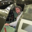
Having spent a fairly intensive 3 weeks on my GB P-51D, I decided that I needed a short break from scratchbuilding tiny details. So I'm going to give in to the airliner frenzy that Kev's started and do a quick OOB project. The C-121C is the military version of the L1049 Super Constellation. On Kev's suggestion I located a copy of the Revell kit rather than doing the Minicraft one. This kit comes with two schemes - the general purpose military transport shown above and Dwight Eisenhower's personal Presidential transport, "Columbine", which I will be doing. Four sprues of weird silvery plastic, plus some clear parts.4 points
-
boxart and preorders open4 points
-

Battle of Britain Hurricane camouflage demarcation, hard or soft? 2 photos.
Sepp and 3 others reacted to Oldbaldguy for a topic
I vote for softly hard. Hardly soft works too.4 points -
This is a used kit, and the guy I bought it from let me know ahead of time that there was one broken part. Fortunately this broken prop is still attached to the sprue, so I was able to nudge the blade back into position and hit it with a drop of extra thin cement. I'll let it harden off for a couple days and then *carefully* cut it loose and hope... First order of business is to delete some windows. The kit was designed to build the civilian L1049, so it has all of the passenger windows. DDE's plane had a number of them blanked off. To fill them I cut sections of the clear plastic window strips that came with the kit, and CA glued them in. I then applied more CA over the outside to seal the edges and build up past the fuselage contour. It's not easy to see in the photo above, but about half of the windows need to be eliminated this way. I'm counting this as still "OOB" since the kit instructions tell you to do it ;-) A quick shot of accelerator and they sand down pretty easily. The windows that remain as windows I'll do with Krystal Klear at the end of the project. For that to work well the edges of the window openings need to be quite thin, to avoid a sunken appearance to the final window. So I need to do something about this: A quick hit with a rotary tool burr: And you get this: Which should work better. The kit supplies a rudimentary flight deck, which I'm not going to use (I'll paint the inside of the cockpit transparency black before gluing it in), so now I just need to add some lead weight and close the fuselage up.4 points
-
couple of things - i suggest getting this book if you want an excellent resource on early Hurricanes - if going for a feathered edge, depends on how tight you can spray - if considering scale, a feathered edge is unlikely to show up in 1/32 given limitations of one's ability to spray those tight lines - feathered lines may still be aesthetically pleasing, even if not entirely accurate (I certainly find them so) but definitely get the WingLeader Photo Archive book!4 points
-

Tamiya (not a speculation thread)
Granger Davis and 3 others reacted to LSP_K2 for a topic
Shoot me an address, and I'll get you some anti-depressants.4 points -
Some more progress...this time with a little paint on the parts. I've got some touch-up and detail painting to do with the torsion bars. Then comes the washes and drybrushing. The primer red-brown is by AMMO and the torsion bars themselves are painted Tamiya XF-18 semi-gloss black. The pipe joints are 3M electrical tape, with aluminum duct tape (the actual metal duct tape, not the fabric stuff) with 0.020-inch adjustment screws. These last little parts were a huge PITA as I used tacky glue and too often they stuck to the damn tweezers and would NOT stay on the band... eventually, I got them all on. I think I may add a little superglue over them just to make sure they stay in place. Lastly I'll add the weld beads to the cross-beams where they attach to the hull sides...that's for another time though.4 points
-
JU87B-2 Colours for North Africa
Sir Spendalot and 3 others reacted to D.B. Andrus for a topic
The initial 1941 shade of "79" was very light and yellow, especially with 109E's. The later versions of "79" were more in line with what we tend to see on models today. There is a swatch of this yellow hue in Merricks last volumes of Luftwaffe Camouflage and Markings. Also, keep in mind how the underlying paintwork would influence the new topcoat, especially that of a lighter shade. HTH, Damian4 points -
Revell 1/32 Heinkel He 162
Alain Gadbois and 3 others reacted to Grunticus for a topic
In the last few days I have redesigned my modeling room completely. New bench, lighting, layout. Lots more space and light now. The drawers are not installed yet. As we all know no one can finish a half ready kit on a brand new bench (the F-84G, which gave me more grief and was set aside once again). So I’ll start a dual-build of two Bu-131’s soon. Today I did feel like finishing the He-162 first. Notice how I divided the stash left and right so it seems like a normal quantity The new setup: Base markings and Werksnummer have been airbrushed using masks cut with the Silhouette cutter. The rest will be decals from the kit. Sorry for the not so good focus, the new LED light gives my IPhone an issue with flickering shutter. More soon.4 points -
Test Build: 1:32 Flying Start Models Tornado F Mk.3 Conversion (Revell base)
Coneheadff and 3 others reacted to Iain for a topic
Whilst I'm here, the intake trunking has been taken out of the airing cupboard for a coat of looking at, and a bit of sanding. Looks crude after three dips (it's household emulsion paint, so it will be) - but sands easily and should give some nice smooth trunking: Sprue handle is a press fit into a previously drilled hole - stops me getting too messy whilst I dip the part. And the important bit - a little sanding to be done later: Making good progress now - may have a full airframe by next weekend! Stay safe! Iain4 points -
Now this would be a nice kit for Hasegawa to release in 1/32 given their overall approach to tooling. They do have 1/48 versions they could reference and update as needed to correct any glaring errors that may be baked into the 1/48 kits (I’ve never heard of any but I haven’t been looking). While the MDC kit is grand, I and others like me, just aren’t keen on building resin kits.4 points
-
OK - some pix. Bear in mind this has involved some major modifications so I'm very pleased with how well everything lines up! Assembly done with Revell Contacta (the one with the needle applicator) for maximum strength, and minimal shrinkage. Aires cockit tub bonded with thin superglue... I've just spent 5 mins with some sanding sticks and everything mostly blended together beautifully! Now, that emergency canopy release - here's a photo of the real thing - printed out and bonded behind the clear cover. Looks OK I think - remember, this is only about 4.5mm diameter... And some initial assembly of undercarriage assembly halves, and under-nose intake. Note that the oleo section on the nose leg has been separated - this will be shortened later to improve the 'sit' of the final model: Back later, perhaps... Blue skies! Iain4 points
-

Italeri CF-104 Starfighter "Kicked up a Notch": KLP Publishing eBook now Available!
KiwiZac and 3 others reacted to chuck540z3 for a topic
Thank you Gents! January 23/21 A short update, but I think a very important one. The fuselage has been glued together and all gaps have been filled with CA glue and sanded smooth. This was tricky on the dorsal area, where there are 10 small square access panels that need to be rescribed after filling. Thankfully they line up pretty good, but that’s partly because the panel lines are so darn big! The Eduard exterior set has these little panels in brass to cover them, but since they are so small and curved, I left them off since I think they will cause more headaches than they solve. On the underside, I left off part C-9, so that I can install the main landing gear at the end of the build. Here it is dry fit to the rest of the fuselage, which is a bit of a mess just forward of it on the left. This must be a well-known problem, because Eduard also has a brass plate to cover this area, so I glued it in place and then sanded it to remove any sharp edges and help the paint stick to it a bit better. I also decided that since I will have an MN-1A bomb dispenser (modified SUU-21 dispenser) hanging from this part, I should have some extra strength here that is easy to glue to underneath, so I installed styrene strips that conform to the curvature of the part. Part C-9 will not only be an easy drop in, but strong as well, although the arrow head should not have a panel line through it. According to my Wingman Jari (Finn), that recess forward (left) of the brass plate should be filled. Consider it done. Thankfully the center line pylon that the bomb dispenser hangs from will cover this, so you won’t be able to see it easily. Moving forward from the center, I had a very hard time installing the front landing gear assembly, because it wouldn’t fit flush. At first, I thought it was interfering with some of the resin assemblies I installed above it, so I spent a very long-time trimming pieces and dry fitting, but to no avail. Finally, I shone a flash light from the back through the part C-9 opening and discovered the culprit! The port/left side of the gear bay was rubbing up against the gun compartment, which has nothing to do with all the resin I installed. After sanding the outside of the gear bay and the gun compartment, everything slid into place nicely, so here’s a tip for you who may have the same problem in the future. In all my frustration with this assembly, I forgot to install the clear light F-5 from behind in that little hole on the left. Dang! Now I’ll have to install one from the outside the hard way. Recall that I had a lot of gaps to fill and detail to add in the front cockpit area. All better now, but a lot of picky work to fill the gaps, and add a styrene strip behind the cockpit missing on the kit parts, without wrecking the delicate detail of the avionics bay. This time I didn't forget to install the little light at the top of the fuel cover! I also created a new avionics bay cover hinge out of modified styrene I-Beam, instead of the brass one I had before. While the brass hinge would have worked, the styrene one is much more flexible and easier to work with, and allowed me to scribe hinge markings on it which you can’t really see very well in this pic. Here is the hinge from the rear, unpainted so that it will stick to the cover. I sanded a slight groove in the sill for it to sit in, so that it will be an easy drop in at the end of the build. Here is the hinge glued to the cover and dry fit with tape, which shows the hinge detail a bit better. From reference pics this door opens about 80 degrees, while the canopy is closer to 90 degrees, so I can adjust the angle accordingly when I glue it in with Gator glue, that is flexible and easy to clean up with water. When installed permanently, I will add additional wires that go from the cover to the bay itself. I end this post with a problem to fix. The windscreen is too wide for the fuselage and based upon a quick review of other builds, I’m not alone. After painting it underneath, I installed it a tiny bit rearward to help with the width, since the further you go back, the wider the cockpit sill. I also squeezed it slightly, being careful not to overdo it and risk cracking it. I plan on sanding the edge of the windscreen to narrow it, rather than just add filler that will look wrong. This in turn will erode the fine fastener detail on the bottom, so I plan on redrilling some of these recesses to recover what I sand off. For the CF-104, the front infrared sensor at the front of the windscreen was removed, which was another pain because it's hollow and needed to be filled. When I finish that, I will add the brass side rails to cockpit sill that will eliminate the square opening in the corners. I hate it when clear plastic parts have challenges, because the plastic is so brittle and hard to work with, but I’ve been to this movie before and maybe I will have a happy ending once again? I also crashed and burned with my Kitty Hawk Harvard build that gave me fits with the canopy, so wish me luck! Cheers, Chuck4 points -
HH-60G Pavehawk Kitty Hawk 1/35 DONE!!
Harold and 3 others reacted to Pete Fleischmann for a topic
I invented a few new bad words getting the gunner set properly..but he’s in! cheers Pete4 points -

F-4E Kurnass 2000 1/32 Tamiya
Loach Driver and 2 others reacted to Peter Gregor for a topic
Hi, so another Israeli bird is out. It is an F-4E Kurnass 2000 number 650 from the Bat SQN, Tayeset 119. The F-4E kit from Tamiya is used as a basis. The building was quite comfortable, I did not encounter any major problems. I used the cockpit from Avionix, of course, supplemented with a modification of the Kurnass 2000 version, MFDs, few switches, and a new HUD were added. I also used the seamless intakes from RealModel and thanks to Miro Medzihradsky for the dimensionally accurate engine nozzles. The refueling probe and part of the decals from Isracast are complemented by Hebrew stencils from Skys Decals. The armor plates in the lower part are cut out with a plotter, the central fuel tank is from the F-4J kit modified to the IAF standard. What bothered me the most was the slatted wing, but I think that the result revived the model. The AGM-142 with a pod are from the F-16I kit, but it was necessary to enlarge the pylons because they were specially adapted for these missiles and I also redesigned the guidance part of the missiles. The outer pylon for AN/ASW-55 is from RealModel. The AN/ALQ-184 (short) ECM s from AMS Resin and the adapter for ECM and reduction for the Sidewinder to the AIM-7 shaft are homemade. The whole model is rescribed and riveting according to available materials. The wheels and arresting hook are produced by Eduard. MRP colors and Ammo Of Mig washes were used on the surface. The sources are from Isracast and Double Ugly Books. Thanks for all comments. Added pictures:3 points -

1:32 scale Ansaldo A.1 'Balilla'
Harrison90 and 2 others reacted to sandbagger for a topic
Hi all, The tail unit is rigged now. Twin bracing wires, rudder control line and elevator hinges. Also added the 'metal' retaining strap at the rear of the fuselage at the tail plane leading edge, Mike3 points -

Who’s into R/C things?
Rick Griewski and 2 others reacted to D Bellis for a topic
Yep. Thanks to my dad who was already an accomplished R/C pilot, I started flying R/C in the early '70s. I built my first trainer (RCM Basic Trainer with an OS .15FP) and HeathKit radio at age 8, 'soloed' it before my 9th birthday in October of '74. I never really stopped flying R/C since then, but I have taken breaks for things like serving in the Army, etc. The biggest in my stable is a 102" P-51D from Bud Nosen Models, and the smallest is a 13" Fokker D.VII converted from an FF 'stick & tissue' kit. After converting to all electric about 10 years ago, I settled on hand-launch airplanes in the 30" - 40" range. My standing favorites are FMS, Alfa and Flying Styro WWII airplanes, of which I have dozens. I'm also a big fan of the ParkZone airplanes. It's just a shame that they went under after losing track of their Park Flyer roots. Some pics of my older stuff are posted HERE. D3 points -
Next version............. RAF F3 ???? Hope they're working on that one too!! Now that would break the piggy bank open!!!!!3 points
-
Nice choice Alex (I always blame Kev...it's normally his fault anyhow! lol ); I look forward to watching your progress. I will probably join this madness later this year with my old Revell 1/115 scale P-3C Orion kit once my long-term commitments are out of the way. Cheers Derek3 points
-

JU87B-2 Colours for North Africa
Sir Spendalot and 2 others reacted to Royboy for a topic
I've studied quite a few photos of aircraft from that theatre and some paint jobs look relatively pristine and some look quite 'shop worn' at times. I think you have to make a judgement call on the level of operational wear on the airframe when you do a model like this. Obvious things like sand/weather erosion, fuel and hydraulic oil stains and some elements of sun bleaching over time can have quite a visual effect. It's quite a conundrum but does give the artistic element a chance to shine on battle weary machines. I normally go with a picture of the subject if I can get one to give me some idea. Anyway, your model looks great, enjoy it and go with what you like!3 points -

Tamiya (not a speculation thread)
LSP_K2 and 2 others reacted to BloorwestSiR for a topic
Well, it's a 1/48 F-4B. Scroll down to see it. https://www.tamiya.com/japan/featuredreleases_early2021.html3 points -

JU87B-2 Colours for North Africa
Sir Spendalot and 2 others reacted to RBrown for a topic
As Damian states the early version of RLM 79 was very light and yellow. In the photo below the upper surfaces are 79 but the lower cowls are yellow...3 points -
I built this kit about5 years ago and absolutely loved it! I'm a fan of the less popular, ugly and supposed underdog aircraft, so for me this was a must have. I will admit, being new with my Grex airbrush at the time, I settled for a more simplistic paint scheme. Now that PCM has closed up, I hope someone else picks up the Italian aircraft as they are sadly under represented and quite unique.3 points
-
Seat, main fuel tank, auxiliary fuel tank, not sure how much of the fuel tanks will actually be seen. Waiting for some Evergreen plastic to make cross members to mount the fuel tanks. I'll use lead foil to make the straps that hold the fuel tanks in place and plastic tube for the filler spouts. The brass of the seat is from the Tom's Model Works British PE. I made a seat bottom out of plastic sheet, didn't want to use the brass piece from the PE. The blue is wire insulation.3 points
-

HK B-17...C 5/4 sweating the metal
Starfighter and 2 others reacted to brahman104 for a topic
Thanks Terry! I'd put off doing the tail wheel for a long time as I wasn't really sure how to do it, but eventually it came together Agreed, there's lot of little sub projects going here, the question is: Will this year be the year we see them all come together? I sure hope so! That's certainly the plan Matt, she's putting on weight at a rapid pace these days! Thanks Tom! I really love working with brass, and parts can be as simple or as complex as you choose to make them. Give it a go, you won't regret it! It certainly is Mark! Another small update, but one I'm happy to have done. My order of scale hardware arrived from the States, so I disassembled the gear in preparation for painting. Nothing fancy here, just primed and painted aluminium, with a little bare metal foil for the strut and some DDG to break up the colour on one of the links. My retract screw looks much better with a wash. I also found a resin electric motor from a verlinden workshop set so that became my retract motor, with a little more creative painting and some wiring, it should look the part! Here's how it looks so far: I've also been working away at the shroud that sits partially around the tail wheel. A couple of years ago Tim (Wunwinglow) sent me an assortment of resin-machinable blocks. I always thought I'd find a use for them one day and today was it. Taking the fuselage contours from the tail wheel cutout in the fuselage, I cut, sanded and filed a male profile to form some litho plate over. In hindsight, I should have just used this to vacuum form the piece over, but I'd been reading Gerald Wingrove's "The Complete Car Modeller" over Christmas and wanted to have a go at forming a complex shape in metal. Firstly, here's the "buck" I then took two roughed out pieces of annealed litho and, working one side at a time, firstly creating folds with pliers, then working out those kinks with the hammer, started to coax the metal to my will.... After a few hours, I had something that looked pretty close. Still needs work, but you get the basic idea! At least the #8 bulkhead is back in place. Time to make that toilet I think! Cheers, Craig3 points -

NEWS IN HpH !!!
scvrobeson and 2 others reacted to Mirek O for a topic
New model in 1:48 (but large :-) ) http://www.hphmodels.cz/hph/dornier-do-x-148/?lang=en3 points -
Stage 'The Next' - missile fin cut-outs. I had an idea - strange, but true... The layout/spacings for the holes mirror those in the front insert so, I thought, put that on the scanner, scan, then mirror. Print out on paper, trim to size and we'd have a template. Simples! This is the mating surface of the front fuselage insert/3D print: And the scanned/mirrored/printed template. Positioning is straightforward - align centre - then rear edge of second slot from rear lines up with panel line - see arrow. I've scribed through with a sharp blade, so next I'll cut out the slots. Iain3 points
-
F7F-3 Tigercat - BuNo 80405 - VMF 312 MCAS - El Toro, CA 1946
R Palimaka and 2 others reacted to Out2gtcha for a topic
MLG bays are done, the nacelles are fully and permanently attached, and the firewalls are fared in to the top of the wings: While not perfect, the fit of the nacelles to the wings was pretty decent, and will only requite a minimum of filler or corrections: The tops of the nacelles was very carefully aligned with the panel lines on the tops of the wings, and thick CA was applied to fill any major gaps. No need for anything fancy here on top in this section, as you will see why later in this post: I ended up taking a series of finer mesh sanding sticks to the top nacelle area as to get the transition as smooth and step-less as possible: Taking a very small page out of Peters book, I used the tape flap method to apply some contact adhesive for the upper PE wing/nacelle pieces. These large PE parts have raised rivets where required and will negate any need to fill or re-detail the area where the wing meets the nacelles: I dont have any pics of the finish product yet, as by the time I used some balsa wood blocks to smooth things down, then applied thin CA to any edges that needed it, it was pretty late. The landing gear SHOULD be next, but I ran out of the correct size of stainless steel tube I need for the front oleo strut, so I placed an order for some more tubing. I will have to move onto other things in the mean time, so my plan now that I have the large upper wing PE parts in place, is to do some smoothing and finish sanding on the whole exterior, as I havnt really touched that in years. I need to apply an overall primer coat of white to see where I am at in regards to what I need to sand in order to apply the rest of the smaller PE parts. Cheers!3 points -
Well, the short answer is.... it depends on who built the A6M5. For Mitsubishi built A6M5's: a. undercarriage bays and covers - lower surface color. b. flap interior - aotake c. engine cowl interior - blue-black For Nakajima built A6M5's: a. undercarriage bays and covers - aotake b. flap interior - aotake c. engine cowl interior - semi-gloss black Undercarriage legs are black with stainless steel/chrome oleos. As far as I'm aware, there is no "early,mid or late" war interior green for the A6M Type 0 fighter. The only differences I'm aware of are the interior green used by Mitsubishi and the interior green used by Nakajima. Model paint manufacturer's refer to this as "Nakajima Interior Green" and "Mitsubishi Interior Green". Neither identification is entirely correct but is sufficient to draw distinction between the two. They are two distinct shades of green, the lighter of the two being Nakajima. Mitsubishi's interior green color is close to FS34102 but a little darker. Definitely NOT US interior green (FS34151). I bet your next question will be: How can I tell who build the aircraft I'm intending to model? Well that's a lot easier to determine than you might think. All you need do is look at the demarcation line between the upper and lower colors on the fuselage. If the demarcation line sweeps from the trailing edge of the wing to the leading edge of the horizontal stabilizer, it's indicative of an A6M5 built by Nakajima. Mitsubishi built A6M5's have a constant demarcation line flowing in a straight line back from the trailing edge of the wing, underneath the stabilizers to the tail. The above link posted by vince14 is applicable in this case but primarily deals with the early series of A6M, the A6M2. The A6M5 differs in many respects in coloration of various components. NOTE: Aotake can be any number of shades between translucent blue and green and is usually somewhere in the middle (blue-green). The word aotake in Japanese means young bamboo (Mikesh, Japanese Aircraft Interiors 1940-1945, Monogram publishers, 2000). It is not uncommon to find different shades of aotake on various parts of the aircraft. Ryan Toews is also a member here and has extensive knowledge of the A6M series of fighters. I think his userID is A6M. I'm sure if you PM him, he can authoritatively answer all your questions. If what he says contradicts what I've written above, please use his guidance as he's much more knowledgeable than I am.3 points
-
1:200 USS Missouri Build Log - Trumpeter w/ Pontos Detail Sets
Scotsman and 2 others reacted to steinerman for a topic
Hi all you LSP friends out there. It's a wet, cold, gloomy day and since I can't be outside picking up leaves, I thought now would be a good time to give you an update on my "Plastic Toy Boat", or, as I call it - "The Monster Mo". I would say it's probably 75% finished ay this point. I have to put on the smoke stack assemblies and the front upper control bridge yet, then add the rigging (ugh) and add a bunch of little piddly stuff on the main deck. And oh yeah, I've got to do the airplanes that attaches to the catapults. And don't forget the people! I take that back, maybe it isn't 75% done!! Anyway, here's the latest 35 pictures. It's actually starting to look like a battleship now. Still a ways to go, though. Finally got the 2 20mm AA guns mounted on the bow. Railing on main deck won't be added for a while yet. This is the area I've been working on for well over a year now. The higher up you go, the smaller the pieces are, and the more brass photo-etch there is. There are 2 masts on this ship. one mounted on each of the twin stacks. The masts are 100% brass. Yeah, I said I was gonna! You probably didn't see them. but there are 11 windscreen wipers mounted on the bridge windows. And, I did get the railings installed on the upper decks - not the main deck yet. How's that for detail! I even have an open door under the gangway. Can you see the big 36" searchlight in what looks like an inverted tub? That searchlight has 16 individual pieces to it, including a clear plastic lens and seats for the operators One good thing, there is so much going on with this model that if I make a goof, I doubt seriously if you'll ever notice it! At least I can hope!! Sure is a lot of guns on this beast. Can you imagine a Japanese aviator's thoughts as he flew towards this ship trying to attack it? This is one area I had a lot of trouble with - trying to fit the two 5" practice loading machines in place along with the gun director and radar tubs and ladders, then adding the railings and net baskets. A bloody nightmare, it was! There's a 12" searchlight that had to be glued to the top rail of the railing. Wanna know how much fun that was? Damn thing is so small you can hardly see it and you have to hold it in place with tweezers until the glue sets up. Then you get to do it on the other side as well. Here you can see the hole where the aft smokestack goes. That's what I'm working on now. With the addition of the 12 whip antennas, I can no longer cover this ship with a piece of plastic. So, I now keep it downstairs in the family room and keep the case on it. Then, as I finish a module, I'll add it to the ship. Next addition will be the aft stack with it's associated mast.3 points