Leaderboard

Popular Content
Showing content with the highest reputation on 05/16/2019 in all areas
-
Factory Corsair Tamiya
Loach Driver and 15 others reacted to Gisbod for a topic
Hello all, Tamiya’s masterpiece Corsair. The best kit I’ve ever gotten my sticky mitts on. Grey Matter engine bay and various additions - see the build log for details. Thanks for looking in Guy16 points -
My fascination with Soviet Cold-War military hardware continues unabated. The Hind is arguably the most iconic helicopter gunship ever conceived. Sure, it has been technically surpassed by now, but not before striking fear into the hearts of all who tried to run or hide from its near alien presence! Given the pivotal role the Mi-24 played in Afghanistan, it is hardly surprising that at the same time it would end up in another supposed Cold-War proxy - Angola. It was flown by Russians, Cubans and Angolans (and possibly even East Germans) during some of the most intense modern combat seen on African soil. As in Afghanistan, the American "Stinger" would prove to be a deadly opponent, as well as the Soviet's own RPG, but a little known South African weapon would prove to be the most deadly of its opponents. I was inspired to build this after seeing Malcolm Reid (a fellow South African) do a beautiful job with the Trumpeter kit. http://www.saairforce.co.za/forum/viewtopic.php?f=21&t=8917&sid=7b9f0cc308e989bd28f8621829bbaeb9 Malcolm mentions a couple of interesting shortcomings in his build, and I will try to address them in my attempt at this great looking kit. The first is a question of two and a half degrees. It seems too little to bother with, but if you look at the Hind a lot, it becomes very noticeable. I mentioned in my MiG-29 build that Misha had done a sterling job in correcting this, but I am going to try a short-cut to get the "twist". In these pictures you can see how the "cockpit" is offset from the rest of the fuselage, and it is most noticeable by the apex of the canopies not being in line with the centre of the engine intakes. When on the ground, assuming the oleo's and tyres are equally inflated, the main fuselage lists to starboard when viewed from behind. I will concentrate on theses two points. The kit's cockpit and cabin are pretty well represented, but as with most Trumpy kits, just need that little bit extra. The Eduard PE set is used as a base, and then fleshed out with some extra styrene bits. Some vents added to the ceiling and a bit of structure and wiring on the aft bulkhead. The front seat was given a parachute made with leftover PE and lead foil that golfers use - handy stuff. The rear seat was left as a bucket seat, and some extras added to the controls at the back. The door frame was thickened and detail added. the same will be required inside the canopy frames as the Mi-24 has sturdy framing throughout. The troop seating was a little basic, and flat - a little extra styrene goes a long way to improving the look. Kit buckles from the PE fret. Drilling out some of the overstated detail and adding wire guards is all that is required for these consoles. The space between the cockpit and the cabin is devoid of detail, probably because it can't be seen, but I couldn't stop myself! I'm sure you can make out the rest without any further explanation... I suspect that this area may present some challenges when it comes to painting Cheers, Sean5 points
-
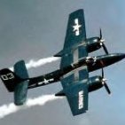
Went to my local monthly hobby night and on our display table was a Super Hornet. Long story short, it became mine for free! The kit is 95% done, with the builder sort of giving up because of an issue with one wing (a bit lopsided) and not finishing the ordnance, particularly the AIM-9X missiles which were missing from the kit. Took me about an hour, but I disassembled what I could, including the offending wing, but also all the undercarriage, canopy, seats, tails and nozzles. He didn't use very strong glue so it was relatively easy to manhandle apart. The only extras on the kit were resin seats - which are too tall to close the canopy - and some photoetch for the cockpit. Rest is stock. I'm clearing my bench to finish this, where my plan is to convert to wheels up, repaint and weather the heck out of it, providing a great testbed for my other naval aviation subjects. I shall call it the "Recycled Rhino" Here we go...5 points
-
After some oils5 points
-

Lt.Col. Maxwells BUSTER - FINISHED
Biggles87 and 4 others reacted to blackbetty for a topic
started with fitting Harolds corrected gun panel to the forward fuselage, careful cutting through the very thick plastic is in order5 points -

WNW Pfalz D.III Komplete 23/Mai/19
Durangokid and 4 others reacted to Gazzas for a topic
Now to an area that nobody seems to be talking about: The wing edges. (the following two images for discussion only) In researching I found two types: One on this Fokker D.VII where rib tapes are used: For this to be an option, your upper and lower rib tapes need to meet up perfectly both front and back. Then there is this Pfalz D.XII: Here, wing material in a strip more broad than the rib tapes is used. Since my rib tapes don't line up perfectly, and because I'm building a pfalz... I chose this method. I took this steep angle shot and discovered a step in my wraparound. I think it's gonna be there for posterity. The Lower wing. Ugh... macro shots show just how un-straight my rib tapes are. This small area hasn't been done yet. I took the picture to illustrate the fragility of the decals that don't wrap around the wing edge. Dirtied up the wheels with a couple of washes. Thanks for looking! Gaz5 points -
Yep, that I agree with, even as a hard core 32nd builder. There are just certain things that cant or because of size issues and the like shouldn't be built by the average modeler in 32nd................. Except a B-58 Hustler. That is way too big to be built in 32nd, and should never be attempted in the scale. Therefor a 1/32nd B-58 is at the TOP of my want list.4 points
-
As that well-known sage and philosopher Anon once said: "Do not be afraid of moving slowly. Be afraid only of standing still." And while progress on the RE.8 is slow, there has been some of late. Lots of details like adding the forward Vickers and its interrupter gear; windscreen; building the Scarff ring; painting the leather surrounds on the pilot's step and control cable exits; and other odds and ends. Today's plan: main interplane struts and rig the rudder, elevator and tailskid control cables. Thanks for looking.4 points
-
Hello fellow modelers. I now embark on my 4th and final 1/18 scale mod project - an F4U Corsair. My past efforts have been a P-51D (Miss Velma), a P-38J (Lucky Lady), and a P-47D (Glen Eagleston's Eagle). You can find articles on the P-51 and P-38, and WIP and RFI posts on the P-47 on this site, if interested. All three took more than two years each, and I expect the Corsair will too. At least. Here are the customary "before" shots: Cool huh? I obtained this toy/model a few years ago along with the P-38 at a local hobby shop where a whole bunch of these large toys were donated by an estate. As you all probably know, these things are no longer manufactured. The manufacturer is Blue Box (probably originally 21st Century Toys). The date on this one is 2005. To my eye at the time, it looked realistic enough to be a good mod project. My plan is to greatly improve the following items: Engine (all new scratch build, including back section) Engine compartment including engine mount Cockpit Landing gear Gear bays Wing fold mechanisms Flaps Ailerons Elevators Rudder And there will be smaller projects as well too numerous to list, similar to what I did with the other aircraft, except even more ambitious. I hope my eyes are not bigger than my stomach here - it is entirely possible I run out of steam somewhere along the way, or not get up to speed at all. After all, I just finished the P-47. But I think not. I'll take my time and try not to put any pressure on myself (yeah right!). So when I sat down and really inspected this toy, I saw things I like, and things I don't like. As usual there are lots and lots of inaccuracies that are fixable - I expect that. Here is what I did not expect - I was very disappointed to see that the engine cowling is not correctly shaped. I mean it is deal breaker to me unless I can fix it. Here is what I mean: The engine cowling has a round cross-section just like it should. But it should also have a slight taper as shown in this side profile (drawing VS-33001): Can you see it? The taper is slight but noticeable (at least to my eye). Now look at the toy model: From the cowl flaps forward, this cowling has a constant cross-section. No taper at all until you get to the front end. This sticks out like a sore thumb, makes the nose look bulbous. So what to do. Well, this model is going to get a complete engine anyway, with removable cowl panels. So the cowl flaps and panels over the engine will be replaced anyway. The nose cowl must be salvaged (I know not how to make one). The fuselage aft of the cowl flaps is just fine shape-wise. The typical gage of the plastic is .08 inch - robust. After some research it turns out that if the nose cowl could be decreased in diameter by about .08 inch (.04 inch on the radius), and reshaped to blend out the shape, I would still have about .04 inch gage to work with on the nose cowl, and I would get the slight taper I want. Some of you know I own a small desktop lathe (a Unimat). So I decided to try to turn the cowling on the lathe. To do this, I had to lop off the cowling: I was thinking at this point if this blows up in my face, I will just not do this project at all. Here is the cowling on the lathe chuck: Ha! My lathe is intended to work with raw material no larger than about 2 inch diameter. This cowling is a bit over 3 inches diameter! I had to put a large spacer under the head stock mount (see it - its that silver spacer). I had to mount the cowling very carefully - no wobble allowed. Then I rotated the head stock about 2 deg and proceeded to turn material off the nose: Then I removed the nose cowl: Success - that worked way better than I thought. So I am off to the races. I guess the engine is going to be first on the list. The Corsair was powered by the Pratt & Whitney R-2800 double wasp, as was the P-47 Thunderbolt. For the P-47, I dedicated about 6 months of my life scratch building a R-2800. And it didn't include the aft section. This time, I intend to make use of 3D printing in some way. At the very least, the cylinders will be 3D printed. So perhaps it will not take so long and not be as tedious. Hope you can look in from time to time! See ya!3 points
-

Any Tamiya 1/32 rumours?
CyberGolem and 2 others reacted to cbk57 for a topic
I don’t see the idea of 1/32 armor as sacrilegious, some vehicles in 1/32 would make a whole lot of sense especially if they were seen around airfields. The armor world is just so deeply rooted in 1/35 that I don’t see 1/32 going anywhere. I personally don’t care, I don’t plan on mixing a Panther into the same scene as a Mustang or 109 so it just does not matter to me. I am not into diorama to begin with. So what I build are stand alone pieces subject to adding a figure now and then. I don’t care about 1/72, I build some 1/48 planes and some armor and 1/32 planes. I don’t care if they interrelate in any particular way. I do look foreword to a Tamiya P-38 but if the poster above is right that it is 1/72, I doubt I would buy one. I would be interest at 1/48 or 1/32 but I just don’t care much about 1/72. I tried it in the past and unless the subject is particularly suited to 1/72 I am not into it. I did build the Bandai 1/72 MIllenium Falcon though, that was a fabulous build. Star Wars is really the only subject area that I am interested in 1/72. With aircraft for me it renders the personal markings, cockpit detail and camouflage too small so all the stuff I really like starts to become invisible. My perfect scale in aviation is 1/32 but I can live with 1/48.3 points -
Lt.Col. Maxwells BUSTER - FINISHED
LSP_Kevin and 2 others reacted to blackbetty for a topic
i also cut off the pit floor from the intake to fit Harlods resin pit3 points -
Lt.Col. Maxwells BUSTER - FINISHED
D.B. Andrus and 2 others reacted to blackbetty for a topic
CMK makes a nice resin set for the Hasegawa Sabre. it not only contains the airbrake wells and brakes, but also ammunition compartment/crew access step3 points -
Still working on parts for the cockpit... I decided to start over with the control yokes. The different photos of F-5-L cockpits clearly show a revolution of the design going on. I guess the first F-5-L's had wooden controls of different designs. And I suspect the type with metal yokes would have been of a later design and probable the ones the Aeromarines would have been equipped with, being fitted around 1920. Additional detailing of the seat with armrests and montage brackets. The seat cushions has been made from Milliput. Then silicone molds were made and cushion cast with resin. The curve was created bending the mold, while the resin was still soft... Cheers: Kent3 points
-
Miniart could have easily put "1/32" on this box and get away with it. :-) Radu3 points
-
Same part for the upper wing: 3D printed ribs and 2,4 mm Evergreen tube for the spars. The only change is the inner spar a 2 mm carbon rod. Now it looks more like a biplane.3 points
-

1/32 Hasegawa Bf109K-4 Weisse 8
Rick Griewski and one other reacted to Thunnus for a topic
I'm going to see if I can keep two builds going at once. I'm almost to the halfway point on the Corsair build and once the wings are complete, painting will begin and I think that is a good time to have another project going. This is the Hasegawa Bf109K-4 kit. I've not built this one yet but having built the Hasegawa Fw190D-9 three times, I feel a sense of familiarity as I look at the sprues on this kit. I'll be adding some aftermarket to this build including, in no particular order: 1. Eagle Editions 109K-4 Resin Cockpit Set 2. Henri Daehne 109G/K Resin Prop Set 3. RB Productions 109K-4 Wheel Well Detail Set 4. RB Productions 109G/K Erla Canopy 5. Barracuda Studios 109G/K Resin Wheels 6. AIMS Late War 109s Decal Sheet 7. Eagle Cals 109K-4 #32-74 Decal Sheet 8. Airscale Luftwaffe Instrument and Placard Decal Sheets 9. MDC resin ammo chutes 10. Eduard masks The aircraft I will be modeling is White 8, Werk Nummer 332884, which was captured in this striking color photo: It's represented in this profile painting by Claes Sundin: And also recently by AIMS Models on their Late War 109s decal sheet: Since I have Silhouette Portrait cutter, I will be using the AIMS decal sheet to produce masks for the major markings. The only decal I will be using from the AIMS sheet will probably be the "Gabi" inscription below the canopy. The Eagle Cals 109K-4 sheet will be available for stencils. I am going to try and use the AIMS and Eagle Cals decal sheets to produce masks for the spinner spiral.2 points -
Hello world! By way of a (short) introduction, my name is John and the last kit I built was way back in 1975, when I was 14. Now I'm within touching distance of 58 and after lurking here for nearly nine years and marvelling, goldfish-mouthed, at the tremendous talent exhibited here, I think it's well and truly time that I actually took the plunge and had a go at nailing something together... My chosen victim subject aircraft is Tamiya's lovely 1/32 rendition of the later P-51D. It is beautifully produced and the cowling is, as many have said before, a work of art but why Tamiya chose to include toy-like features such as vinyl tyres, removable landing gear etc. is a puzzle to me. Oh well, it is what it is. For me, this build is not so much about the "what", so much as the "how to". When I was a kid, I was happy just to stick the bits together and slap some paint on and this , as the title says, is therefore a confection of firsts for me: first time using an airbrush, first time doing anything that might be kindly described as "detailing", first time using PE, brass, resin or DIY decals, first time masking markings etc., even the first time putting varnish on the thing! I realise that to some the notion of alternate history is an immediate and complete turn-off, but I enjoy it and it does allow me the freedom to explore technique without having to worry about doing justice to a historical subject. With this in mind, the end goal will be an unashamed "what if". Spoiler: this will probably also apply to some extent to my first few builds - many more firsts to go, including foiling - those of a nervous disposition should look away now Anyway, enough dithering - if all goes according to plan, it should turn out something like this: 12e Escadrille, Forces Armées Bretonnes, Algeria 1954/55 in support of the French campaign. Thanks for looking in2 points
-
Greetings colleagues, I want to present the work of our friend Dmitry This is 1:32 Mig-9 of our company in his unmatched representation. The model contains the original coloring of the leading aircraft from the 1946 air parade in Moscow. I want to sincerely thank the master for his work. Another excellent example of working with a resin model.2 points
-

1/24 US Navy/Marine Pilot Airfix Hellcat by Elan13 Miniatures
coogrfan and one other reacted to elanlane13 for a topic
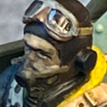
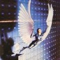
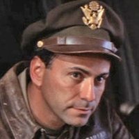
Here is the first of two pilots we are producing for the new 1/24 Hellcat release by Airfix. US Navy/Marine pilot in flying gear. Resin kit Sculpted by Robert Lane Box Art Edward Sage Available from the Elan13 Miniatures website Price: £20.002 points -

P-47D-25 & P-47D-30 1/32 Hasegawa
LSP_Ray and one other reacted to Miloslav1956 for a topic
Today update.2 points -
Some progress. I started with the cockpit and trying to get the canopy closed. It was posed open because the resin seats that were used were too tall to close! I removed these and made up the kit seats, then modified (i.e slimmed down) some surplus Academy crew figures to fit. Had to chop off the back seat driver's feet - this is normal for Trumpeter, they never seem to make their cockpits the right depth. Next was trying to get the canopy to pose closed, and after checking that the crew and seats fit with the closed canopy, I noticed a big gap down each side. I tried first to remove some offending PE on the back plate that I thought was blocking it, but then I needed to take away a fair bit of the notches on the back as well as a bit of clean up where it meets the front windshield. This is the best I came up with - a near 1mm gap on one side, and 0.5mm on the other: I will add a shim to the bottom of the canopy and reshape to fit, seems the best option. Also took the windshield off and cleaned up the glue join, then noticed there's no HUD! So I'll scratch one up next. May add some more detail to the cockpit, its pretty bare, but want to get cracking. Next is fixing those wings....2 points
-
Any Tamiya 1/32 rumours?
Out2gtcha and one other reacted to Thunderbolt for a topic
https://drawingdatabase.com/lockheed-p-38-lightning/ If you make one key assumption, then we can use math to determine the scale of the kit based on this evidence The assumption is that the width of the square on which the 5 is moulded is the same size in all of Tamiya's previous LSPs and that it would remain the same size for this future release. Then, knowing the wingspan of the p-38, which is 52 feet, you can calculate the approximate width of what the nose cone should be by dividing the relative widths of the nosecone piece to the wingspan, multiplying by 52, converting to mm, then diving that quotient by 32. You need to use a blueprint, of any size, to do this. for example, https://drawingdatabase.com/lockheed-p-38-lightning/ So then using that blueprint of the head on view of the a/c: Approx width of real nosecone, in mm = (nosecone measurement on blueprint ÷ wingspan measurement on blueprint) * 52 feet * 12 inches/foot * 25.4 mm/inch then divide by 32 to get the width of the nosecone in 32nd scale then calculate how many "5 squares" would fit the width of the nosecone if it were 32nd scale vs 48th scale we just need people to chime in with the widths of the "5" on the sprue of their Tamiya LSP kits; I do not currently have any for comparison. If they all end up being the same, then we should go full gas with this calculation.2 points -
RF-8G Trumpeter & Fisher Model
Starfighter and one other reacted to EricF for a topic
Hi, The Station 1 is done and ready for detailing2 points -
Hello everyone... Sorry for not being active here for a long while now. Surgery and recovery had to take the upper hand in life for the past month. The surgery i did beginning of April was successful, surgeons cut some of the shoulder bone off and reshaped and shaved some others and i got my ligament stitched back. Recovery is still ongoing and relatively smooth and i am quite surprised at how quickly i regained full range of motion, like somebody had removed a 'stop' from between cogs of a mechanism. Physiotherapy is ongoing and will continue until mid June when i am hoping to be released again to go fly. I got a bit tired from staying home in Beirut with all the hustle and bustle, and friends being at work all day, my daughter busy with school and not much to do, so i got the green light from the therapist and got on a plane and flew back to Doha under the guise of having to check on the apartment. In reality i was in need of a bit of peace and quiet and use the downtime i have at the bench to push on with the albatros build. I haven't managed to achieve all i wanted in the timespan i had allocated but alot has been done. I have noticed that the stretches i spent at the bench daily during my 9 days here has brought back some pain which i suspect is because i was overusing my right shoulder. Apparently it hasn't completely healed like i thought and this is why i suspect the doctor gave me the sick leave till mid June. Either way, i am back on an airplane tomorrow morning to fly home to continue with the treatment until my sick leave ends so no more benchtime until then. I am hoping to use the time i have for another model related project though! Well, back to the Albatros in no specific order. To be honest i don't exactly remember where we left off but vaguely at the engine. So on with that. I had scratchbuilt the valves by wrapping thin wire to shape on a conical sander. Added styrene punched discs for the valve spring covers. I had rummaged through my ww1 aftermarket stash but i had run out of Taurus resin valves and overhead cam so i ordered some online. By the time i came back to Doha they were there but i then realised i had ordered the set for the mercedes D3 and not the D3a where the rocker arms are at a different position so i ended up using the contraption i had built. Taurus resin spark plugs and modelkasten rubber thread was used for the plug and attachment. I used albion alu tubing for the distributor tube and ezline for the tube to magneto connections. I used Meng styrene hex bolts to close off where the priming cups are installed (or not) as i decided to have them not present on the kit i was building. The intake manifold was partially enhanced with scratchbuilt items. I used teflon tape due to its thinness to simulate the asbestos wrapping and used lead sheet to simulate the top covers on top of the intake manifold. The covers where left in their natural state with no painting done to those. I formed straps using the same lead sheet and used Meng styrene bolts to tie the straps together. The engine got most of its piping and ancillary wiring done using different gage fly fishing wire. I also added half the assembly of a Taurus models resin priming cup to simulate the drain at the top of the air pump on the front of the engine. Engine was painted using different alclad colors, tamiya colors, weathered with oils, some salt fading and prismacolor pencils (starting to become my favorite way to add little subtle scratches short of chipping the thing). The guns are the Master models brass jackets. As usual the photoetch was a nightmare but i got used to the sequence of assembly so i had the guns completed in half a day. The jackets got burnished in the Ammo Mig liquid along with the pe fret. Assembly is a bit tricky. The gun bodies got painted alclad gunmetal then drybrushed with buffable iron from Mr metal color Gunze and buffed and then another drybrush of silver to the edges. I weathered the guns with oils, and did some basic heat staining to the jackets with hotmetal sepia from Alclad. a quick dash of semigloss from mrp gave a nice sheen to the gun bodies. The wings got the Aviattic lozenge treatment and boy oh boy how i love Richard's products. The wings really look like fabric and every time i use them i have a big smile on my face. They are not the easiest but of late i have found that a hairdryer does magic on decals in general. The wings got the anchor points for the turnbuckles completely sanded away and marked for reference and then the new ones installed but more on that below, and all the hatches sanded and removed. I scribed the line where the wing to stub is connected (in reality the wing slips on the wingstubs) as wingnut wings represents this as a raised line. The wings got painted white with the area around the topside ribs shadowed and the ribs themselves darker at the bottom. Glossed. Decals on. A filter of sand brown was put on and it changed the tint of the wing to a nicer richer brown. I also added different filters in different areas to give some variation making the inner side darker. Sealed everything. PE hatches from a spare albatros HGW pe fret were used for all the hatches and i drilled them and will add photoetch fasteners to the hatch covers once i finish all the rigging. i preinstalled the regular type C metal gaspatch turnbuckles which are no longer produced unfortunately (they switched to resin and to be honest i don't know what to think). I added Micromark resin rivet decals for the nailheads around the wingstubs as they are more pronounced that the HGW ones and it helps show them in a small area like this. I also added some sort of drain pipe that is visible on a photo, from the fuselage on the right down to the wing stub. Now the meaty part. In relation to the mounting points for the turnbuckles on the wingstub. Let me first explain how the anchor points work as far as i personally understand. The Turnbuckle has a ball shaped end and the ballshape end in held down by a dome with a slit. My friend and fellow ALM Studios member Imad designed the cad drawings based on the dimensions and limitations of the SLA 3D printer. Working at this small size tuned out to be quite difficult with very little tolerance. We initially tried to work with a thickness for the dome that kept everything in correct proportions but we kept getting a dome that wasn't walled correctly so end of the day we printed the parts the smallest we could go. Back in doha i tried them on the wing and found them to be too big to my taste. Thinking it over a friend of mine tossed around the idea of burnishing tin from a coke can into shape and doing the base out of styrene. Brilliant, i love when modelers get together over a problem and find solutions. Next day i tried but to be honest i wasn't really satisfied with the strength of the burnished dome can so i went back to the drawing board. For the base below the dome, i wanted to do two sheets of styrene cut to size with the upper dome holes punched and the lower sheet with wider dome holes to be able to leave a lip on the dome so it could rotate freely in the base assembly and be locked between the wing and the top sheet of styrene that makes up the base. Another problem is as hard as i tried i wasn't able to get a consistent replication of the base styrene pieces in terms of hole alignment, corner curvatures and sizes. Back to the drawing board and lightbulb moment. I decided i was going to use the silhouette plotter for the base and i was going to thermoform styrene for the domes. I vectored the base shapes and surprisingly the silhouette plotter worked a treat without a hitch. The thickness of the sheet styrene was quite thin so i reckon this helped. I dont think it would be any good say on thicker styrene other than to scribe but then youd have to cut the parts out yourself. I also built a jig out of thick styrene which i drilled at 2mm and thermoformed domes by heating styrene sheet and burnishing it while soft into the jig. The domes just popped off with a good push with a beading tool. The domes got then the slit cut out using a sharp exacto blade and the domes slipped under the two sandwiched base styrene 'slices'. I added 4 bolts from Meng and omitted the two bolt outboard and front and back where they might interfere with the function of the turnbuckles. I hope i was able to clearly explain what i did. Added the drain tube for the fuel tank at the bottom from two albion tubes and a valve handle from bent brass rod Beyond that point, but not in the photos in tonight's update, i already painted and weathered the struts, installed them, installed the engine and the oil tank and wired it, the landing gear assembly was attached and rigged and i added the anti chaffing disc between the rigging lines from punched disc and the radiator was painted. I also painted and weathered the Rexx exhaust and basically i am left with the top wing job and the rigging and we can see this build through but that will be in the timespan of a month when i am back at the bench and at work here in Doha. The photo posts are going to be a bit on the heavy side but i do hope you enjoy tonight's update! I thank everyone again for the well-wishing notes you left and for the kindness. Stay safe and as always happy modeling Karim2 points
-

Any Tamiya 1/32 rumours?
D.B. Andrus and one other reacted to CyberGolem for a topic
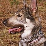
Its maybe sacrilegious to admit and it won't happen, and people will get red in the face for me even mentioning it, but I'd love to see some armor in 32. Decent kits too, not rubberband tracked snap-togethers. If Tamiya—or anyone else for that fact—did this I'd buy whatever they'd be willing to press out. At the least, I'd like to see the Hind-D in 32. Actually any of the giant or killer choppers for that fact.2 points -
Ju 87 B2 Stuka 1/24
sandokan and one other reacted to josebagasteiz for a topic
That's how I drive the engine. I added some hoses with fine electrical cable.2 points -

Fokker pair 2
bstachel and one other reacted to sandbagger for a topic
Hi all, Well the fuselage is completed, apart from fitting the engine exhaust and the propeller. The Rudder and Elevator control runs have been connected with the turnbuckles under the pilot's seat. Also the tail plane to fin bracing cable. The entire fuselage has been weathered and sealed. So now it's on to the lower wing, followed by scratch building the skeletal undercarriage assembly, which unfortunately is not available as a 3D printed part. Mike2 points -

me 262 with orginal engines set for restoration
Rick Griewski and one other reacted to TonyT for a topic
Just as well, the engines lasted hours.2 points -
Lt.Col. Maxwells BUSTER - FINISHED
LSP_Kevin and one other reacted to blackbetty for a topic
these parts will fit the Kinetic/italeri kit with minor mods as it turned out. some heavy duty grinding by dremel is on order to make these fit size is pretty close2 points -
I aplogise in advance that there will likely not be many pics, and what there are will be poor quality as the only camera I possess is the one on my phone. Money is tight atm, so this will in all probability not change in the forseeable future. Well, first baby steps. I spent the day yesterday playing with my new toy, a Paashe Talon. Very nice it is, too. Allow me to introduce parts C1 and C2. These two innocent pieces of plastic are going to get painted, stripped, scribed, riveted, filled, gouged, re-filled, painted and stripped (again) and generally will be horribly tortured over the coming weeks, poor things. I have to say, I'm impressed by Vallejo's Model Air paints. They've put up with my ineptitude very well, so far, and I was impressed with how little paint was required to get the white to completely cover the black in the test above. I also managed to get some paint (brushed Hannants' Xtracolour, for those who are interested in such details) and even some tiiiiny decals on the cockpit sidewalls: More later...2 points
-
Miniart 1/35 Focke-Wulf Triebflugel interceptor - Nachtjager version announced
wunwinglow and one other reacted to Out2gtcha for a topic
I sincerely wish Tamiya would have just started off with the obvious; make their armor scale stuff 1/32nd, and not that other scale. It would have solved every single issue ever discussed about the problems between the scales really. Obviously just barking at the moon here, but the benefits of it would have been enormous, and the drawbacks of 1/35th having never existed at all, would be completely moot.2 points -
.thumb.jpg.f0920d798d5d8600fb58b1d8a906ddff.jpg)
Any Tamiya 1/32 rumours?
LSP_K2 and one other reacted to shadowmare for a topic
Plot twist2 points -

Miniart 1/35 Focke-Wulf Triebflugel interceptor - Nachtjager version announced
Jack and one other reacted to Dave Williams for a topic
To be honest, since it isn’t “real”, no one is going to know whether it’s 1/32 or not. I understand there was a design and it might have gotten to a wind tunnel model, but I don’t think it’s going to look undersized when put on a table with 1/32 aircraft.2 points -
Dayyuumm, that is cool! I love stuff like this, and you nailed it! Now you just need to build the factory around it....2 points
-
RF-8G Trumpeter & Fisher Model
Starfighter and one other reacted to EricF for a topic
Hey, This evening I have started to "fill the gaps". After having taken this challenging decision, I feel more comfortable now. Honestly, when you start to drill the fuselage, you only hope that you thought about everything before on how to challenge the scratch built after. Thanks Ben for having pushed me on that way. I will probably open the door of the station 4 ; the aft one here below. Cheers Eric2 points -
1/24 Hellcat pilots from putty to retail items
Starfighter and one other reacted to elanlane13 for a topic
After a long delay, here Is the first of the finished pilots. US Navy pilot, painted by Edward Sage. This figure is now available. I'm waiting for the box art for the FAA Pilot to arrive from New Zealand.2 points -

1/32 Trumpeter Su-27B Flanker
Tony T and one other reacted to pouikpouik for a topic
I get back to modelling with the old Trumpeter’s Su-27B. This kit stayed almost 4 years on the shelf with half work done. So I decided to finish it as soon as posible before I ruin all that I did before. It seems so hard to pull the trigger for my new enlisted project in 2019. This old kit nicely detailed fit well together but also presents some minor mould’s errors. Luckily, the decal sheet still in good condition and I have no problem to finish her. Su-27 is a big plane, compared to thoses from US like F/A-18F, F-15E, F-14s. It’s big, so it’s Russian. Here we go and I hope you, friends love her.2 points -
Thanks very much I did re paint the fuselage with airframe aluminum and I think the tone is more realistic... I was fitting wings and dropped one doing damage to it, two steps forward one step back...The wing has been re-glued, re sanded and should be (hopefully) ready for paint again soon The repaint on the fuselage;2 points
-
Update TIme so black basing.. im not entirely sold i like the effect i got on the yellow. im somewhat liking what it has done on the light grays but im pondering if its worth the effort and hand cramps!! i do have to say i did master my new Badger Krome by motheling and using this technique ! and i feel tons more confident now with my airbrush. Here is the bottom that i mentioned was done in my previous post fuselage wing And last night i spend 1.5hours applying RLM 75 on the uppper surfaces left wing rightw And as a bonus here is a sneak peek at my custom paint booth that i built in January. more on that soon under Thanks for following ! Cheers Neo2 points
-
Tamiya Factory Corsair *finished*
Alain Gadbois and one other reacted to Gisbod for a topic
Thanks guys It’s pretty much fallen together now, I’ve installed the engine and bay and the other appendages and it looks like a Corsair now. I can’t tell you enough what an amazing kit this is - go and buy one today! Still to do - the wing and attachment, and the ground equipment; no idea how I’m going to tackle that. Guy2 points -

HobbyBoss B-24 Liberator
TenSeven reacted to RAF Liberators for a topic
Hey folks, I'm normally a lurker here, I don't tend to post outside of my regular sites just read other peoples stuff. But I've been told I should post this over here so here I am, cap in hand showing you my finished bird. It's out the box and yes I'm fully aware of all the shortcomings of the kit, Davis Wing, Turrets yardy yar etc etc I've put Master Model Barrels on it and some RB belts, not that you can see them, but other than that she's El Naturel Finished in Alclad, Gunze and Ushchi metal powders, weathered with Mig products. Thanks for looking and be gentle......... Gary1 point -
Started the Avenger with a crapload of PE....mix of soldering parts and CA.1 point
-

Any Tamiya 1/32 rumours?
alanash1963 reacted to Bill M. for a topic
I see reports on someone’s Facebook page that a computer screen with a cad drawing, clearly showing a P-38 nose along with the accompanying sprue was seen and photographed on a Tamiya factory tour. The photograph was part of the post. If true, was it 1/48 or 1/32 scale. Of course, now I can’t find it. Will keep looking. Is anyone else aware of this? Bill M. EDIT: I see this is already being discussed! Don’t know how I could have missed this! Sorry about the duplicitous post!1 point -
Wow, Very nice.1 point
-

F-104D Starfighter - 57-1315 - AFFTC Edwards AFB, 1960
Bill Cross reacted to Chek for a topic
Cheers Bill, I did take a look at your build on Brian's suggestion and think you've nailed the Norm 76 scheme. But - and bear in mind I've not seen these Luftwaffe schemes in real life, just photos - my impression is the Norm 62 scheme undersides are more silvery. In the examples below, both taken in bright light, the upper photo of the Norm 62 scheme looks more metallic, to my eye, while undersurfaces of the Norm 76 in the lower photo look more grey. . I liked the effect that Danny got on his build, seen below which also looks more metallic. He's used the Mr. Paint RAL 9006, which coincidentally is the brand I'll be using for the olive/grey/orange, but it seems nobody has it in stock over here, at least without a ludicrous shipping charge. I just hope the end result matches my expectations!1 point -

Miniart 1/35 Focke-Wulf Triebflugel interceptor - Nachtjager version announced
CATCplSlade reacted to D Bellis for a topic
The blades were articulated to alter their AoA and consequently the thrust angle of the ramjets to regulate speed and/or lift required (depending on the mode of flight). Normal elevons and rudders on the cruciform tail were to provide directional control. Deeper technical aspects are detailed in a few books written by David Myhra, Roger Ford and others. Source of skepticism or not, the Triebflugel (translates as "Thrust Wing") did get as far as wind tunnel testing during WWII. It along with Heinkel's two VTOL projects (Wespe & Lerche) directly resulted in post-war US VTOL experiments: Lockheed's XFV 'Salmon' and Convair's XFY 'Pogo'. The reality is that the aerodynamics of flying and controlling it had already been worked out on paper. However, as with the two US developments flown post-war, the two ultimately insurmountable issues likely would have been 1) Prodigious zoom-climb when transitioning from level flight to vertical attitude for landing, and 2) Lack of rearward visibility for orientation while landing. HTH, D1 point -
Hasegawa P-40E tweak list
Model_Monkey reacted to thierry laurent for a topic
Here it is at last. Please feel free to comment and to correct possible errors. I'll made the three other ones in the following weeks. I realized I never published the Hasegawa Spit Mk VI one I made some years ago. Even if I did not fully checked some aspects, is there any interest in this one? Curtiss P-40E TWEAK LIST TYPE: Curtiss P-40E Warhawk SCALE: 1/32 COMPANY: Hasegawa KIT Number: ST29 MOLD CREATION DATE: 2008 TWEAKS LIST VERSION 1.0 (publication date: November 2010) Compiled by Thierry Laurent. The following list is intended to help modelers in improving scale accuracy of an airplane model replica. In no way is it intended to support or be offensive towards a scale model company. As such, it is only the result of a progressive process and is in no way intended to be absolute or even comprehensive. Hence, it is intended to focus on commonly admitted discrepancies and will probably not cover some errors. It is up to the modeler to decide whether correcting the listed issues is worth the time and money he will have to invest in the quest for accuracy process. No aftermarket correction or detail set is mentioned in this document as the availability of such items may be very variable. Hence, refer to other LSP sections to find relevant information. Moreover, aftermarket sets do not necessarily correct all listed issues. Please refer accordingly to relevant documentation. 1. GENERAL REVIEW • Kit is made of light gray plastic. Fit is generally excellent but average or even very bad for some specific parts because the kit has been broken down so as to facilitate future production of the long-tail P-40 variants. Its shapes & dimensions are correct and the details are generally accurate. 2. FUSELAGE (from front to rear) • A line of prominent rivet heads is missing on the internal front edge of the radiator air intakes. • The fit of parts M3 & M4 is very bad. This asks for CA glue, a lot of sanding and restoration of the engraved panel and rivet lines. • The fit of the exhaust support panels (D1 & D2) is far better but check closely before gluing as a very thin plastic shim behind the part may be required to keep parts flush with the fuselage edges. • This kit release only has the early tubular-shaped exhausts whereas many P-40E airframes used a fishtail shaped type. Exhausts parts are nicely engineered. However, do not remove them from the sprues too early as it is not easy to differentiate them. Here is the best approach: cut each exhaust half and glue it immediately on the other half which is still on the sprue. Let the glue dry and use a drill or a rat tail file to get thinner edges. Paint them and finally remove each complete exhaust from the sprue to glue it on the painted airframe. • Hasegawa instruction sheet clearly shows the nose panel lines that shall be filled in as they only appeared on later P-40 marks. Do this cautiously as it is a little bit tricky to fill and sand without damaging adjacent detail. This is particularly the case for the panels located under the exhausts. • The kit gunsight shall be replaced by a photoetched one even if such parts are generally too thin to depict correctly the scale thickness. Replacing the bead sight pole with a correctly shaped metal replica is recommended as well as the kit part is very fragile. • Open dove-tailed belly cowl flaps are correctly depicted. They are a little bit too thick but the amount of work necessary to replace them with photoetched ones is important to get a marginally better result. Sanding a little bit the edges of the plastic part A4 is probably the best solution. Styrene actuating arms (Q1, O27 & 28) are delicate and cannot be thinner. • Add a spacer (e.g. a sprue section) between fuselage halves (at the Karman rear root level) to avoid getting a too large seam between the fuselage and wings. Alternately, glue the upper wing halves to the assembled fuselage sides first then add the lower wing. • The fuselage parts K3 & K4 located under the rear windows shall be glued in each fuselage half to avoid problems. The small gap on the upper edge shall be filled when the fuselage halves are glued together. • The kit has the little blue navigation lights (V7) used on the early P-40s (up through the P-40D model). However, as they were not used anymore on P-40E, glue them, fill the joint and sand them smooth. Do the same with the V4 parts. • The choice to use separate parts for the tail is the consequence of the release of later long-tail marks. Note that the seam does not correspond to a panel line. Unfortunately, if the fit is rather good, the rivet and panel lines of both sections do not fully correspond. To avoid alignment issues, it is recommended to glue each half tail with each half fuselage. Use CA glue to fill the seam, sand cautiously and engrave damaged panel and rivet lines. • Elevators are not separate parts but this is not a problem as wartime pictures generally show them in a neutral position. The tail fin is separate and may be modified to be slightly angled, should you wish. 3. WINGS • Fill the hole in front of the starboard landing gear knuckle (intended for the clear part V3). • MG wings fillets are separate parts (A8 & A9). This choice was probably done to facilitate molding of MG muzzles (holes in the ends of the gun blast tubes are nicely molded) and possibly to release lightweight P-40 marks initially released with four MGs. However, the fit of the MG muzzle part in the wing leading edge is not excellent. Try to get the best fit on the wing upper side. • MG ejection chute holes are not fully opened. Either drill them or simulate the paper sheet used to close them on some Warhawks and Kittyhawks. • The flaps are accurately molded up. 4. COCKPIT • The cockpit is accurate but simplified. Note that in practice, there are few visible components except the IP and the seat. • Instrument panel is magnificent and needs few improvements (update the lamp and the large knobs on the lower section). Do not forget adding conduits on the back of the panel instruments. • The pit sides are too simplified: remove electrical conduits to replace them with solder or copper wire, update the too simplified throttle and add small details here and there. • The seat is disappointing: it is correctly shaped but the strengthening ribs are missing on the sides and the reinforcement plate on the back should have been a separate part. Moreover the sides are far too thick. Updating or replacing the seat with an aftermarket one is recommended. Note that the kit has no seat belts. • The large bolt heads on the rear armor plate K2 are undersized and too shallow. • A series of large bolt heads is missing on the central axis of the floor (they were presumably used to secure both wings together). 5. CANOPY • The windscreen in the initial P-40E release had a fantasy frame line engraved on each side of the part. Take care to remove them as the operation may easily result in a flat in the windscreen or in distorting plastic transparency. • Two sets of canopy parts are provided for either an open or closed canopy. Note that the two sections do not have the same width as the larger one is tailored to drop onto the dorsal spine (for an open canopy). In either case, check if the little triangular doublers at the base of the windscreen edge shall not be sanded off as they were not present on all P-40E models. • The canopy rail mechanism (with its pulleys on the starboard side) is missing. 6. LANDING GEAR • Landing gear struts are correct and well detailed. Simply add hydraulic fluid brake hose on the main landing gear legs. • The wheel wells are correctly detailed. The kit has no factory-set canvas wheel well liners. Note that many airplanes had small bolt holes on the round edge of the wheel wells. Hence, choose how to model that area of the airplane according to the airframe you want to replicate. Two holes shall be drilled in the landing gear rear side (part A17 & A18). Some missing hydraulic lines and hoses shall be added as well but keep in mind the P-40 wheel wells were very bare. • Drill the two holes in part A30 & A31 to get more depth. 7. OTHER REMARKS • Hasegawa cleverly molded the windscreen part with the forward deck to eliminate the usual gap problem between the clear part and the fuselage. A similar approach is used for the rear windows. • Kit gives optional separate clear navigation lights. • Kit gives a US 500 lb bomb as external war load option. The bomb fins and spinners (O25 & 26) shall be thinned or replaced with thinnest plastic card copies or with photoetched parts. • Kit also gives a centerline drop tank with optional fuel caps. Note that the molded cap is not circular because of the mold angle. Either rebuild it, replace it or use the other cap (O6). • An optional gun camera is also offered. • Tires and wheel hubs are separate parts to facilitate the painting job. • Kit has a very detailed (8 parts) life-like seated pilot figure. • Note that some parts marked as “not for use” on the instruction sheet may be used if you want to depict some other P-40E variants (e.g. gunsights, cranked pitot tube, etc.). • This release has decals for two USAAF schemes: - PTO, New Guinea, 9th FS 49th FG, Lt John Landers, 1942 ("ET601") - CBI, 76th FS 23rd FG, Maj. Edward Rector, July 1942 ("104") The following sources were used to build this list. Modelling essentials: • Bridgwater, H. C., The Curtiss P-36 and P_40 in USAAC/USAAF service 1939 to 1945, Scale Aircraft Modelling Colours, Combat colours n°3, Guideline Publications, 2001. • Drendell, Lou, Walkaround P-40 Warhawk, n°8, Squadron Signal Publications, 1996. • Ehrman, Vlastimil, Roman, Valerij, Curtiss P-40, MBI, 1998. • Kinzey, Bert, P-40 Warhawk Part 2, Detail & Scale Vol. 62, Squadron Signal Publications, 1999. • Sembrat, Pawel, Kittyhawk I/IA, Model detail Photo Monograph n°14, Rossagraph, no date. • Wieloczko, Leslek A., Zmuda, Tom, Curtiss P-40D/E Kittyhawk MkI/IA, Kagero, 2008. Other used books • Dann, Richard S., P-40 Warhawk, In Action n°205, Squadron Signal, 2007. • Darling, Kev, Curtiss P-40 Tomahawk/Warhawk, Warpaint series n°77, Warpaint books, 2010. • El Bied, Anis, Laurelut, Daniel, Curtiss P-40 de 1939 à 1945, Histoire & Collections, n°3, 2006. • Ethell, Jeffrey L., Warbirds of World War II, Crestline – MBI Publishing, 2003. • Green, Brett, Modelling the P-40, Osprey Modelling, Osprey Publishing Limited, 2005. • Gronczewski, Tomasz, Przemystaw, Skulski, Curtiss P-40 Warhawk, ACE publication, 1993. • Janowicz, Krzysztof, Wieliczko, Leszek A. Curtiss P-40, Vol. 1, Kagero, 2008. • Janowicz, Krzysztof, Curtiss P-40, Vol. 2, Kagero, 2009. • Janowicz, Krzysztof, Curtiss P-40 cz. 3, Monografie Lotnicze, n°66, AJ-Press, 2001. • Mc Dowell, Ernest R., Curtiss P-40 Warhawk, In Action n°26, Squadron Signal, 1976. • Molesworth, Carl, P-40 Warhawk Aces of the CBI, Osprey Aircraft of the Aces, n°35, 2000. • Molesworth, Carl, P-40 Warhawk Aces of the Pacific, Osprey Aircraft of the Aces, n°55, 2003. • Molesworth, Carl, P-40 Warhawk Aces of the MTO, Osprey Aircraft of the Aces, n°43, 2002. • Rys, Marek, Curtiss P-40 cz. 1 Tomahawk/Kittyhawk, Monografie Lotnicze, n°64, AJ-Press, 2000. • Rys, Marek, Zbigniew, Kolacha, Curtiss P-40 cz. 2 XP-46, XP-60, Monografie Lotnicze, n°65, AJ-Press, 2000. • Szlagor, Tomasz, P-40s of the Mediterranean, Air Battles n°01, Kagero, 2007. • Thomas, Andrew, Tomahawk and Kittyhawk Aces of the RAF and the Commonwealth, Osprey Aircraft of the Aces, n°38, 2002. • Wagner Ray, The Curtiss P-40 Kittyhawk I-IV, Profile, n°136, 1971. • Zbiegniewski, Andre R., Nowicki, Jacek, Curtiss P-40 Tomahawk/Kittyhawk/Warhawk vol. 1, Wydawnictwo Militaria, n°104, 2000. • Zbiegniewski, Andre R., Nowicki, Jacek, Curtiss P-40 Kittyhawk/Warhawk vol. 2, Wydawnictwo Militaria, n°122, 2000. Other references: • Some magazines articles (more particularly from Replic & Scale Aircraft Modelling) • Some web pages (more particularly LSP & www.p40warhawk.com)1 point


.thumb.jpg.cd22b958c9e88a898a21e18b862c523e.jpg)