Leaderboard
Popular Content
Showing content with the highest reputation on 04/15/2019 in all areas
-

1/32 Kitty Hawk F-5E Kicked Up A Notch. Oct 3/19. Finished!
jgrease and 12 others reacted to chuck540z3 for a topic
April 14/19 I finally finished the wings, including the control surfaces. As with everything else, every panel line was re-scribed and every rivet re-punched. I bet I’ve redone about 2,000+ rivets by now, but after a gloss black paint finish, it will be well worth it. The wing to fuselage fit is not very good, but by sanding and dry fitting many times, you can get the fit close enough that you don’t need much in the way of filler. Here’s how I did it: 1) Sand and dry fit the wing to the fuselage to get as close a possible to a perfect fit. 2) Apply Tamiya Extra Thin Cement (TETC) to the main portions of the wing to fuselage, then hold the parts tightly together with your hands until the parts are fused. This takes about 5 minutes and don’t worry about getting glue to all portions of the join. 3) Apply a good bead of TETC along the entire wing to fuselage join. This not only adheres the wing, but it makes the plastic swell, helping to close small gaps. Let it dry for 1 hour, then apply another bead, both top and bottom. You want to use lots of glue, but not so much that you make the plastic too mushy. Let it dry for 24 hours. 4) Sand the join smooth with #1000 grit sandpaper, removing any excess glue marks on either side of the seam. Remove the sanding dust. 5) Apply thin masking tape to either side of the seam, leaving a small gap no bigger than what you need to fill. 6) Thin some Tamiya Basic putty in a small jar with Tamiya lacquer thinner. Since the putty smells exactly like the thinner, I bet it’s the very same stuff. With a microbrush, apply the thinned putty along the seam. 7) Using a Q-tip dipped in more Tamiya lacquer thinner, swipe along the seam to push the putty into the gaps and smooth the overall surface. You want the putty to be slightly raised from the join, because it will shrink. 8) Carefully remove the masking tape, which should leave a straight bead of slightly raised putty. Let the putty dry for 24 hours. 9) Sand the join smooth. If you still have small holes and gaps, redo them with more thinned putty. 10) For a final sealing micro-filler coat, paint on a thin bead of Future/Pledge on the seam and let it dry for 24 hours, then sand. If you want to redo some areas, just apply Windex to a Q-tip or rag and remove it. Now some pics. The flaps and ailerons are just dry fitted and I will paint them separately for ease of handling. The fit on the bottom turned out pretty good too. The gear wells were painted before I glued on the wings. Now an often-ignored part of modeling wings. The trailing edges of wings in most kits are too fat and they should be sanded down to thin them. The ailerons in this kit do not fit the wings at all, so you need to sand each hinge down about 25% in order to get them to mesh properly. Based upon most reference pics of parked F-5’s, the rear flaps are usually straight while the ailerons are drooped down, while the front flaps can be straight or drooped down just slightly- which is how I’m going to pose them. As somebody mentioned already, this is starting to look like a jet! Thanks again for your comments and interest in this build. Cheers, Chuck13 points -

Tamiya's 1/32 Mustang and Corsair, both B&W
Biggles87 and 9 others reacted to Fancherello for a topic
hello I'm working on a pair of Tamiya's superb kits: a Mustang and a Corsair, both being built together as a Black&White project. I've been waiting a biy before sharing those as I wasnt too sure how this would turn into. The Corsait will probably be Ira Kepford's second Corsair which is very well pictured on both sides, the Mustang will be the famous Lou IV both for the fun of tackling the blue/green color issue on my way and because this plane and his famous pilot had their fatal fate not very far away from where I live. The Corsair has been started by using Brassin's set, the pit is superb, the engine too...but i'm making a step back with the latter as it doesnt allow a clean closed display with the provided cowlings. I'm now working on the kit's engine and will keep the Eudard one for a separate display. I've added a HGW harness set that I've been whitening to keep in the topic. I've been working on the Mustang the same way with personal work on he engine: casing texturing, wiring and bits. I also worked the wings and tried to replicated some worn puttying by working layers of surfacer. I used two tines of surfacer to help controlling that. As sanding is feathered, actually filled rivets extend a bit further that the surfacer color. The cockpit is done with some Barracuda add ons and I used some RBrinzan's etched templates for the floor. so now I'm working on the Corsair's kit's engine and the Mustang wheel wells ! bye Fanch10 points -

Ticket to nowhere - He162 departing
R Palimaka and 9 others reacted to Wackyracer for a topic
New little sideline project whilst waiting for paint to dry/things to arrive on the Liberator. Spent the afternoon assembling the railway gondola to check the He162 fitted!10 points -

Airfix News Just in from Telford: 1/24 Hellcat!
Michael931080 and 9 others reacted to airscale for a topic
just to say the cockpit set is finished & will be available by the end of the week ..more here Airfix have May 2019 as the release date for the kit TTFN Peter10 points -
thanks folks the decals just arrived, so the test shot was remade and this is the final production version - I think it is our best set ever & I am quite proud of it can't wait for the kit to come out now.. ..they will be available on our website and with retailers by the end of the week @ £18.95 TTFN Peter7 points
-
afternoon ladies just a quick update on the panel skinning on the P51 - not much to show panel by panel, as the process is pretty much the same but the lower wing is almost complete so time for a few pics.. ..the C model has quite a large outlet for spent cartridges and a chute assembly that can be seen through the hole, so first up is the panel and the chute.. ..I don't really know what the little slots are for - venting maybe.. ..the two were assembled and a hole routed into the wing to make room for it.. ..the panels that define the shape of the gear door opening were done next, with some structure along the edges the doors sit on when closed.. ..and this is where it's at... ..the panel behind the gear opening will be left until all the filling of the leading edge is done as it has domed screws and is left natural metal as seen below and if I add it now these will likely get damaged by the sanding / prepping process.. ..lower wing done otherwise.. ..will do the upper wing next and I am on leave all this week so hope to get lots of it done.. TTFN Peter7 points
-

PCM Macchi 200 in 1/32
Model_Monkey and 5 others reacted to baffozac for a topic
My Macchi 200 built with a little help from my friends and months of patience, most of the parts had to be scratched : For example the engine.6 points -
Hi all - long time, no speak! I've mostly been pulling my hair out trying to get the canopies to look OK in the closed position - originally I was just going to have both canopies open, which would have been a lot simpler! Booked today as holiday so I could immerse myself in the canopies. The master patterns have now been through a large number of tweaks and re-shapes to get something that looked OK - the tricky area being the fit of the rear sliding section to the tunnel between the cockpits. Once happy on with some test mouldings I then had to get some fresh mouldings I was happy with - again!! So - here's were we're at - some good mouldings (I noticed earlier there is actually less optical distortion in my vac mouldings than there is in the front sliding section - as provided by Mr Tamiya!). The tunnel section has been bonded in place - and filler applied along the joint ready to blend in once dry. The rear sliding section has had stretched sprue 'rod' bonded in place that engage with the canopy rails and hold the rear sliding section in place now - both opened and closed. Some decal damage has occurred during this work, so I have a couple of Squadron Code letters to re-apply (fortunately I have spares). Model photos are on one of the circular base/clear dome combinations - and it fits perfectly... Hopefully some more progress over Easter weekend - I need to get this finished as I've got other projects backing up... Blue Skies, Iain6 points
-
1/48th Boeing B-52H Stratofortress
Greg W and 5 others reacted to tomprobert for a topic
I've been having a play withe the nose radome, which is more pointed on the later G and H models. This kit's nose is more like that seen on the A to early G model, so some surgery has been needed. I did consider slicing the entire nose off, but it actually worked better using the kit's nose as a starting point, and adding the basic shape of the extension using plastic card. The plans Sanger give were useful in doing this, and it didn't take long to replicate a more H-like radome shape: IMG_0916 by Thomas Probert, on Flickr IMG_0915 by Thomas Probert, on Flickr The gaps were then filled with Milliput and when dry, sanded to shape. When the plastic card formers begin to appear, you know you're close: DSC_0102 by Thomas Probert, on Flickr However, there is a problem, as I think the lower nose area (circled below) is incorrectly shaped and is too bulbous - it's almost as if the kit's nose is like a hamster with its cheeks full. However, there'd need to be some serious surgery to sort this - the kind of surgery that I'm not unwilling to take as I do plan to have this model finished sometime this century... Nose by Thomas Probert, on Flickr I've had a bit of a play with the camera fairings on the chin, and the look of the nose is improved with these in place. Note the canopy has not been trimmed to the correct shape as of yet, hence it sits too high at the moment: IMG_0951 by Thomas Probert, on Flickr IMG_0949 by Thomas Probert, on Flickr There's still some jamming pods and sensors to add to this area, and then I'll have a look at how it looks under some primer. Until next time, Tom6 points -
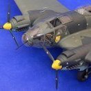
Last week I continued working on the radio's and the inside of the fuselage halves. Just a little more detailpainting and the fuselage halves are ready. I saw that it is better to glue the wings first to the fuselage halves before glueing the halves together. Before I can glue the winghalves together I had to dril the holes KH forgot. Then i glued the winghalver together. They fitted really wel. Below are the pictures of my work last week without further comments On the last picture you can see I still have to bend the belts. So far I am really enjoing myself building this kit and I wonder why there are so few people building this beauty. That's it for now. Thanks for watching.5 points
-

PZL P11 III “Cleveland” 1932 from scratch scale 1/32
Trak-Tor and 4 others reacted to Marcin_Matejko for a topic
Thank you very much The last weekend in Wroclaw took place one of the best modeling exhibitions in Poland. I presented there my PZL 11 model which I liked very much and got a prize award in this "best of show".5 points -

Any Tamiya 1/32 rumours?
thierry laurent and 4 others reacted to BiggTim for a topic
I already did. Twice. I have a box of diapers ready for when/if there is confirmation.5 points -
CONTINUATION OF MY 1:20 SCALE SCRATCH BUILT B17G (RADIO ROOM)
tomaszhajzler and 4 others reacted to fozzy for a topic
THE EQUIPMENT BENEATH THE RADIO OPS DESK Hi to all! Here is the next episode to this never ending saga! Before I start I want to say that I do realize that this scratch build is not 100% accurate.The interior colours I have chosen are a mish mash taken from hundreds of photos I have collected.The other problem is that it seems that The Flying Fortress's interior used different equipment and placed them in different areas of the aircraft....for example the Tokyo shut off valves. I have placed them on my model beneath the Radio ops desk ...which some of the G variants were... whereas other "Gs" had them on the aft bomb bay bulk head. This of course causes me confusion and I have to go one way or the other. At the end of the day I have to convince my self that this is my own interpretation of this glorious Aircraft and it's never going to be completely accurate and to exact scale as scratch building is really flying blind!! Reason why I am rambling on is because this project is taking so long and at times I feel that I have bitten off more than I can chew and I have to convince my self to carry on...regardless! ANY WAY.............................................. I have scratched all the bits and bobs that seem to be under the radio ops table although as I said ...difficult to know what was and wasn't installed!. ....but starting with the radio ops seat...here it is ready for painting.... here's the scale....... All painted with the seat straps fixed.... I have labeled whats what with the various equipment in the next couple of photos...the usual plastic scraps and wire were the order of the day!............. I attached the top section and tried to poke the camera through the back end and sides to get the shots of the equipment!.... I then glued the seat in position and took a few more photos...... OK....so that's that part done! I am going to go to the rear port side of the radio room now to scratch what ever I see in the photos I have! Thanks for taking the time to look in Fozzy5 points -
I'm not sure what the fairing on top of the main radome is Tom, but the Barksdale B-52Hs at Fairford last month no longer had them. The shot of 60-0024 is an example, but the rest of the detachment were the same. Picking a specific airframe and/or era for antenna/fairing combinations would likely be the best way to go. The Fighter Control website is an excellent source for aircraft visiting the UK, this article being but one example. But there are many more from previous visits over the years which a forum search will reveal, many including close ups such as that below. That skin could do with a good slathering of Nivea cream.5 points
-
I built a new gunsight based on the kit part. I drilled out the kit part, put a chrome disk in the bottom and made the lens out of epoxy tinted with Tamiya clear yellow. Scratch built the brackets and used clear acetate for the reflectors. Not exactly “correct” but it is what it is. Propeller. One of the big problems I have is that my hands aren’t steady enough to paint the camo scheme so I made masks which took a couple tries but it was time well spent. My test mule. Pay no attention to the colors, I just grabbed two colors to test the masks. If the model turns out this good I’ll be happy. The odd scheme on the cowl is unique to Wake Island Wildcats. The planes were painted on the carrier delivering them and the prevailing opinion is that they draped a cover over the engine and cowl so they didn't get paint on the engine. I'm going to try some pre-shading on the mule. Never tried it, just like almost everything else on this model.5 points
-
Ticket to nowhere - He162 departing
Shiba and 3 others reacted to Wackyracer for a topic
Found the photo that inspired me4 points -

DONE AT LAST! 1:48 Mauve P-40N "Lope's Hope"
D.B. Andrus and 3 others reacted to KUROK for a topic
Slow but sure progress. I practiced spraying Future until I was satisfied. Now I have an overcoat of Future on top of the decals. This will protect everything from oil based weathering to come next. Sorry for the messy workbench! Don't we always end up working in an 8 inch square? LOL4 points -
Finally got a coat of primer on but there were problems, of course. One I gotta’ own myself because the model sat on the bench for a couple weeks and picked up dust. No big deal, I’ll just wipe it down with some IPA and use a paper towel that someone told me is “lint free”. Long story short, It's not and I didn’t realize how much lint was on it until I started priming. So I had to stop and tediously remove all the lint I could fine, which went okay. THEN! My completely clean airbrush started clogging and spit out a few chunks. At this point I’m like “the hell with it” and soldiered on clearing the occasional clog. I knew the airbrush was clean so just to see what would happen I filtered some with an ancient filter funnel I’ve had for 40 years and sure enough the primer has chunks in it. Lesson learned. It could have been a lot worse but now I have to do some sanding to get rid of the problem areas. See those five dots in the filter screen? Those are chunks of primer and they do not pass harmlessly through an airbrush. I guess I’ll be filtering my paint from now on. Enough whining, this is what everyone seems to be waiting for. Comments and critiques are always welcome. Don’t be shy - an honest critique is a catalyst for improvement.4 points
-
It's the Tamiya 1/32 kit with the Eduard Brassin port engine, Xtracolor paints and Aviaeology decals. The aircraft represents one flown by Squadron Leader Vic Cherry, a Texan who flew with the RCAF's 418 Squadron.3 points
-
Oh, also some fuselage sidewall work.3 points
-
Ok for more pics, but as I started this it when it came out (may be more than 12 years ago) a lot of pics are not digital, as that of the engine, sorry. PCM Macchi 200 is a very good kit in shapes and dimensions, but for me, poor in details. Start at the front of the plane: The propeller hub: left part are mine, right the kit one. Copies in resin, if one day I decide to make another, not tomorrow ! The propeller: not perfect in shape and too flat. Down is the firing mecanism through the propeller, not in the kit. A coat of Alclad to verify the moulding The beginning of painting and weathering.3 points
-
 Thanks! I looked at the Vector engines long and hard, but in the end decided to improve the kit engines instead. The main reason being that the Vector engines don't appear to include the prominent exhaust pipes. I'll be scratching those out of either styrene or aluminum tubing (along with the inner wall of the collector ring). The main drawback of the kit engines is the shape of the crankcase at the base of the cylinders. The blockyness in that area can be improved by shaving off the high points. Not a perfect solution, but better than shelling out $70+ for a pair of engines that only partially fill the bill anyway. The real thing (also note the exhaust pipes extending forward): Lots of other details will be added to my engines along with the exhaust pipes to make them 'busy' enough for me. D3 points
 -

1/32nd Hawker Hunter F5 - April 14th
Chek and 2 others reacted to crobinsonh for a topic
These photographs show how I filed the vents and sanded them ready to have the "new" correct vents and grilles drilled and created on the model. Hopefully the "pictures" present a 1000 words and everything is clear from these.3 points -
'I don't really know what the little slots are for' I believe they are for ammunition belt links. Of all of the imagery I have studied, I don't recall seeing that return. Not only that, but in the next 2 photos, The dip in the ribbing makes an angle going backward, that is matched up to the angle of the skin. Good show, Peter. Nice capture. Sincerely, Mark3 points
-

Curtiss F6C-1, Curtiss F6C-2/3, Curtiss P-1A Hawk, Curtiss AT5/5A
BlackMikeModels and 2 others reacted to LukGraph for a topic
Curtiss F6C-1 U.S.Navy Fighter Fighting Squadron Two, USS Langley, 1926. Lukgraph 1:32 scale kit. Model built by Ryszard Holak. Wish you lots of fun! Status all Curtiss kits: available! Thanks Lukasz More: http://www.lukgraph.pl/?page_id=1213 points -
After sorting out the fit issue I went on to painting the whole thing. Well beforehand I wanted to clean up some flaws and cracked the whole thing. With a lot of patience and silent screaming the reconstruction was once again succesful! But I'm not gonna touch any flaws again on this beast! On to the better news: The frame itself recieved a coat with Gunze off-white. and I started the detail painting. While the frames are a light cream colour on all pictures, the cameras vary a bit. There are pictures of grey-green (maybe RLM02) cameras, dark grey with a RLM02 lens and somewhere I read something about a blue-grey camera colour. That's what I went with: Well I'm not 100% sure/happy about it. Has anyone more information regarding RB50/30 camera colours?3 points
-
Some work on the cockpit. What I have done is to cut up some old consoles from old kits or unused bits . I then sand them down to wafer thinness and then glue them to the new consoles. This isn't really accurate but it does give that "busy" look that I am after. IP. Flat panel with Airscale decals and bezels. Looks a little wacked in this large photo but will look the part when installed. A little work on the tip tanks. The metal tab will slide into a slot in the end of the wing. Dry fit of cockpit componets. Canopy and windscreen set in place. The windscreen that comes with the kit seemed too large. So I cut down an F-18 windscreen and sanded a flat spot in front....seems to work. Later, Dan3 points
-
Managed time to get a bit of paint on the cockpit. cheers Matt3 points
-
hi Mark M, yes this is no Tamiya but having started the Heller/Airfix E-3 Sentry in 1:72 until I started this one, I must say that this is an easier build, I am enjoying this one really. Once you overcome the stupidity of the inner parts 1 mm higher than its outer skin, then it something that can be solved. Thanks Markjames for the encouragement, I have to agree that once completed, the gear bay is the most elaborate of any kit I ever built. having put also the sides onto the structure, I wish I had sanded the sides of the front and rear faces of the wheel bays a bit more to ease the mounting of these plates, but in the end it has come together: around the wheel bay there is now just a small gap to deal with: also the bottom plate between the intakes now almost fits without a step, I think just a little more sanding of the surfaces of the intakes will solve this.3 points
-

Fokker pair 2
Greg W and one other reacted to sandbagger for a topic
Hi all, Well time to start the fuselage build with controls, pipework etc, Mike2 points -

WNW airco DH9
tucohoward and one other reacted to DrDave for a topic
Irish free state air arm, Fermoy 1923.2 points -
Copper state N17 in Printscale soviet colours.
Bill Cross and one other reacted to DrDave for a topic
2 points -

Any Tamiya 1/32 rumours?
thierry laurent and one other reacted to wunwinglow for a topic
Not in my house they don't.....2 points -
Now here's a funny thing!! As can be seen from this extract from the T-6/Harvard manual, the engine cowling comprises three parts: so I wonder why KH decided to make the model one four parts, none of the joints coinciding with the panel joins on the real thing: More sanding, more polishing!2 points
-

Trumpeter 1/32 Bf109K-4 review out yet??
Rick Griewski and one other reacted to rafju for a topic
Hi all From this time, is there any on line build for this trumpy K-4 kit (build thread)? Thank you Raf2 points -
Tamiya's 1/32 Mustang and Corsair, both B&W
Greg W and one other reacted to Fancherello for a topic
Hello an thank you ! Scratchbuilder : So far i've set one rule: interior green is my "middle grey" which is Gunze's.... RLM 75/H69. Everything else is done around this center point by photo inspiration. I've found that some Prince August Ivory white and Ak/Meng's black make a good matching combo for brush painting. This has been the first difficulty, because some blacks turn blueish or greenish when being lightenened. Now i've found how to stay in my center grey tone, things fo more easily. ( Gunze Aqueous are not easy to brush !! ) Lightenening and darkening the base grey for airbrushing has been more easy too. I've worked the wood floor, seat, znd other details just by logic, pics and inspiration. Pictures help but also tell very different contrasts and colors....so i let inspiration go. I have a good help too: i delibaretely chose two classical birds in two very well known schemes for a reason ( not the only one though ). You know whuch color is a mustang pit, you kniw which color is a Corsair's pit, you have a picture in your mind of how you'd render a wood floor, etc. All this is helping my thing tell the story, actually I think that the reader is making half the job unconsciously. This said we'll see how it turns on the airframes. And LSP-Ray....i'm not comfy at all !!! I find that very challenging too and i'm not sure hiw that will work in the end !2 points -
Wow, not seen this before, heard about the book, though not read it; Fifty Shades of Grey!2 points
-
 Just got my cockpits - fantastic! Well done, Steve!2 points
 -
 Thats looking really fantastic - very nice! Lots of other stuff to work on while waiting for that observers station You replacing or improving the engines at all?2 points
 -
1/32nd Hawker Hunter F5 - April 14th
Chek and one other reacted to crobinsonh for a topic
A few updates after taking the images from my visit with John from Britmodeller to see the incredible F5 at Tangmere. It looks like she is in the final inspection hall at Hawkers as she is immaculate. I had spent some time removing the Revell grills etc and either using Eduard PE or scratch plastic fins for the grills all of which was a complete waste of time and energy The first thing I did was to draw out a scale plan of where the vents for the F5 with the Sapphire engine are vs. the F6 with RR Avon that the Revell kit is based on. This then allowed me to draw where these would be on the Revell kit. Anything with an X through it is in the wrong place! Showing the other side. The following photographs from my trip to Tangmere show the reference I used for placement of vents and grilles.2 points -
That looks nice! Good job, D and MM!2 points
-
1/48th Boeing B-52H Stratofortress
daveculp and one other reacted to tomprobert for a topic
The fuselage is now joined - lots of tabs were added along the mating surfaces and on the whole, I've got a pretty good join. Considering the size of the parts, they matched well. As this picture shows, there'll still be quite a bit of filler needed (par for the course with these sorts of kits) but nothing of real concern: IMG_0906 by Thomas Probert, on Flickr The H-model tail turret has also been added to the rear fuselage: IMG_0907 by Thomas Probert, on Flickr I've also lined the openings for the undercarriage bays so they are more representative of the real aircraft: IMG_0908 by Thomas Probert, on Flickr IMG_0909 by Thomas Probert, on Flickr IMG_0910 by Thomas Probert, on Flickr So now it's out with the filler... Until next time, Tom2 points -
1/32 Kitty Hawk F-5E Kicked Up A Notch. Oct 3/19. Finished!
CarstenB and one other reacted to chuck540z3 for a topic
Thanks Guys! I have been asked how I use CA glue as a filler in the other forum, especially when panel lines and rivet detail is enhanced or restored. Although I’ve written tutorials on this subject before, I can’t find them, so here’s a new updated one that I will share here as well. Using CA Glue as a Filler I have been using Cyanoacrylate (CA) glue as a filler for many years and more recently, about 90% of the time over traditional modeling putties. I use CA glue on every single join of my models, to make sure there are no gaps to be found later. While putty still has its place, CA glue has the following advantages over putty: 1) Drying time is quick to immediate, especially if you use an accelerator. 2) Since it dries harder, it sands finer- but sanding must be done within an hour or two of drying. Left to cure overnight, it will become much harder than the plastic, making sanding difficult. 3) As a glue, it strengthens joins while it fills them. 4) Panel lines can be created or re-scribed over CA glue with a smooth finish, which you can't do with putty. Again, this should be done within a short time after drying. 5) CA glue doesn’t shrink as it dries, so what you see is what you get after drying. 6) Tell tale flaws can be detected with strong lighting, allowing immediate repair. CA Glue Properties. The first point I stole from the internet, which explains it better than I could. 1) CA glue can only bond with a surface when there is moisture present. This means if the CA glue is placed on a perfectly dry surface, it will not stick to the surface or form a bond. In contrast, when any amount of moisture is present, the molecules in the glue will react with the moisture to form tight chains in between the two surfaces in contact. This reaction generates heat and occurs instantly, which differs from traditional glue bonding that occurs by evaporation of the base fluid. 2) Due to the above, thinner glues dry much faster than thicker glues, because more of the surface area to volume of glue is exposed to moisture. For the same reason, glue in moist air dries quicker than dry air. 3) Over time, thin CA glues get thicker, which is why I only buy thin glues and have a variety of new and older glues on hand resulting in a variety of viscosities. 4) Thin and thick CA glues can be mixed, to create a custom viscosity that you might need for a particular application. 5) CA glues don’t shrink very much, if at all, so only use what you need. CA Glue Tools of the Trade. Although mostly obvious, this is what you need: 1) The right brand and viscosity of CA glue. I’ve found that not all CA glue works the same and some are better than others. I’m using Mercury M5 glue right now, because I know how it works and what to expect. To get the right viscosity, just mix some thin and thicker glues together until you get what you need. For most applications, I use thin glue only with no mixing. 2) CA glue accelerator. You often want the glue to dry immediately, so the application of an accelerator will do that, but again, some are better than others. I used to use an accelerator that worked very quickly, but it also made the glue shrink and shrivel leaving bubble marks and it attacked paint. The one I use now is much milder to use and does not harm paint if it is removed quickly. 3) CA glue remover, or “Debonder”. Sometimes the glue doesn’t go where you want it and needs to be removed without sanding. Great Planes Debonder is the very best there is and it won’t harm the plastic like some other debonders. 4) Applicator Microbrush. Depending on the application and viscosity of the glue, I use either a very small microbrush (usually white), or the tip of the microbrush with the brush removed. Bought in bulk, these brushes cost only pennies apiece and I use and throw away dozens of them on every model. 5) Glue container, that is plastic and relatively deep. Quite by accident I discovered that the cap to a small spray bottle can hold CA glue in a liquid form up to 24 hours. Glue left on an open flat surface will dry quickly because it is exposed to air moisture, but for some reason glue in this type of container dries very slowly and the glue remains in a liquid form for several hours of glue application. 6) Sandpaper, both #400 and #1000 Tamiya equivalent grits. I say “Tamiya equivalent” grit, because one brand of #400 sandpaper will often be quite different than another brand of #400 sandpaper, which might be too coarse. Other than the glue accelerator (I’ll find the brand name later), here’s a pic of what I currently use: The Filling Procedure To fill a seam or join like I’ve done above, the first thing to do is to use Tamiya Extra Thin Cement (TETC) to join the parts together, then ooze a good layer of this cement into the join to swell the plastic and close the gap. The goal here is to get good adhesion and natural filling without the use of CA glue. This doesn’t have to be neat along the join at all, but avoid getting any cement in fine detail. Let this dry for a minimum of 24 hours, or 48 hours if you used a lot of glue. You want it dry and as hard a possible for sanding. When the TETC has dried properly, sand the join smooth using #400 sandpaper until it is flush, then remove the sanding dust with whatever works the best for you. I use compressed air, a clean microbrush and sometimes solvent on a rag to get all the dust out of the join. Dipping a microbrush into the CA glue container (not the bottle) and holding the surface horizontal so that the glue won’t drip, apply a thin bead of glue along the seam. The goal is to totally fill the seam, plus about 10%, to get the top of the glue slightly higher than the surface of the plastic. Let this dry for a few minutes, then apply glue accelerator with another microbrush along the seam next to the glue itself, but not directly on it. Tip the parts allowing the accelerator to contact the CA glue and wait about a minute. The glue will begin to harden on the surface. When this has happened, apply more accelerator to the glue itself, which should harden completely within seconds. Wipe off all accelerator with a dry rag. Note: Thick CA glues take longer for the accelerator to dry them and they may be dry on the surface, but not internally. Let thick glues dry much longer before sanding. Again using #400 sandpaper, sand down the seam so that it’s flush. Ideally, you have CA glue within the seam and not on the plastic on either side. Using a strong light, check the seam for shiny spots. These spots are low areas or bubbles where the glue has not been sanded yet. Depending on the application, either sand down further or using a microbrush tip (without brush), apply a tiny drop of glue to these areas, add accelerator, then sand again. When you are happy that the seam has been filled properly, use #1000 grit sandpaper and smooth the entire seam and surrounding areas to create a super smooth surface. This takes a lot of time and a lot of sandpaper to get it right. You can now apply or restore panel lines with a scriber and do the same thing for rivets with a needle in a pin vice. Do it within an hour of applying the CA glue, so that it’s not too hard. The glue is slightly harder than the plastic, so take care to dig a little bit more within the glue than the plastic to ensure a uniform panel line or rivet. If you screw up- and you will- apply another drop or two of CA glue and do it all over again. I have scribed and refilled the same panel line multiple times before I got it right and after some paint, you can’t see any flaws. HTH, Chuck2 points -

Airfix 1/24 F6F Hellcat Cockpit
GMK and one other reacted to alaninaustria for a topic
That’s more then an upgrade mate - that’s amazing and too be honest your aftermarket just sold another Airfix kit... because of your detail addition, I will buy this kit. Thanks. Cheers Alan2 points -

Trumpeter 1/32 Bf109K-4 review out yet??
alanash1963 and one other reacted to BGB for a topic
Hello gang, I have built the Trump G-10 kit and i felt tf was an good kit,but ih may had a a lot of issues but not more than the Hasegawa kit, the first thing that comes to mind it is that it is the correct length, the wheel wells are bad as the Hase kit the cockpit is a tad too long. Their rivet issue isn't that bad at all one cover of paint fixes that, and if you do the kit with the engine cowl closed then you have to make your own hinge . By the way, the strange placement of the exhaust isnt so strange because the engine is too short Cheers Boris2 points -
Awesome!!!!! John1 point
-
wow this is pretty stunning stuff!1 point
-

Bf 110E-3/trop 2.(H)/14 North Africa - almost done
Rick Griewski reacted to mozart for a topic
It looks very effective and business-like Joachim, go with it as is and don't sweat about if it's "right" or "wrong" cos nobody knows!!1 point -
Me 117 E "Adler". bomber/fighter Various types of bombs in the bay. Various types of torpedo's 2x 20 mm cannons Mounts: *drop tanks *regular bombs *cluster bombs RADAR: Location and identification of air,sea or ground target. Goes to auto-pilot for the attack. Computer chooses the best weapon to destroy the target. Markings: Radio call sign Unit emblem Pilot's personal insignia:skull Kills under canopy.1 point
-
1/48th Boeing B-52H Stratofortress
daveculp reacted to tomprobert for a topic
This week I've been having a play with the main landing gear and working out how to get it installed correctly. Sanger provide some fairly decent white metal as a starting point, and the bays I'd built earlier have been constructed to accommodate the legs and provide a mix of both reasonable accuracy and structural strength. The legs and their supporting struts are just taped together at this point for test fitting purposes, but as you can see they should look ok when fitted to the forward bays: IMG_0879 by Thomas Probert, on Flickr IMG_0880 by Thomas Probert, on Flickr The rear bays: IMG_0882 by Thomas Probert, on Flickr Here you can see why it was so important to move the port side bays back so that the main undercarriage legs were directly opposite one another - the way Sanger has molded the bays would mean the left side legs were approx 15mm too far forward: IMG_0883 by Thomas Probert, on Flickr The sit looks about right - with the main wheels added the model will of course sit higher: IMG_0877 by Thomas Probert, on Flickr The camera angle in this picture distorts the shape of the fuselage, but this gives a good overall impression of the fit of the landing gear: IMG_0878 by Thomas Probert, on Flickr The main legs and struts are going to need some detail adding to them, but at least I know the Sanger parts are perfectly usable. And the bonus is they can be fitted once the fuselage is together so there's no risk in damaging them whilst filling/sanding. Phew! Until next time, Tom1 point


.thumb.jpg.745e9c32fdfafef712dcea77f75e8a27.jpg)