Leaderboard
Popular Content
Showing content with the highest reputation on 12/06/2021 in all areas
-
bit more done11 points
-

Wolfpack Phantom - 8th TFW F-4C
Paul in Napier and 10 others reacted to John1 for a topic
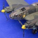
Thanks Peter! Making progress on the intakes. Much sanding, followed by putty, followed by more sanding. In the end, they came out "ok" and save me a decent amount of $, so it was worth it. After completion, I painted the interior of the intakes a mix of flat white with a bit of Radome Tan and some grey. Wanted to stay away from the shiny white look. I'm still not done, going to add some localized staining and see how some grey pastels look. Speaking of painting the interiors, these early F-4's had a non-spec application of camouflage paint inside the intakes. The standard called for the first three feet of the interior to be painted the matching camo color to what was on the outside. However, these early jets only had approximately the first 6 inches or so painted. On later jets, almost the entire vari-ramp was camouflaged. Forgot to mention in my last update but on these ramps, the section aft is covered with indentations, representing rivets. On the real thing, these rivets are nearly invisible, so I applied a skim coat of putty and sanding the surface smooth. Here's a nice example of the early intake paintwork. Also note the bizarre looking external tank and its pylon. Aside from that, this is actually one of better paint jobs on Wolfpack F-4C's during this time frame. Here are my vari-ramps, still need to add some weathering and put a wash on the hinge areas. Inside... The intake with the ramp dry-fitted. Still need to add the pitot tubes. Hard to get a decent picture but it looks pretty good IMHO. While I was at it, I painted the area of the fuselage that would be covered by the ramps. It would be pretty hard to paint this area once the intakes are glued in place. That's it for now, thanks for checking in.11 points -
For those of you who haven't caught up with the news, we now have this available: https://www.klp.com.au/product/building-the-revell-me-262b-1-u1-nachtjager-in-1-32-scale/ Kev9 points
-
Thanks Nick and Rainer, I also couldn't wait to see what lay under the masks. I'm happy to report that Nick cuts great vinyl - no paint bleed under his masks. We'll see that in a moment, but first a little bit about the decals. I used the 2 Squadron badges from the AIMS Decals 'Korean War Mustangs' set, since they are the only ones I know about in 1:32 scale. This is how they look straight off the sheet - not bad, but could be improved a bit. Here is the real McCoy. Notice the number 2 is in black, and the feathers in the wing are actually pale blue. I took the finest brush I could, and painted the 2 black, and the feathers in blue. The writing in the scroll should read SURSUM PRORSUSQUE, But my hand just isn't steady enough... The carrier film is just one of those things I'll have to live with - decals on a metal finish are seldom perfect. The overall effect of the decals is convincing though, and a Korea Sabre wouldn't look the part without all the stencilling! Look at how neat Nick's reverse masked M looks. A large M goes on the underside, and here it was quite feasible to use the mask more conventionally. In case you're wondering, that is a very old 1:48th Hasegawa Sabre in the background. I couldn't help smiling at the original kits decals. Just goes to show how far the hobby has come since the 1970's! On the verge of assembling all the loose painted parts now. Till then, Cheers! Sean8 points
-

1/24 Airfix F6F-5 Hellcat "Kicked Up A Notch": New eBook Now Available!
dodgem37 and 7 others reacted to chuck540z3 for a topic
Thanks Nigel for your kind offer. Yes the central core is way oversized and a bit oval, but with lots of sanding I was able to make it workable as shown below. December 4/21 With the landing gear mostly sorted out, I decided to get to the highlight of this kit, which is a very detailed Pratt and Whitney R2800 Double Wasp Engine, which was used in many other aircraft including the Corsair. Like all aircraft engines there are several variants, so exact details can change slightly from engine to engine, so I’m going to pick and choose how I detail this engine with what I like, rather than worry too much about accuracy. Almost all of the engine parts are on Sprue J and fortunately, none of them are short shot like the Sprue F in my kit! I finally got my replacement parts from Airfix in the mail after waiting for 3 weeks, which is sort of normal these days for deliveries from Europe. All of these engine parts have a noticeable seam lines on them that needs to be removed, which takes a lot of work and patience, but the quality and detail of the parts is really well done. Here’s a pic of the parts needed for Steps 150-158. The assembly of the main engine parts is an engineering marvel, but like most of this build, the fit of all of them is way too tight. This is especially true of the ring on the right, Part J6, which needs a lot of sanding in the interior before you can even begin to fit it over the tubular assembly of Parts J3 and J4 on the left, which also needs to be sanded down quite a bit to allow clearance for all of the other parts, like the push-rods on the top. Note the notch in all of the parts that fit into the groove of the central tube, which ensure proper alignment of this complex assembly. As shown at the beginning of this build, I’m going to be using ANYZ upgrade parts and braided line, but there are no specific instructions on how all this should be used, so I’m just going to wing it. The ANYZ spark plugs come in a straight version and also one with a curved lead, which is perfect for the front cylinders as you will see below. To get them to fit, the small holes in the cylinders were drilled out to size. A close-up pic, showing the kit and ANYZ detail. Only the front cylinders should have the curved spark plug leads, since most of the rest of the plug wires need to be placed through shrouds that protect and hold the wires. The cylinders on the left are the front of the rear bank, showing the straight plugs. The rear view of both banks with all straight plugs, which show the holes for exhaust manifolds that will be added later. Here are the main engine parts dry fit together. The fit is tight enough that no glue will be required for anything other than the front cone and electrical conduit horseshoe. While the push-rods generally touch the cylinder heads where they should, some have a bit of a gap. The solution is to paint everything first, assemble, then close the gaps with CA glue and touch-up the paint with a brush. While the cylinder heads should have a distinct seam line in the middle, the oval assembly on either side of the cylinder (valve covers?) do not. The fit of these parts is a bit crude, so they should be sanded down smooth and the seam line filled, which I’ve done with clear CA glue, which still shows the gap. Although hard to see, I also punched three fasteners into the top of each cover. The spark plug wire shrouds need to be opened up a bit to allow the ANYZ braided line to thread through. The kit instructions in Step 159 and 160 show the location of where the plug wires and other wiring should be located, which at first looks very complicated and intimidating. Once you realize that every cylinder has two spark plugs with wiring that goes into the wiring harness side by side, the light bulb turns on in your head and everything is really quite simple. Using the same color scheme as the instructions, this is generally how the wiring should be located, with the Purple/Red pairs for the front cylinder and the Green/Yellow pairs for the rear. Note the size differences of each wire, to accommodate short or longer routing of each wire. There are a few more wires underneath, but they are quite simple to locate as well. Looking at the ANYZ assembled engine pics, the wiring harness connectors have been cut off and replaced with ANYZ resin replacements. While this looks attractive, this wiring is going to be fragile enough, so I’m going to stick with the hollowed-out kit wiring connectors that will provide a solid base to glue the wires within. Sometimes function trumps form.... The next step is to paint all of the engine parts and then re-assemble the engine, but before I do that, I will add the plug wires to the front of the rear cylinder bank (yellow wires) for ease of access, while the remaining wiring should be easy enough to do with all the parts in place. Closing thoughts and advice: - The biggest challenge of this engine isn’t the complexity, but all the seam lines and flash that needs to be removed from every single part - The fit of most of the parts on the central cylinder (J3/J4) is ridiculously tight or impossible as noted by Nigel above, so you need to do a lot of sanding to get the parts to fit properly - The quality of the parts and detail is terrific, and - The engineering of the engine is really well done, other than tight fit - Finishing this engine is going to be a lot of fun. That’s it for now everyone. Thanks for your continued interest in this build. Cheers, Chuck8 points -

Fw 190A-5 Walter Nowotny Stab I./JG 54, Orel 1943
ARay87 and 6 others reacted to Miloslav1956 for a topic
Project 26. 1/32 Hasegawa kit, Eduard cockpit & Look, Barracuda wheels, painting mask homemade, all colours MRP, HGW rivet set7 points -
Fw 190D-9 Brown "4" W.Nr.500647.
Nikola Topalov and 6 others reacted to Miloslav1956 for a topic
1/32 Revell model, Yahu instrument panel, Barracuda wheels, Eagle cals, painting mask home made, riveting home made All colours MRP7 points -

Trumpeter 1/32 EE Lightning, ****Finished****
Anthony in NZ and 6 others reacted to Robthepom for a topic
Bit of an update, halves are fitted and wings, good fits just a smidge of filler. I need to tidy the seams a bit more and continue to rivet, i should have bought a tool. I'm enjoying the kit I just wish it had the correct belly shape. Kit is much like myself, large with oversize belly. I'm very impressed with the surface detail, cant wait to get some paint down. The exhausts are masked off with Sodastream gas caps which were perfect fit. stuck with white glue7 points -
The guys are neatly packed within the cockpit. The wings and T tail were just 7 parts. And now the canopy has been taped and the white primer applied. Next will be subtly highlighting some panel lines and then gloss white paint.7 points
-

Another Hasegawa T bolt Bubbletop, my first LSP. November 12, 2022, It is DONE at last!!!!!!!!
Greg W and 5 others reacted to Citadelgrad for a topic
I finally got a chance during the time filled with hanging lights, shopping, parties, and socializing, to start the finishing touches. not a huge step, but when this is finished i will unmask and attach the wondscreen, so that is a big step for me. i ordered up a backup gunsight, and it is the finest, most delicate piece of PE i have successfully worked with to date. I almost destroyed it getting ready to remove it from the tiny fret, pressing down with my fat fingertip warped it a bit but i coaxed it back into shape. then i made the simple 90 bend and decided to paint it before installing. By grabbing the short end of that 90 with my squeeze to open tweezers, i was able to paint everything but the part that gets glued. the crosshairs and circle are so fine that even with thinned Vallejo paint and my finest brush, every stroke filled in the circle. I soon learned that a quick blast of breath would clear it. i decided to let it really dry before proceeding. This thing is so delicate i think a post install coat of paint might warp it. A picture with the main wheel for scale question: there is a very fine turned brass rod that represents the front sight part that goes in front of the windscreen. Its hella fine. Should i try to drill a hole for it? Surface mount? Glue? Help? thanks much for looking.6 points -
Fw 190D-11 Red "4" , Leutnant Karl-Heinz Hofmann, JV44
Nikola Topalov and 4 others reacted to Miloslav1956 for a topic
1/32 Hasegawa model, Real Model Conversion set, Eagle cals, HGW rivet se & wet transfers, Barracuda wheels, painting mask home made, All colours MRP.5 points -
.thumb.jpg.f0920d798d5d8600fb58b1d8a906ddff.jpg)
Tamiya F-4E | Phantom | from Nam 1:32
Geoff Staniland and 4 others reacted to shadowmare for a topic
Overall good kit, but not from "finest" Tamiya models shelf. Intakes are unfortunately totally wrong. Used addons: - resin exhausts - Aires intake plugs - Eduard photoetch inside cockpit / plackards5 points -
I went along to this event yesterday: a small but beautifully formed show held within the Midlands Aviation Museum next to Coventry airport. There weren't many club stands, and not many LSPs on those that were there, but this Hawk really caught my eye: what a superb finish! Wish I'd got more photos now. (I don't think RFI is appropriate, as it certainly isn't mine - wish I could say it was!)5 points
-
Thanks so much for the FB tip. Funny, I was just thinking about checking out FB for some groups that might have good 8th TFW / Vietnam Era pics. FB (as much as generally it sucks) is a fantastic resource. One other passion of mine is Army helicopters. I'm on several private groups dedicated to Vietnam era pilots and also one for the 160th SOAR. I've found some truly amazing pictures and info. I'll head over there. Before I do, a quick update - as mentioned, I was going to weather the intake interiors a bit (also added the pitot tubes that controlled the vari-ramps. I'm a big fan of pastels, this took 2 minutes with some ground up dark grey. Pitots were dark grey with a pencil run around the probe itself to give it a metallic sheen. Still will add a small bit of chipping here and there but I think I'm calling these pretty much done.5 points
-
My pleasure. It's a while since I did mine, but here's my tip for nose weight, using the stick-backed ballast that our flying model brethren use. Chop the bottoms (the non-visible) parts off the oxygen bottles and pop it in there.5 points
-
Aires F-14B Tomcat cockpit before it goes into the Tamiya fuselage: A pleasure to work with, I just added switches lever.5 points
-

HK Models 1/32 B-17E/F WIP
Rockie Yarwood and 4 others reacted to Gil Hodges for a topic
The last 4 figures have been reposed and positioned! The 2 waist gunners, for which I used standing "top turret" figures needed considerable altering of the legs since the floors are uneven, as well as an arm reposed to help support themselves. The rearmost figure was also slightly bent at the waist to make him a bit stooped and fit in the lower ceiling farther back. The radio man and the other crew member were used almost as is. The 2 standing figures are held in place with the help of a bit of wire in the shoe bottom that anchors them to the floor. So.....next week I'll start priming them and cleaning them up to get ready to paint! Pics of the crew when they're done will be next! GIL5 points -
I'm beginning to think JetMads may be the closest I'll ever come to seeing an XP-67 in LSP form I still doubt even they will do it, but they seem to be getting a bit more esoteric with their releases, so anything s possible.5 points
-

RAF FG.1 XV571 WILD HARE Phantom Conversion
Scotsman and 4 others reacted to Anthony in NZ for a topic
So, where are we now....... Finished up filling the holes for the outer pylons to reposition them into their correct position. Lower intakes needed some work moving panel lines, changing shapes, removing access doors and moving fastener positions around to match the Spey differences. The recess inserts for the catapult hooks were glued in, note they are a different 'corrected' shape now (not the recess, itself but the panel around it). Here you can (hopefully) see the completely different lower profile of the Spey belly. The WH part was unfortunately different shapes L & R and the Sparrow/Skyflash recesses were misshapen and wrong. I really would have been better off modifying the kit again. Never mind, I have done it now.... I am probably not going to add detail into the missile recesses as I will have 'Drill Rounds' fitted and wont be seen. Here you can see where a lot of the time has gone in reworking the belly and the surface details added. Close up This is just my first coat of Mr Surfacer to see where I am at. Pretty happy with the results. I am really wanting to add all these details to the belly as it will really make a difference for weathering. Right-O back to more surface details, wont be long before I get the big reinforcing 'straps/ Doublers on the lower spar cap etc. Massive thanks to @Gene K for doing such an awesome job studying all of these variations and getting them as accurate as possible and making them available as a downloadable file to cut on your Silhouette cutter, hopefully soon. Anyhoo...back to it Thanks for stopping by Cheers Anthony5 points -
Disclaimer - this is going to be a very long project. I've got other irons in the fire and limited modeling time. This is just my introduction to the upcoming build. Of course I'll be using the Tamiya 32nd F-4C/D kit, along with a (surprisingly) large amount of aftermarket bits. First off - my subject. I have never much interest in the Phantom from a modeling standpoint and zero interest in the F-4C version. The C just seemed "dull" compared to the colorful Navy jets and the later, more sophisticated Airforce D and E models. That changed when I happened to take a look at Fundekals downloadable instructions for their latest release - F-4C MiG Hunters - Operation Bolo and Beyond. As with all of their decals, the instructions are absolutely amazing. They really qualify as a reference booklet, much more than just "Apply decal X here" that most aftermarket outfits provide. I highly recommend you grab a cup of coffee or your favorite adult beverage and give them a read. They can be found here: https://www.hobbyzone.biz/fundekals/docs/fun_32011.pdf Once I read through the instructions, I became fascinated with these jets. Aside from their history (and that of the 8th TFW "Wolfpack" and their legendary wing commander, Col. Robin Olds), what really blew me away was the absolutely insane variations in markings, paint jobs and weathering on these Phantoms. From a modelling standpoint, I am drawn towards unusual, non-standard subjects. The majority of the jets in the Fundekals set were early F-4C's, which started life in the USN standard light gull grey over gloss white. Once losses started to mount in SEA, there was a crash program to camouflage all tactical jets in the now famous SEA scheme. These early jets were mostly painted at repair depots in the Philippines. These early paint jobs weren't exactly per the USAF specification. The gloss white undersides, with all the Navy stenciling, were left alone (the AF spec requires FS36622 camouflage grey undersides). On many of these jets, the existing large underwing national insignia and "USAF" were just lightly sprayed over with white, allowing them to still be faintly seen. The topsides were done roughly in accordance to the prescribed pattern but it seems that no two jets were painted exactly the same. The paints used also seemed to weather quite severely in the tropical conditions of SEA. Lastly, the jets changed markings quite frequently and the old markings were painted over using whatever paint was available. Often a dark olive brown was used. These non-standard paints were also used for touching up the rapidly fading tan/dark green/medium green paint job. Some of the bright yellow rescue markings were also lightly overpainted to tone them down, while many of the large tail codes were done in some unknown shade of light grey, presumably for the same reason. Here are a few examples of some interesting paintjobs: Between all three jets, we've got "50 shades of tan": Worst looking F-4 ever: SEA scheme with a gull grey canopy frame and gloss white AC intake. In addition to those "features", we have probably a dozen shades of paint (some just randomly applied), grey and white squadron codes and toned-down (overpainted) yellow rescue markings. Puts late war Luftwaffe aircraft to shame! So to wrap up this longwinded intro, here is what I'm tentatively planning to replicate (profile taken from the Fundekals instructions): More about 589 in my next post. Thanks for looking!4 points
-
Fw 190A-7 Heinz Bär
TenSeven and 3 others reacted to Miloslav1956 for a topic
1/32 Hasegawa kit, Eduard cockpit & Look, Barracuda wheels, Eagle Strike decals, painting mask homemade, all colours MRP, HGW rivet set4 points -
Hi guys, its been a few months since I posted anything. In mid-August I got broadsided by a person who ran a stop sign. I suffered several broken bones and lots of cuts and gashes, but nothing life threatning fortunately. I has taken some time to heal up and it has only been the last few days that I have been able to get back to the bench. The first order of business is to finish this project which is coming down to the final phases. The photos are pretty basic but show the base paint job on the exterior, as well as, the support dolly. It is good to be back! Ernest4 points
-
Panel fit is excellent. Buttoned up build is best option (IMHO)4 points
-

EA-6B Prowler (02 April: Done!)
stusbke and 3 others reacted to easixpedro for a topic
Have no fear! I kind of have ADHD when it comes to concentrating on these longer builds. To the point that I actually spent last night making some ALQ-99 pods. Didn't feel like attempting to pull another canopy at the moment, so smash formed a couple of pods. Hopefully some pics here in the next few days--my hairbrained, ill-though out plans just might work, as the pods look quite good! -Peter4 points -
Hopefully they'll work their way up to the Grumman Panther/Cougar too as well now the FMP kits are gone.4 points
-
Wolfpack Phantom - 8th TFW F-4C
Paul in Napier and 3 others reacted to John1 for a topic
So, onto the intakes. As been mentioned in pretty much every build posted here on LSP, the intake trunks don't come close to fitting properly. No idea how T could have screwed this up. So, your options are - add intake covers, drop $35 or so for aftermarket intake trunks or fix the problem. Thanks to a bunch of good info posted here, I decided to take a shot at option 3. First off - cut out the intake trunks that are attached to the fuselage. Easy so far (except for the gouge that I put in my finger when the Xacto blade slipped). The end result is that you will glue this part onto the kit's intake trunk assembly and then glue the entire assembly into the outer intake housing. Here's a rough mockup of what it will look like. I've taped the cut-out fuselage intake to the top of the trunk assembly. Here's what it will look like when you are done. At this stage, the intake assembly pretty much just snaps into place. Only issue is that you have a very pronounced step between the inlet of the truck (as seen above) and the interior of the intake housing. This is where you have to do a bit of work. I guess in theory you could simply putty the crap out of the step to fair it in but all that putty may not set up very well and could shrink later on. Best option is to add thin strips of plastic card (I used .005" /.13mm Evergreen styrene). Here is what it looks like. I have to admit, this is some of the worst work I've ever done. I think my Labrador Retriever could have done cleaner work. But you know what? Once you add some putty and sand it down, it's going to look fantastic. Keep in mind - no one will ever see your work from this perspective. When you look into the assembled intake from the front, even in this condition, it looks pretty decent. After the final touches, it should look fantastic. So that's where I'm currently at. I've already applied the putty and after smoothing it in with my fingertip, it's looking good. A quick sanding, some primer, and then the final coat. A note on colors - I'm struggling with the correct color for the intake trunks. It's definitely not gloss white like you see in most models. At this point, I'm going with flat white with some radome tan added. I may use some grey pastels for the final touch. Lastly, I need to add a band of the upper camouflage color to the front of the inlet. I think there was some discussion on how thick this band was but I can't seem to find it. If anyone has some info, please let me know. I believe those early F-4C's had a lot of non-standard paintwork, including this area. Thanks for looking in!4 points -
Wolfpack Phantom - 8th TFW F-4C
Paul in Napier and 3 others reacted to John1 for a topic
I'm back... Finally completed my P-47D so it's time to get serious about this build. Before I show any progress, a warning - this build (I suppose like all of mine) will be a very slow project. If things get too hairy, I've a KH Blackhawk with a ton of aftermarket stuff calling me to turn her into an OIF UH-60L. Let's keep our fingers crossed that I can stay focused. First off - the obligatory box shots. The box: Yep, the same one you guys have seen for the last decade or so. Nothing special except it's pretty damned big! Shot #2 - the aftermarket stuff. It's a horrible picture. So I'll detail what I've got so far are: Eduard F-4C/D exterior details. GT Resin Exhaust cans AIMS Martin Baker Mk 5 Ejection Seats GT Resin ALQ-71 ECM pod Fundekals Wolfpack Set I'll go into details on all of these as I start to use them. Sharp eyed readers may note the lack of any upgrades to the cockpit aside from the early version bang-seats. That's because I'm still waiting for Quinta to get off their butts and release the F-4C cockpit set they've been promising for ages. So far they have done the J and E. Hopefully they get the C out before I start the cockpit. Otherwise, I'll go with the Red Fox set. The RF set is very nice but the Quinta ones appear to be just a bit sharper in details and they also provide the cockpit side wall details such as the prominent circuit breakers and also smaller other bits that RF did not. First order of business should have never have been required. For some reason Tamiya must have used their B Team to research and design this kit. They apparently used only a single Phantom as their reference and they one they chose was previously used for ground crews to practice battle damage repairs. The fuselage is covered with raised patches that need to be removed. Here is a very illustrative picture from another build that shows how bad it is. It took me quite a while to sand and then rescribe/re-rivet all the surface detail that was lost. A major pain in the ass. I've hit the fuselage with some Flory wash just to check the work. I've got multiple areas that need additional cleanups, so this is very much a work in process. Sorry guys, I didn't realize how horrid these pictures were until I saw them posted here. I'll go back and take some detail shots when the lighting is a bit better. Anyway, that's gonna be it for tonight. Next up will be correcting the intakes. Until then....4 points -
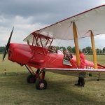
Hey all, This is something right out of left field for me, my first ever motorbike model, ..I have always liked the look of Tamiya's Motorbike kits when done well, even though I have absolutely no interest in motorbikes at all, so when I needed a bit of a break from my P-47 build that I was doing, I grabbed two kits for a change of subject, a Takom 1/35 Stug lll Ausf G, and this one from Tamiya, ...what a breath of fresh air doing them was! .....and got me out of a bit of a rut I was in. These Tamiya bike kits are brilliant, but I had a couple of issues due to operator error I would say, one of them was attaching the rear view mirrors, ...what an absolute PIA they were, I must have had twenty go's at them before I got them to stick! I also used the Tamiya Fork upgrade set, these are just gorgeous! Anyway, I enjoyed this build, and have learnt some things for my next one... The Panigale decal is missing from this side because I had an accident with the fairing after it was finished, and had to repaint it, and I didnt have another decal to replace it. Thanks for looking, Jeff.3 points
-
1/32 FH-1 Phantom from JetMads !!!3 points
-
Another 1/32 release I've been waiting eagerly: 1/32 X-3...3 points
-

SAAB J-29F/B from Fly model
Rick Griewski and 2 others reacted to Kagemusha for a topic
Following on from the sprue shot of the wings three years ago... A photo of some other stuff - a technical term.3 points -
I didn't quite have the same luck that the other fellas had with this kit: It turned out OK in the end, though: I'd actually consider building another one, I but I do have a Special Hobby example in the stash to get to first. I'm hopeful that someone will eventually re-introduce the Kitty Hawk kit into the market. Kev3 points
-

1/32 Revell Me 262B-1/U1 Nachtjager
scvrobeson and 2 others reacted to Thunnus for a topic
Thanks Kevin! Happy and honored for the opportunity to present this build in e-book format! I hope that my guide is useful to modelers building this very nice kit from Revell!3 points -
We sure did. There was a dayglo cross on the right hand side of the front undercarriage door for quick harmonisation of the gun.3 points
-
I use Microscale Liquid Decal Film. - Brush a (not so) thin coat on the decal with a flat, soft brush. - Wait 10 minutes. - Repeat. - 30 minutes after the second coat, your decal is ready. - Apply as usual. HTH, Quang3 points
-
OK, on to next steps, which shows the progress after quite some hours of modelling.... VERTICAL TAIL This needs corrections as well with an increase vertical tail height at the lower base by 3 mm and at fin top by about 2 mm (total increment = 5 mm); With a razor saw, several cuts were thus made. For the increased height, a few strips of card were used. The upper tail section will be a piece of card 2 mm. It was decided not to change the vertical tail fairings, though not 100% accurate but good enough. These root base of 2 x 1,5 mm thick = 3 mm card sections were set on the rear fuselage. The rudder will also be enlarged with card. (note that the raised knobs were sanded off later on). MAIN ASSEMBLY An important step is now to join the forward and rear fuselage-wing assembly. It was crucial to check symmetry and get enough strength with long strips of thick sprue. An exciting moment! (prepared vertical tail is also seen) As seen, the air funnel inside and extra stips will be set between forward section with spine and rear spine. Let dry for at least 24 hours. MAIN GEAR BAYS Back to the landing gear as noted earlier. For the corrected main bay opening shapes, a piece of curved card insert was made to fit. This way, the main closed doors will be “virtually” lengthened 10 mm. Also bits of card were needed to get more strength and all set with clamps to dry. Making this curved card insert took quite some time. Note that the main closed doors are part of this insert. Putty will be needed and card will be used at the upper spine…. A check was made with the drawing and it look OK. The spine insert here is 17 mm in 1/32. IMPORTANT CHECK A check was done and now a 1/32 Gripen model is progressing that is far more accurate in shape : (1) increased fuselage lengths of 4+17 = 21 mm. (2) with corrected wing span 2x 5 mm at the rear and the leading edge sweep looks much better now. Note: at the ailerons, the trailing edge sweep (about 1 degree) is not entirely accurate but it was decided not to mess with the thin trailing edges here. Now a lot of putty and sanding is needed... several passes are needed..... (photo here shows still the uncorrected gun fairing location) Each intake upper corner near the canard station should be a bit more curved. Sanding was done, be careful here as the plastic is thin. I had to make some repairs at the intake corner insides here as the plastic was very thin. A small fairing was added from strip. The better result is seen here… The spine exhaust aft of the cockpit took some work to get a perfect symmetrical result. Some small amounts of putty and sanding still needed... GUN FAIRING I found a bit too late that the lower gun fairing needs to be lengthened in the middle by about 12 mm and relocated as well. So the kit shape was cut off horizontally with a razor saw. ... this is risky! It can be done. Some card was set. A 12 mm section was set in the middle and putty and sanding needed again! INBOARD FLAPS The inboard flaps are still separate parts. They will also be used to suggest a slightly better trailing edge angle as I had to rotate a bit the wing planform. Measuring and dry fitting was done now. The gaps between flap and fuselage will be kept but not too wide with card and putty. Pieces of card (5 mm width again) are needed… and putty! The changed inboard flap also adjusts the trailing edge sweep which looks good now. VERTICAL TAIL The corrected vertical tail was set onto the rear fuselage. Ensure a vertical sit! Putty was needed at the base. A small correction was also needed at the lower base as seen here. The rudder was made heigher / enlarged with card and putty as well. At the wing kink/ leading edge aft of the canard station it was found a small extension was needed as seen on real Gripens. It took quite some time to see this as it is missing in the original kit and is situated at the mid fuselage extension. (see drawing check above). The small extensions were made with a bit from the spares box, putty and sanding. Here the overall result is seen of the corrections till now. The model still needs some small putty clean ups and than a first grey base primer. Than a photo check will be made with the camera. ..... to be continued....3 points
-

1/24 Airfix F6F-5 Hellcat "Kicked Up A Notch": New eBook Now Available!
Landrotten Highlander and 2 others reacted to petrov27 for a topic
looking great and very interested in your engine detailing. I am working on the same engine myself currently with the AnyZ set and yes as you noted the braided lines can be challenging to work with. In my trial and error over the weekend one thing I found was that you can insert a bit of fine lead wire through the braided line and just put a tiny bit of glue on the ends to keep the braid together and not discolor the entire line. The lead wire inside made it hold a certain "bend" better - I may go that way on mine though not sure yet if its worth the extra work....3 points -
JetMads 1/32 FH-1 Phantom
LSP_K2 and 2 others reacted to thierry laurent for a topic
Surprised they have chosen the Phantom rather than the Banshee...?3 points -

1/24 Airfix F6F-5 Hellcat "Kicked Up A Notch": New eBook Now Available!
SwissFighters and 2 others reacted to Fanes for a topic
Brian had a fantastic solution for glueing the braided lines: Cheers Joachim3 points -
Make the others jealous
scvrobeson and 2 others reacted to Robthepom for a topic
something a little different3 points -
I considered doing a Moonbat myself but trying to get all those fillets blending together correctly in CAD so that the design doesn’t end up looking like a Picasso would be very tricky3 points
-
1/18 Scale Blue Box F4U-1A Corsair Modification
daHeld and 2 others reacted to Pete Fleischmann for a topic
Hi Jay. yes. It’s worth it. Amazing and inspiring work. And as such, I suspect there was a little modeling jealousy in play with that unknown modelers comments. Thanks for this- it’s amazing. best Pete3 points -

Dornier D0-335A-12, by Zoukei Mura - Finished
Bruce_Crosby and 2 others reacted to Dpgsbody55 for a topic
I think this kit dates from a time when Z-M molded all exterior pieces in clear so that you could show off the insides to full effect, or paint one side and leave the other clear, or just paint the lot. If I recall correctly, their TA-152's were the same. Someone please let me know if I'm wrong on this. Either way, it's part of the Z-M philosophy of modelling the entire plane and not just the obvious bits, as they like to show the workings. Personally, I like this way of doing things. This authentic look was also a feature of the Z-M Henschel HS-129 I built a while back. Same style of instructions, which are as detailed as the model itself. They also give the modeller pictures of how each stage should look after you complete those stages, which is a great help and another nice feature of these kits. Thanks for joining me on this journey. It's all just a part of how Z-M do things, but it does have a purpose in holding the heads onto the block and aligning them properly. Glue is only applied to the outer edge of each head, and the con rods interconnect so you glue that connection too which gives the assembly a better bond. Tamiya do it a little differently, but both give you a better result than most others who offer an engine in their kit as the parts have a more detailed look. Yes, I like HKM's offering a weight in their kits. Their Gloster Meteor has the same feature and I do wish Z-M had thought of a way to install a weight. I'll be using Liquid Gravity on mine, but it would be nice not to have to spend more money mail ordering stuff..... Which the postal pixies STILL have in their clutches... They're late on their promised delivery date too... But perhaps the way Z-M have done it here, I'll end up with a better model anyway with Z-M detail and a nose sitter. Time, and whatever skills I can bring to bear, will tell on that, though. However, it must be said that many other kit manufacturers also don't provide a nose weight for their tricycle undercarriage'd models either. I'd agree that more should. __________________________________________________________________________________________________________________________________________ So after the last installment I'd started work on the rear engine. The next stage was to add the kit's spark plug wires and some of the plumbing. Here's the outer ignition harness, magneto and supercharger in place. All this was sprayed with Tamiya rattle can AS12, then some details picked out, and the flexible plug leads were painted a slightly darker metallic gray. The flash on my camera has caused a blurring of the silver colours against the black engine. It's not actually like that "in the plastic". Here's the other twelve plug leads. As I mentioned in my earlier update, I'd already put the fuel injection distributor and inlet manifold on before I gave any thought to the lower ignition harness, which meant I couldn't clean out the plug holes to firmly glue the parts in place. So I cleaned out what I could then glued what I could. The remaining unattached leads were glued in place with some Tamiya super thin glue. This seems to have worked as after all the handing during building this motor, they're still in place. If I get really ambitious with the front motor, I might make the fuel lines. Or not, if I regain my sanity.... In the next pictures, the exhausts have been added, along with some of the engines cooling system. The header tanks are interconnected and the pipe leading out of the bottom of the tank connects with the same tank on the other side, and also with a pipe yet to the added to the underside of the engine. The exhausts, however, go on first and the header tanks glue to the exhaust shields. As the plane I'm building was very new when the war ended, I'm building it with little wear, so the exhausts themselves were painted steel, then aged slightly with a dry brush of rust. Also, note the orientation of the exhausts - they're facing towards the front of the engine. Here we have the engine finished. First, the front engine mount goes on around the reduction gear housing, then the mounts to the mounting frame. Then the rear engine mounts go on and the whole lot is placed in that frame. The last bits to go on are the pumps in front of the header tanks on each side, which connect to one pipe underneath the engine. Then a third pipe is attached underneath the engine. I assume that these will connect with the radiator at a later stage. Here's some shots from each angle. Right side. Left side. Rear. Front. Underneath. Lastly, placed into the front bulkhead and into the fuselage, so that I can work out what part of the fuselage will need painting RLM02. Did I mention that the postal pixies still have my two week old order of Liquid Gravity????? I know I ordered from Melbourne, 3,420km away from my home on the other side of the country, so I'm guessing said pixies have placed it in a little red wagon and are walking it across the country. . This means I can't finish the front cockpit area. So I think I'll do a bit more on the middle cockpit and maybe the bits behind the rear engine. I guess all these sub assemblies have got to be done anyway, before I can glue the fuselage halves together. On the bright side, it may help me get a better handle on just how much weight I need to add to the nose when I finally get my parcel. You may have noticed in earlier pictures how I've crossed out those instructions that I have completed, which may help me figure out this enforced haphazard construction plan of mine. Until next time. Cheers, Michael3 points -
Short Sunderland MkII
Sharkmouth and 2 others reacted to tomprobert for a topic
Howdy all, I've concentrating my recent efforts on the beaching gear for the big Sunderland - I was for a while considering a water diorama but then it occurred to me that I don't have a 5ft by 5ft display area so wheels it is. I love the challenges kits of this nature bring and the research that needs to be done as it always throws up so much information about a particular aircraft. It looks as if there were three distinct types of beaching gear, all with their subtle differences, and that does not include all of the different float, wheel and tyre combinations. The version I photographed at Solent Sky looks to be either very late or post-war, therefore not suitable for an earlier MkII of around 1941 vintage. It seems they were painted differently too - some left in natural metal and others in anti-rust red. Strength is a must on such a large model, and I did consider using a brass core but my soldering skills are not up to the job. Instead, I raised my stash of spare sprue and found some really chunky parts from the HK B-17 kit and used these as a starting point to form the core of the beaching gear. I used a perpendicular junction point as this provided a very strong 90-degree angle for the main strut and axle without having to worry about the joint failing at any time: Over a few sessions I then built up the external structure with plastic card, Evergreen and more sprue and detailed them according to references: The rear beaching gear is a more complex affair and is a sturdy box-like structure with a cradle for the rear of the hull to rest in: Here are the main components ready for a trip to the spray booth: I've decided to go for anti-rust red as it'll add a splash of colour. After the base-coat they have received a light wash and some rust streaks etc - the real things got terribly battered so I may add some more at a later stage: These then slot snugly on to the forward fuselage: And under the rear of the hull: You'll notice a distinct absence of wheels at this stage - a friend is kindly helping me out by designing and printing me a set that will be added in due course. Here's an early screen shot of how they'll look: And now here we are: sitting proudly on it's own three legs and waiting for the next stage of detailing. For some reason, my cat never looks impressed with my models - she must get that from the wife! Until next time, Tom3 points -
Saving a Canso
Anthony in NZ and one other reacted to LSP_Ron for a topic
Having touched this airframe as an enthusiast multiple times over the years. I found this very interesting.2 points -
Hi all, my first entry here is an ICM I-16 type 24 with eduard PE parts. It was my first step into large scale WW2 modelling, so I thought this would fit as a first entry. Those corn plants took me longer than the whole plane. Meanwhile I know that this very plane never was flown by a female pilot, but back then I didn‘t care. It just looked cool… . I hope you like it. best regards, Andreas (Borsos)2 points
-
What do you all listen to while modeling?
Troy Molitor and one other reacted to LSP_Ron for a topic
Pink Floyd2 points -
.thumb.png.84c5d3a464f2dd83f0ac37a5aac81ec8.png)
1/15 Bf109 " my first fully scratch build"
TAG and one other reacted to Antonio Argudo for a topic
Thanks Adam, yes it is a challenging project for me but I'm having fun in this project, thanks for following mate! cheers Some progress from the last days, still figuring out many things as there is no instructions to follow, the most noticeable are the main spars and some more cockpit elements, also using original blueprints printed in scale, hope you like it, cheers2 points -

WNW SE5a
Greg W and one other reacted to europapete for a topic
The top decking and gas tank are just dry fitted for now, still more stuff to add yet. So that's it for today, as always comments suggestions and thrown cabbages always welcome. Regards, Pete in RI2 points -
1/15 Bf109 " my first fully scratch build"
TAG and one other reacted to Antonio Argudo for a topic
some progress update, the nose ribs were glued, also I am thinking about doing 2 interchangeable noses using some aluminum tubing system and some magnets, one closed and a second with open cowling covers and displaying the engine, right now playing around the cockpit dimensions and elements, thanks for watching, cheers Tony2 points