Leaderboard


Popular Content
Showing content with the highest reputation on 07/08/2019 in all areas
-
hello again fellow modellers Hi Jay - it's just a cheap Chinese one, but seems perfectly adequate for my needs - I just need to learn how to use it Ahh - that is one good looking Spit - but having done one, I doubt I will do another (especially as it was my favourite Mark..) They are really useful - thanks Chek, I have lots of resto shots, but very, very few of it actually finished so these are brilliant! ..I have been away much of the week, so just a little more done - but each part is one more step towards completion! ..firstly, the control column was finished & painted - I just need to work out what to make the canvas gaiter from as all the materials I have the weave is over scale.. ..and dry fitted in place.. ..next, the rudder pedals... these are in Lopes Hope... a very obvious feature is the writing on the faces ..this was taken care of by making PE parts - here the rounded shape is being imparted by taping & rolling over some brass rod.. ..soon the base pedals were made.. ..then a kit of parts assembled, including the forks that hold them.. ..I checked and only the bottom of the assembly can be seen, so all the upper gubbins was pretty much ignored.. ..and these were then painted and some light scuffing - washes & weathering will come much later... ..thats it for now.. TTFN Peter11 points
-
I started my adventure with modeling four years ago. And I wanted to show you one of the models from the beginnings of my modeling passion. At the beginning I apologize for the pictures - I know that they are very weak but I did them without studio lighting. The model is the F-8E Crusader Trumpeter 1:32, the model quite easy to build I had small problems were with the air intake. I think that you already know that I always make models straight from the box and try to present heavily exploited machines. Such painting makes for me the models are less "plastic" do not look like toys. Ovcourse it's my opinion.10 points
-
Mil Mi-24 Hind Tiger Meet
Shawn M and 7 others reacted to BloorwestSiR for a topic
The stub wings and tailplanes were next. Once done, these were glued in place. So quite a bit done. A fair bit left too but it's moving closer to completion.8 points -
Mil Mi-24 Hind Tiger Meet
Azgaron and 5 others reacted to BloorwestSiR for a topic
Next up was more masking. Finally, time for the light grey to be applied. Here's all the various masks. I kept them on a sheet of waxed paper in case I needed to do touch ups. Which I was expecting due to the various lumps and bumps.6 points -

Trumpeter 1/32nd F-100D ANG
themongoose and 4 others reacted to crobinsonh for a topic
Here are the final set of shots taken outside on a cloudy day. Glad this one is over - largely my own fault having dropped it and that fact that Trumpeter and the UK distributor off now spares parts service whatsoever (I tried several times with both and received no response). The kit had the very extensive Eduard series of sets, Aires cockpit, exhaust and wheel bays, Avionix cockpit etc There are a number of mistakes - small tanks, early exhaust when it should be the later one. I am sure there are a bunch more. I also noticed post photographing that I have knocked the fuse extenders so that are not all equally spread. I was pleased with the effect of reducing the pin cushion divots that Trumpeter wanted to pass as rivets.5 points -
So, with the help of Peter of AirScale I acquired some clear F-104 IP cards, custom made by a gent Peter deals with. Amazing! I could not have done this part without him, so cheers to Peter! . Its basically a clear sheet of acetate with the 104 instruments printed on it, including many MANY extras in case for when I screw one or more up. You can see the clear sheet here with the Eduard panel taped on top of it. Near perfect fit! An impromptu session in front of a light gives a very general idea of how things will go, but in this case it looks a bit more washed out than it will with the smaller and less intense light behind it: A bit mis-aligned in my haste, but you get the general idea. It will be much more realistic looking with a less harsh light, and not having the halo I light around the outside of the IP either.:5 points
-
1/48th Boeing B-52H Stratofortress
Gazzas and 4 others reacted to tomprobert for a topic
The school holidays are upon us now so the BUFF has been seeing a little action... I've not been happy with the rear turret set up, and I feel the kit's parts don't accurately resemble the real aircraft. Please excuse the terrible photo here (quick snap with the phone camera that I didn't realise was so out of focus) but as you can see... IMG_1127 by Thomas Probert, on Flickr ... it's not even close to the real deal... Tail Turret by Thomas Probert, on Flickr (Used for illustrative purposes only) So, it was out with the hacksaw, and I removed the kit-supplied turret and began by building up the basic underlying structure with some scrap plastic card and some brass tubing for the gun housing: IMG_1135 by Thomas Probert, on Flickr This was then all blended with filler, and sanded to shape. I then added the radar domes from some scrap 500lb bomb noses as the kit parts were too small: DSC_0172 by Thomas Probert, on Flickr Pretty happy with that - we'll see what it looks like under some primer in due course. As I explained in my earlier update, the kit panel lines are rather inconsistent and they've all been filled and an initial coat of primer applied. I've now begun to scribe my own panel detail onto the model - here's the nose: DSC_0179 by Thomas Probert, on Flickr DSC_0160 by Thomas Probert, on Flickr Undersides: DSC_0168 by Thomas Probert, on Flickr DSC_0177 by Thomas Probert, on Flickr The mid-section join has disappeared which is a bonus: DSC_0181 by Thomas Probert, on Flickr I've begun working on the spoilers - vanes still to be added: DSC_0174 by Thomas Probert, on Flickr She's looking a bit of a mess at the moment, but I can assure to that progress is being made: DSC_0158 by Thomas Probert, on Flickr Until next time, Tom5 points -
IMHO , the prop should be visible. There is always something visible enough when a prop is turning If you don't place the prop, the viewer often has the feeling that Something is missing. To me no prop and blurred prop are no good enough compromises. That's the Reason why I prefer for the prop to turn whenever it is necessary for my model, most of the time, I put a small motor in there5 points
-
Paint!!! I have applied the gull grey topcoat. I seem to have applied it a little heavier than I wanted because the preshading has all but disappeared. Oh well. I am not going to touch this for a week as I have a terrible habit of leaving fingerprints everywhere. When I do get back to it I will be masking all of the bare metal areas. Later, Dan5 points
-
Mil Mi-24 Hind Tiger Meet
BradG and 4 others reacted to BloorwestSiR for a topic
I made a bunch of progress over the last couple of days. I got the canopy glued onto the fuselage. The fit wasn't perfect so I glued it on sections. Once the back section was dry, I glued the gunner's part. Doing it this way pretty much eliminated the big issues and left a couple small seams that I filled with sprue glue. The benefit was I got a nice secure bond between the canopy and the fuselage and it self leveled as it dried so I didn't have much sanding to do.5 points -

MH 60 Academy SeaHawk. 1/35 scale.
A-10LOADER and 4 others reacted to shark64 for a topic
Hi Matt. Applied primer coat . Will sand smooth, preshade and highlights.5 points -
Some random pics of our wedding and the absolutely STUNNING surroundings we were in........ The wife near the mouth of the lake, with skies so utterly vivid blue it almost looked fake at the time The view outside the courthouse we got our marriage licence in The wife and I right after the ceremony at nature's altar Wife and I at the actual spot we held the ceramony at For some reason I felt the need for a forest version of Captain Morgan On the way home from said ceramony Heading up to the summit of Mt Massive@ 15,000+ Mt Massive Summit Back at the Lake after the ceremony.... The weather was absolutely perfect, as is Colorado every time we visit. Cheers!5 points
-
HI everyone, I've finally joined the fuselage to wings. It's been a bit of a struggle to get the surfaces as clean as I like, but I feel I've got much done. Here's some pics: I've filled the upper fuselage gun troughs, and replaced the hitherto closed radiator flaps with new flaps made of card. With all of the control surfaces at neutral...or closed, I felt this was a change needed to make the model more engaging to the eye. The original radiator flaps had only 8 external and 8 internal flaps represented in the molding. It took me quite a while to find a useful picture because all of the surviving TA-152's and FW 190D's use the Jumo 213 engine whilst the TA-152 utilizes the DB 603 engine. I found some pictures of the radiator arrangement on the Heinkel 219 Uhu which also utilizes the DB 603 engine. After a lot of looking, I finally decided that twelve inner and twelve outer flaps were required. I also just remembered that I need to make 12 pushrods for the flaps... All of the trailing edges needed a bit of work to make acceptably sharp. It actually took up a fair bit of time. Of course, that meant that I lost all of the raised detail on the control surfaces. Never fear... Silhouette Portrait is here: I found a drawing of the FW 190's framework online and imported it into my Silhouette software. After cleaning it up a bit, I cut the masks and used a few thick coats of Tamiya Matte Red to give me back the raised detail. There's a bit of overspray to remove.... I'm going to have to pin the stabilizers, too. I was going to show them dry-fitted, but they looked a bit too droopy that way. Thanks for looking! Gaz4 points
-
The -3 windscreens had a armored glass behind it and appeared to be rounded in front and no upper brace. The -5s had armored glass glass Incorporated in the windscreen and appears flatter on the front with an upper brace The top drawing is a -3 and the middle and bottom are -5 Canopies. However there may difference among productions runs4 points
-
Mil Mi-24 Hind Tiger Meet
Azgaron and 3 others reacted to BloorwestSiR for a topic
Once the canopy was dry and I had sanded the bit of filler down, I masked it off and sprayed a coat of black. This was followed by Gunship Grey. Then I started on applying the paint masks. DN Models make a set of these which is the reason I got the kit.4 points -
I took few shots today, for all of you guys who purchased the Big Lanc. Cheers Martin https://forum.largescalemodeller.com/topic/6774-lancaster-mk-x-fm-159-nanton-alberta/?tab=comments#comment-944503 points
-
Box art http://www.wingnutwings.com/ww/product?productid=3194 http://www.wingnutwings.com/ww/product?productid=31933 points
-
After making sure the clear IP silhouettes fit as they should, it was onto the cockpits themselves. I had previously tested the fit of these in the fuselage separate from each other, but took this opportunity to unite the two cockpits while they were temporarily held in the fuselage, so fit would not be an issue later. I glued the two ejection seat mounts to their respective pit areas, then after careful alignment, glued the two pits together as per the instructions. After that, the two C2 ejection seats slid nicely down the rails into position temporarily. I then mocked up two heads I wasnt going to use for my Master Details pilots, and proceeded to put them in place to see how they fit, and to see if I had any clearance issues with the clear parts. To my surprise, they actually fit really well, and I didn't have any clearance issues, nor did it seam like I was going to have too much trouble customizing hands and arms to match up with the control stick for the pilot either. I took some extra time and using one of Radu's fine saws, I liberated all 5 main glass parts to the F-104 cockpits. Another (good) surprise here, as not only did I not seem to have any clearance issues with the pilots, but all of the glass parts fit really nice, not even requiring finger pressure to line up. All of this, including all 5 canopy parts, radio and rear access hatches are all just loosely sitting on the fuselage here. Even so the fit is evidently good, and should only improve once all parts are exactly where they should be: The radio and rear hatches fit well too, but will just need some very slight pressure on them when gluing to get them in the perfect spot they need to be to allow the canopy parts to all sit there they need to be: All for now gents and gentettes! I've got to go home and make a vid of the lighting setup for Richard, and hopefully will get that fixed as soon as possible so I can move on and finalize the power situation. Cheers!3 points
-

WnW Fokker E.1 (Early)
tucohoward and 2 others reacted to monthebiff for a topic
Sunday's efforts here with wings painted and decaled. Being and older WnW kit the decals behaved perfectly and settled down without issue. Wings now ready for some weathering and install Gaspatch turn buckles in readiness for rigging. Regards.. Andy3 points -
Prop Blur
CATCplSlade and 2 others reacted to R Palimaka for a topic
Small motors make sense. Some of the clear disc attempts can look ok too, but I'm not so convinced by the photo-etched versions. I overheard a comment once at a model show that the photo-etched prop blurs looked like someone had attached a fern to the front of the aircraft, and I haven't been able to get that out of my head now. Richard3 points -
Thanks guys! six years, it would be fast and wonderful. I have an idiopathic slowdown(bradykinesie) that started at least three years ago and the sitting position is uncomfortable beyond ten minutes. I must to stand up or lie down Add to that the work on the new house the last two years the time goes fast.. The gestures are much slower and less strong and precise and the motivation is down, but posting here makes me want to continue and finish this project I have a design problem to fit the landing gear on firewall and this prevents to continue. In the meantime, I'm working on the pilot's canopy. Remains to be done: - propellers* - engines* - landing gear struts - canopies* - rear wheel - firewall* - seats* - machine gun mounting - instrument panel* *in progress Then mold and cast all these items furnishings as levers, levers, radio, electric boxes, will remain to made by yourself. Six years yet? May be less, hope it . I return to the workbench....3 points
-
Got some washes on, placard decals from the Barracuda set, a little touch up painting, and a final dull coat. My Yahu IP is on backorder, so this is as far as we go on the cockpit for now. Mar on the starboard sidewall is where I had the oxygen hose attached, but realized with test fitting that it needs to go on after attached to that fuselage side. [/url] My second attempt at HGW belts was much better than the first. I threaded the belts through the buckles while they were still on the sprue, which made things much less likely to go pinging off into the ether.3 points
-
Airfix Mosquito Conversion to MK XVI
TAG and 2 others reacted to patricksparks for a topic
First rough fit for the new exhaust, I really like this printing from MODEL-MONKEY, the parts are really clean !!!3 points -
The only way we would know for sure is by knowing the Bu Number on the tail3 points
-
Thanks guys! Anyways, sawed of the short tail, and test fitted the new long tail. Had to go at it carefully, but I think this is good enough. There’s still a small step, the resin tail being a little wider than the kit fuselage.3 points
-
Like this? Kev3 points
-
https://www.modellbau-koenig.de/en/Literature/other/B-17G-Big-Bird-Modelling-Guide3 points
-
I'm rather pleased with the outcome of my problematic canopy. I used the centre section canopy for the aft one (thanks for the thought Kag!), put the "fake" one inside the forward section and then glued one edge first and once dry, I then "eased" the other edge out to take up as much of the lip as possible. A little touching up to do but nowhere near as much as I thought I was going to be faced with:3 points
-
Eduard Bf-109 E-1/E-3 Legion Condor in 2019 announced
Rick Griewski and 2 others reacted to thierry laurent for a topic
The dreadful thread drift syndrom!3 points -

Eduard Bf-109 E-1/E-3 Legion Condor in 2019 announced
PhilB and 2 others reacted to Dave Williams for a topic
Have I missed something? Why did a thread about the 1/32 Eduard Legion Condor Kit morph into BoB Hurricane talk?3 points -

1:200 USS Missouri Build Log - Trumpeter w/ Pontos Detail Sets
Rockie Yarwood and 2 others reacted to steinerman for a topic
OK, here are the last 6. Are you bored yet? There are over 80 separate parts mounted on this splinter shield including helmets, cooling tubes, spare gun barrels, phone boxes, and tool boxes. The long baskets alongside the shield (and on the backs of the big gun turrets) are floater net baskets. They contain netting with flotation around the perimeter and are used mostly in conflict to aid those fallen or knocked overboard. Overall view of the aft deck. View of the stern showing the catapults and recovery crane. The ship carried (2) "Spotter" float planes whose job it was to search out enemy ships and to also "spot" where the big 16" shells were landing. The big 16" guns could fire a 2300 pound projectile a distance of over 20 miles, meaning the gun crews could not see where their shells were landing. The float planes were shot off the catapult by dummy 5" shells and were retrieved by the crane at the stern. Close up view of one of the catapults. These two were nightmares to build! The cradles for the float planes are mounted, but I have not built the aircraft yet. Close-up of the stern. The crane was another %#$@ to build! All the framing had to be built up piece by piece. You might have noticed the rows of slotted racks around the insides of the 40mm gun tubs. These are ammo racks that hold the magazines for the 40mm guns. Here is the stern. I really don't like that ladder up the hull. It's not professional at all. That whole area looks tacky, plus, I need white letters, not black I have to do something about that - but not till later! OK, so that's what it looks like now. Thanks for looking! Larry3 points -
Mil Mi-24 Hind Tiger Meet
BradG and 2 others reacted to BloorwestSiR for a topic
I set aside the Hind for pretty much all of June as I thought I'd misplaced the intake cones and wasn't up to looking for them in my pile of organized chaos....I mean workbench. Turns out they were still on the sprues. So with those recently found, I started back up on it. I fitted the intake cones and then the pilot's door. The fit is nice but I wanted to make sure it was flush with the fuselage and didn't get pressed in too far. Next up, I sanded off a mould seam line on the canopy and polished it up. The gunner's canopy is a touch warped so I have glued it on in steps. This way I got it to line up much better. There's some interior detail to add to the canopy and then I can install it.3 points -
Mil Mi-24 Hind Tiger Meet
Shawn M and 2 others reacted to BloorwestSiR for a topic
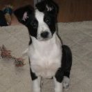
Thanks! Fursnake (that's her name, my wife named her) hasn't been as interested in hanging out while I'm at my bench lately. But if I'm reading in the living room, she's there.3 points -

WWII Luftwaffe maritime camouflage colors question
D.B. Andrus and one other reacted to Andrea Ferrari for a topic
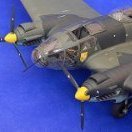
I have been postponing the building of my Revell 1:32 Ju88 A-4 and He111 H-6 for ages since I started having doubts about their proper camo colors - as I want to model both in continental coastal service, should they be finished in RLM 72/RLM 73 as all maritime aircraft proper (such as the Fw200 Condor, the Blohm & Voss 138 or the Arado 196) or in the customary bomber scheme of RLM 70/RLM 71? In other words, does anybody know if the maritime scheme of RLM 72/RLM 73 was customarily and officially applied at the factory on airplanes batches earmarked for over-water use even if the models were not originally built as such? As we all know, both the Ju88 and the He111 had versions specifically built or factory-adapted for maritime, coastal and general over-water work such as torpedo carrying - my question is, would these be factory painted in the maritime scheme of RLM 72/RLM 73 or just conveniently finished in the land camo scheme of RLM 70/RLM 71, as usual? Opinions - possibly supported by hard facts or official documents - much appreciated, thanks !2 points -
I once took a video from the right cockpit seat of a turbo Otter during takeoff, I could see what the camera could see (digital camera) when played back several hours later there was a prop blade not moving and stuck at about the 1:00-1:30 position on the camera viewer. By eye I could see nothing of the prop during take off and flight... weird2 points
-
That looks excellent Max! Great work, and lots of innovative solutions!2 points
-
No, I put a post up in the Venders forum asking if anyone had one for sale and another member sorted me out.2 points
-
At least tail looks centered and squared. :-)2 points
-
Here’s the fit up close. So it may mean that the trumpeter kit is a little too narrow, OR, the Hasegawa kit is a little too wide.2 points
-

Mil Mi-24 Hind Tiger Meet
BloorwestSiR and one other reacted to LSP_Kevin for a topic
That looks fantastic, Carl! Great work. Kev2 points -

Italeri F-35A in Thunderbirds Attire
Uilleann and one other reacted to themongoose for a topic
This is nearly all out of the box, a few scratch built parts to add some detail in the cockpit is all I added. I used the decals from the Tamiya F-16 Thunderbird to make up for anything I couldn't do with graphics. I used Maketar paint masks for all the scallops & curves on the bird and 3M fineline tape to connect everything together. I used MCW (Model Car Works) lacquer paints mixed to the correct FS colors for the Thunderbirds. The nozzle and cockpit is done with Vallejo paints and varnish. You can find a detailed work in progress build in Group Builds: Stars and bars. I decided to do tribute to the outgoing F-16 and I found the perfect art on the USAF site. This poster was created by SSgt Jon DuMond of the USAF Thunderbirds and they had a 3mb file available for free download, perfect. The key for me was the 2 F-16's outbound in the visor reflection. I used watercolors to blend the photo into the base and wrap it up into the F-35A Thunderbird. My bird is the Solo Lead with pilot and crew from the 2004 season reflected on the F-35A. I hope you enjoy these. I keep learning from everyone elses posts so I I've tried to add detail in the WIP that may be useful to others. If you see something you'd like to know more about drop me a line. And if you know the secret to the perfect build, or even a few of my model building dilemmas as detailed here, feel free to post it up. Chris2 points -
MH 60 Academy SeaHawk. 1/35 scale.
themongoose and one other reacted to shark64 for a topic
2 points -
Test shot of the 2000C... https://www.facebook.com/groups/369828906819827/permalink/654015201734528/2 points
-

B-17G + all detail sets from Eduard
Martinnfb and one other reacted to Miloslav1956 for a topic
Last update!2 points -
1:200 USS Missouri Build Log - Trumpeter w/ Pontos Detail Sets
Greg W and one other reacted to steinerman for a topic
Here's post #2 of this set: A lot of people have asked me what I'm going to do with this ship when I finish it? Truthfully, I have no idea! I definitely am going to enclose it in a protective case to keep the dust off, but other than that, I haven't decided. I'm thinking of possibly displaying it for a while and them possibly donating it to the Veterans Home here in Grand Rapids. Who knows - that's a long ways down the road. The light gray deck is in place just so you can see where turret #2 is located. Nothing has been done to this part - it's just as it came out of the box. Aside from all the brass parts, the entire ship was this color. Everything except the decking (which is real wood, by the way) has to be painted either Haze Grey or Deck Blue. Here's a closer look at the foredeck and anchor chains Adding the 6 chain stops was a real pain in the you know what! The little red things with white handwheels are high pressure fire suppression water valves. As I said before, the deck railing has not been added, nor has the 20mm AA guns and flagstaff at the prow. This is a close-up view of the foredeck just behind the anchor chains, showing the various detail on the main deck. First are the windless and brake controls, then the (2) 20mm Oerlikon anti-aircraft guns, various hatches and vents, and then the (2) quad 40mm Bofors gun positions, along with their respective gun directors. The storage boxes are ammunition lockers for the respective guns, and the torpedo shaped things behind the 40mm gun tubs are the (2) paravanes This is a shot of turret #1. There is a structure that is located between turrets #1 and 2 on the main deck that has not been added yet. It won't be added until Deck #1 is glued in place. I glued fender washers under the deck and magnets inside the turrets to hold them into place. That way they can be rotated and removed if necessary. The gun barrels are brass, believe it or not. Yeah, I know, why would you pay for brass gun barrels and then paint over them. I'm sure all of you know why!!! This shot shows the back side of the breakwater and the equipment located there. Also, note the helmets for the gun crew and the loudspeakers mounted on the rear of the 40mm gun tubs. A lot of this detail was added by me and did not come with the kit. I have a set of plans for this ship that are 9 feet long that shows all this extra detail. Here is turret #2. It has a 40mm gun position on top of it where turret #1 does not. You can see why!! Also note the 20mm AA guns on either side of the ship. The small diagonal tubes mounted on the front of the splinter shield are spare gun barrels. Cooling tubes for hot expended gun barrels are located inside the splinter shield, as are more crew helmets. The two valves just aft of the splinter shield are refueling ports for when the ship is refueled at sea. all this is extra detail that does not come with the detail kits. Overall view of the starboard side of the fore main gun battery This is the part I'll be working on next. There is a ton of brass detail that gets added to the sides, along with wooden decking similar to the main deck. I also plan to grind off some of the doorways and show them open with brass doors. The (4) rectangular protrusions along the sides are where the 5" gun mounts are located. There are 10 of them on this deck and the one above. This is just astern of Deck #1 and the location of turret#3. There's a lot of detail around here including 20mm and 40mm gun positions, winches, hatches, vents, hose reels, and fire suppression equipment. The long, grey device on the side of the ship swings out and ladders lower to dock small boats that come alongside. OK, this is another 10 photos. There are 6 more which I will post in the next one - #32 points -
1:200 USS Missouri Build Log - Trumpeter w/ Pontos Detail Sets
Greg W and one other reacted to steinerman for a topic
Howdy Ladies and Gents, It's been a while since I posted pictures of my battleship. I thought I'd update you on where it stands now so I got out my tripod, cranked up the f-stop on my camera, and took some decent pictures for once. NO, I didn't do all this since my last post! This series of pictures (26 in all) will bring you up to date to where I currently am. From now on however, my posts will be a lot less frequent because a) it took me 2-1/2 years to get this far, and b) I AM working on my Monogram 1:48 B-17 at the same time. I just don't have anything interesting to post yet. So, here is my "Plastic Toy Boat" as it stands today. Hope you find it worthy: Here it is - 4-1/2 feet of pure enjoyment. At least for me. I love doing this. My big thrill is building models. Once they're finished, yeah, I take pride in them, but sitting there looking at them isn't like the work of building them, right! There are (2) 20mm antiaircraft guns and a flagstaff that are supposed to be at the very bow of the ship. Because I keep the ship covered with plastic for dust purposes, I haven't mounted these yet for fear of knocking them off. Note the railings along the hull are also missing. They won't be added until the ship is almost complete. In this next photo You can see where I made a big mistake. There is supposed to be a ladder made up of individual grab-irons up the hull at the stern. With the handling and messing around, half of them have been knocked off, reglued, and knocked off again. I'll fix this, but I'm going to wait until near the end so it doesn't get damaged again. The screws are real brass and the silver rectangles are anti-corrosion plates. On the Iowa Class battleships, the inboard screws were 5 bladed and the outboard screws had 4 blades. Also, the starboard screws turned clockwise while the port screws turned counterclockwise. You always thought a battleship was gray, right? These are the actual colors of the USS Missouri in September 1944, when Japan surrendered on the deck of this ship The chain hanging down from the bow is called a "Paravane" chain. Paravanes are towed from the ship and are used to bring floating mines to the surface where they can be detonated by gunfire. A view of the foredeck up to gun turret #1. The deck in front of the capstans is steel and the remainder of the decking on the ship are teak boards. OK, that's 10 pictures for this post. More coming on post #2 of this set.2 points -

Wedding pics!
Model_Monkey and one other reacted to MikeMaben for a topic
I pictured this ... Another one bites the dust Congratulations sir.2 points -
Hello, I come back to the Breguet, work on the pilot's seat, copper wire and milliput. Now waiting before sanding and finishing. The fire wall which are not easy to made, it must think to the mold it and the resin casting.2 points
-
Mil Mi-24 Hind Tiger Meet
Rick Griewski and one other reacted to BloorwestSiR for a topic
Here's the seam after sanding. I then installed the engine covers. These are supplied clear so I gave them a quick spray on the inside. The fit here was really good. Which was a nice surprise. Next up will be the nose turret and some of the various sensors.2 points -

Eduard Bf-109 E-1/E-3 Legion Condor in 2019 announced
Rick Griewski and one other reacted to esarmstrong for a topic
^^People, including myself, have no interest in badly mismanaged forays into 1/32 scale.2 points