Leaderboard


Popular Content
Showing content with the highest reputation on 10/18/2021 in all areas
-

1/32 Tamiya Nakajima A6M2-N RUFE
Cicciuzzo and 17 others reacted to miketippingmodels for a topic
1/32 Tamiya Nakajima A6M2-N RUFF the resin float is very heavy and was connected using pins top and bottom, the resin its self isn't very good, its detail is lost in places and needed re drilling and rescribing, any way enjoy Mike18 points -
Thanks everyone Can't believe it's been over a month since I last updated - life has got in the way, with a bit of returning to the office in London for the day job (sadly..) Well thansk OBG, they are really useful and high quality - much appreciated Hi Craig - I wish I could make them! No, I get things like that from RB Motion - they are car bits and the site is worth a surf for bobbins like that So the build has lurched from highly precise focused detailing, to low end agrigultural heavy engineering.. I was getting carried away in the cockpit at a time when there is still loads of basic structural stuff to be done.. ..first up, there is nothing for the UC bays - these are unfortunately really complex so I am going to have to simplify when the time comes to detailing as otherwise I will be in there for months on end.. ..they don't look so bad here, but trust me there is a lot going on both structurally and in bits & bobs credit to the photographer shown ..I started by taking a slice of the plan drawing I have and drawing out the area I need to cut out that sits below the skin - also added ribbing locations as far as I could determine from photo's ..then cut into the balsa cores - you can see the brass reinforcement plates put in ages ago to hold the gear legs later.. ..you can also see how the wheel cut-out area eats right into the fuselage exposing the structure and lego blocks in there (!)... ..floors were marked out in card with the rib positions.. ..after the floors were added, walls were added and a few gaps & dinks filled in.. as the wings slide on and off the wheel bay area is fixed to the wing but slides out from the fuselage as one.. ..and with a shot of primer the basics are there to build on - I have a guy coming from Axminster lathes on friday to fix my little C2 (no power) so hope to start turning the legs and epoxy in the mounting stubs in the next few weeks ..the next bit I had been putting off are the mould bucks for the transparencies - if you see the shape of the main hood you can see why I was stalling.. ..I also found this drawing which I took as good enough to get some profiles.. ..first step was to get some outline boundaries from the plans and translate them to 3D so I can see basics like the angle of the windshield and the shapes generally.. ..I made up a plastic card frame with flat parts front and back so the blown bit starts at the right point - this is coloured black with a sharpie so I can see my sanding limit after I fill it - if you don't the card is white when you hit it and stays white while you sand right through the boundary (tell me how I know..).. ..filled with P38 and first pass sanded.. ..primered and nearly done - the blown bits look ok in the end.. ..same with the rear - balsa used to save on filler.. ..and this is where they are at.. ..anyone who has seen my build logs will know I HATE doing transparencies - they are my nemesis.. I spoke to John Wilkes (Tigger) and got some great advice on how to turn these masters into masters to actually get good pulls from. The main problem now is that these have a lot of filler & primer and the heat of the plastic causes that to melt, deform, delaminate onto your canopy etc. What he said was use them to get one good shape pull using PETG and the fill that pull with Filler like Herculite to make a better master that can take the punishment.. so that's where I am at - until next time Peter12 points
-

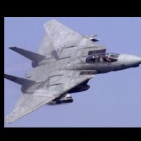
REVELL 03847 1/32 F/A-18F SUPER HORNET : some brief reflections
Supersonic and 10 others reacted to katana for a topic
Gentlemen , have aquired the 1/32 Revell F/A-18F. This is my very brief encounter with it : First impression : very nice kit. High grade of finish. A LOT of parts. A BIG instructions booklet. Nice decals. Kit instructions tell you to remove flash. Which flash ? What flash? Who's flash ? This is a brand new mould. I see no flash. Whatever... I did not remove any big parts to do a test fit, so I have no opinion on the real fit of those. An eyecatcher : You get DOUBLE parts for the Leading and Trailing edge flaps. More precise : you get each time 2 halves for : 2 x LE Outer Flaps extended or retracted. 2x LE Inner Flaps : extended or retracted. 2x TE Outer Flaps extended or retracted. 2x TE Inner Flaps : extended or retracted. Must say that the flaps halves are quite "soft". I never saw styrene THAT pliable. Also worth of mentioning: you get a special rectangular profile that connects the 2 short square axes on which you have to install the horizontal stabilizers. Nice piece of art. Although the purpose of it is quite OK to me , it looks a little " vulnerable". What I want to say : the Mechanism is a nice piece of engineering, but you should not forget WHY it is built for. This kit part has only 1 pupose. In the specific time frame of the kit assembly , when you install the frame , it stays there : see instructions page 14 , step3A The ONLY moment when it will serve is visible on page 58 in step 146 (!!!) . You have to attach the horizontal stabilizers to the square pins. I hear some people say : So , Is that a problem ?? No. Not now. Maybe later. My point is : do you have ANY idea how big a horizontal stabilizer of an F/A-18F is in 1/32 ? Now ,If you take a look how "small " the square profiles are from the support ( +/- 2mm square side ) , I guess you 'll understand what I mean. Step 146 tells you to mount the horizontal stabilos on the square pins. That is a whole bunch of plastic stabilo for a tiny plastic pin. will this lead to a pin failure ??? I have to be honest tough : the way the pin support is enclosed by the turbine outlet tube halves ( page 15 , step 5) will also contribute to the strength of the assembly. I admit. But it can NOT change the dimensions of the square profile where you have to put the stabilo's on. Never. Is there a remedy ? Maybe. I 'll carefully trace the center of the square and then I drill a hole trough the entire square pin length,the hole being 0,1 mm bigger than the metal pin I'm going to insert and glue in that hole with superglue. Then cut the steel pin at length : finished. Tiny square plastic profile from the outside, strong steel pin on the inside. Stabilo proof , I would say. Beside looking at the stabilo supports I also checked the inventory of the sprues, with the instructions. All sprues mentioned in the instructions were present in the box. There are even MORE plastic sprues in the box than the instructions mention: Sprue M ( not present in the instructions ) delivers the parts for the Aft cockpit instrument panel in PRE -ACS version = flat above. The aft cockpit POST ACS ( Lot26) instrument panel is present on sprue L , which is mentioned in the instructions inventory.It should be installed in the cockpit on page 28 via step 28a. Also discovered : a little bit confusing but not less visible : there are 2 (two) sprues named B. One with the " bard stacks and Stabilizer Support parts and another with the crew boarding ladder and NLG strut parts. Now , are all these remarks a black stain on the new REVELL F/A -18F ? Not in a 1000 years. Let's stay serious. This is not a build review , that's why I call it a "brief encounter ". It's the short overview of my impressions when opening a new kit. Not more . Not less. I'm sure not much later , some very handy modellers will give you a detailed build review from this kit. But in the mean time , Have a nice day !11 points -
Getting closer to the finish line. I added arming wires to the 1,000 lb bombs (for some reason not many folks add these), finished up the weathering on the underside (I think), added the landing / ID lights on the lower wing and added the machine guns. The Jug really does look bad-ass with those 8 .50 cals sticking out. That's it for now, thanks for checking in.10 points
-

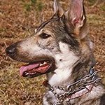
F-4D Spook on Spook
themongoose and 5 others reacted to David Mooney for a topic
Hello all, I've been working on this one for a while now and i was hoping to get outside and get some photo's on a diorama and in daylight, but the weather hasnt been playing ball. So, i thought i'd get some indoor pics done and then update this later. The build includes Red Fox Studios instrument set and all the weapons are attached with magnets for ease of transportation, paints were from Gunze and oil washed with Abteilung Starship filth for the most part. All comments welcome :-)6 points -
Just started a build for my little boys room. He is still afraid of the dark, and me being in dad mode came up with a simple strategy. How about put not one but two 32nd scale A-10s over head his bed and tell him they are on station to provide CAS to keep him safe. So with today being my birthday and having got these yesterday as my self bought gift, I decided to start the N/AW first.5 points
-
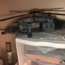
MH-6M little bird with crew
themongoose and 4 others reacted to matt_1185 for a topic
Just about got these two guys complete. Not gonna glue them on till I get rope made up and attached… they look a lot better in person also lol using phone to take pictures..5 points -

Zvezda Star Destroyer - a new detailing project
Alain Gadbois and 4 others reacted to The Madhatter for a topic
Well, the experimental masking is done and the results are here. There are some panels which require a paint touch up because - as feared - the paint was too thin for the masks and ran under them in places. Lifted the paint off in others. Over all though, I am pleased with how its turned out. I'm still debating whether or not to run a very thin filter coat over the whole area to tone down the enhanced panels. I still have small detail painting, washed and dry brushing yet to go, so the look will change even more but what do you guys think? Should I leave them like they are or run a filter over the top? Those longer roof panels are on back to front, so ignore those and yes, I did see the tape I left behind which has since been removed As always, thanks for stopping in and having a look Till next time5 points -
The resin parts are well worth the getting, if you can still find them. I've managed to get a correspondence going with Zactoman Chris who suggested he may be able to produce a seamless intake in the next few days, mailing time is the variable here. I decided to push ahead with what I could do, so splashed some paint on some parts I swear it doesn't look as crude in person, the camera is an unforgiving mistress. I used 1/48 RBF flags because they looked better (less prominent?) in the cockpit and, yes they are in English (sorry to those who insist on proper accuracy)Tamiya and Vallejo acrylics doing all the heavy lifting here. There's so much detail in the gear bays that it should take a proper modeller weeks alone to build and paint...I may have missed a few things, although hydraulic lines have yet to be added Thanks for looking5 points
-
Trumpeter 1/32 A-10 Night / Adverse Weather build
Starfighter Jock and 4 others reacted to Tyrant05 for a topic
More progress this morning. I honestly can say after never having built a trumpeter 1/32 aircraft before, I’m absolutely loving this build! I see some small corrections I’m going to have to make, but they don’t seem very complex and look to be easily solved.5 points -
1/32 TORNADO GR4
FreightDog and 3 others reacted to O.W for a topic
4 points -
A-6A Intruder Trumpeter 1:32 as always, is made straight from the box without any additional resins, but with aftermarket decals.4 points
-

Fiat CR-42 Falco, by ICM - Completed
dutik and 3 others reacted to Dpgsbody55 for a topic
Engine work continues. If you look at the picture at the end of my last update, you'll see the lines I've been trying to replicate at the bottom of the reduction gear housing. The Eduard etch kit supplies these but they have a number of issues. Firstly, they're flat and secondly, I think they're too short. I also think now that if I were to use them, the time to install would have been before I glued the reduction gear housing to the front of the engine. That way, the bending into place would have been easier. But I'd have needed to paint them after installation, and I'm sure that would have messed up the rest of the engine. So I made my own. There are eight lines visible in the pics I've found, one to each front cylinder, and one through to the back of the engine. Whether the back cylinders have these lines I'm not sure as I've not found any pictures suggesting their existence. And anyway, I don't think they'd be visible, so a waste of time and wire. I used 0.3mm soft wire, and after much cussing, squinting and an almighty headache, here's what I've got. Since they'll be seen through the open front of the engine cowling, I thought it important to add these in, and I'm reasonably happy with the result. But after doing these, the spark plug leads were much easier, though I'm not quite as happy with those results despite taking more time with these so as to remain headache free. On the real thing, the plug leads are run along the inlet manifolds and held in place with metal ties. I found it impossible to replicate these ties to my satisfaction, so I've left them off. The other thing, which is more a consequence of the ICM kit design, is that there's no collector ring for the plug leads to attach to. That ring is in a part of the engine that is hidden from view in the kit, as ICM have chosen to replicate the outer skin which covers that part of the engine but ducts cooling air out of the aircraft. I'm OK with what ICM have done here as the alternative in providing the parts to replicate the entire engine and it's mounting would have made the kit more complicated and expensive. In the end, I've drilled into the back of the engine and attached the ends of my plug leads here. Here's the results viewed from the front: I've also added an etch engine plaque. Here's the back, which I'm fairly confident won't be visible once the model is finished: The next step was to add the exhausts, which are not quite Tamiya quality. I had to wrestle the exhaust tubes into most of the cylinders and I found that the best way to get a decent fit was to drill out the holes visible in each head from 0.9mm to 1.1mm, though three needed further drilling out to 1.2mm. Here it is viewed from the front; and again from the back. No rocker covers yet. I've also been painting the engine cowlings in the colour I love () painting so much. Here's a sample. Once I've got them painted to my satisfaction, I'll attach them to the engine before mounting the whole lot on the model. At the present moment, however, I'm inclined to paint the rest of the model, attach the undercarriage, then add the engine. As to the engine itself, I also only have the rocker covers to attach, but I think it's a case of attaching rocker covers or cowling, not both. This being the case, I'll attach them only to those cylinders not covered by cowling. That's all for now. The next update should be showing a complete engine assembly, with cowlings. Then back to the plane itself. Cheers, Michael4 points -
At least in Europe, Revell kits tend to become available at very reduced prices not very long after launch. Currently retailing at €45,- , I don‘t think it‘ll be long until you can get it for around €30,-. Never seen such deals with Tamiya, their P-51D is only available for around € 120,- . So with my ambitions and skills, it‘s a no-brainer, and I‘ll be getting one to make a Swedish J26 out of it4 points
-
If that's supposed to be a leather pad for the backrest - good god man. You have nailed it. I am not worthy.4 points
-
OK, molds are working. Lens will be clear.4 points
-

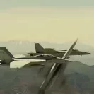
fleet week 2021
JeepsGunsTanks and 2 others reacted to dashotgun for a topic
I always wanted to go to fleet week. I am an avid photographer as well as model builder. This trip was planned for a long time but did not realize it was going to be fleet week!. The crowds were not to bad. I got a nice perch near pier 39 near some other photographers. FYI it was shot with a canon 7d mark2 with a 70-200 zoom mostly at 100 iso. I have near 700 photos from the that day alone so more to come if there is an interest or i can post the zenfolio address here3 points -
John - that is one bad-ass looking Thunderbolt - which surely is just the way you wanted it to be. I want to make a suggestion - to my eye, I believe the prop is protruding out a bit too far forward of the cowling, at least in the pictures you posted. Possibly this is because it is merely inserted onto the shaft and it is not seated completely? Anyway, for GE propellers, here is the way it is supposed to be: That 6.82 inch dimension is merely a measurement I took on the powerplant installation drawing 89P61003. It doesn't appear to be called out firm anywhere on any drawing. However there are several drawings that show the prop in a side view, and they are consistent with what you see above. Check and see how close you are to that .213 inch dimension (1/32 scale). If you are significantly over that, I think you can easily make the modification. BTW - you may know this already, but the GE prop installations sport a "brush housing" that fills the gap between the back of the prop hub and the front of the engine: And it gets worse - Note the "brush assembly" above, which mounts to the side of the brush housing, and has an electrical cable dangling from it. I have never seen these features modelled by anyone, save myself - I did it in 1/18 scale: It appears to me you have some sort of representation of this housing, but I cannot tell for sure. I don't think any model manufacturer that makes a P-47 has this feature modelled, for the simple fact that Hamilton Standard props do not have this thing at all, and that prop hub mounts directly up against the engine, and most manufacturers provide both props in their kits. I am not suggesting you do all this added work at this stage, but I am suggesting you check that .213 dimension. Once again - superb Thunderbolt. You should be proud.3 points
-

DACO 1/32 Fouga Magister?
Rockie Yarwood and 2 others reacted to quang for a topic
Adding up to Thierry and rafju’s input, this superb, 200+ page book from Serge Van Heertum released in 2007. Very interesting from a modeller’s view with insightful, instructive text profusely illustrated with detailed walk around photos and superb in-flight views. Text in english, french and dutch. Cheers, Quang3 points -
LOL ! ( Yes I AM reading this) I'm doing it in 1/32, 1/48 & 1/72 in limited numbers ( because that's how I roll). There's one on eBay right now to drum up finance for further work. https://www.ebay.com.au/itm/194447123175 Here's the work I just finished on the 1/48 accessories set which is being test printed as I write this and some examples of where the masters begin life.3 points
-
You too ????3 points
-

Wedell Williams type 45 1935 from scratch scale 1/32
Greg W and 2 others reacted to Marcin_Matejko for a topic
The models presented in the photos are polished. Meanwhile, "Concrete Mixer" put on the putty3 points -

P-47 Questions
Dpgsbody55 and 2 others reacted to TAG for a topic
Hello again, John Here's a couple of period color photos of 56th FG birds that show the wingtip lights, note the YZC finish (I've seen the rare green-tinted ZC finish here and there but the majority of these were in YZC). Also of note is the dark neoprene tape, either black or a very dark gray, to weather strip the edges of the clear part. Most modelers miss this detail and it is quite prominent in the 1:1 version of the Jug. A couple of black & white shots to illustrate this, plus an excerpt from the dash 4 parts manual for further corroboration. Looking forward to seeing you wrap up your badass Little Bunny/Norma build! Cheers, Thomaz3 points -
I like the way that the light reflects of this one. Derek3 points
-
DACO 1/32 Fouga Magister?
scvrobeson and 2 others reacted to quang for a topic
I was at the IPMS Belgium Nationals yesterday saturday. Too bad I missed the Fouga book (and Thierry Laurent ) Here’s Master Danny and his forthcoming baby Cheers, Quang3 points -

1/24 Airfix F6F-5 Hellcat "Kicked Up A Notch": New eBook Now Available!
Maw1963 and 2 others reacted to chuck540z3 for a topic
October 14/21 I’ve been a modeling machine the last few days! Colder weather and not much to do outside = more modeling inside, especially with the shorter days. I assembled the left lower wing much like the right one shown earlier. Unlike the right wing however, I didn’t carefully sand down the many ribs that will never be seen again, so I used a #11 knife and hacked away at will. Not pretty, but very effective and a lot quicker! One thing I should have mentioned earlier, is on the recessed outboard gun shroud, Part G40 or H40, they should be tilted slightly downward when gluing them in. This was discovered when I placed the upper wing on top of the lower wing and checked alignment from the front. Just glued in as per the instructions will result in misalignment. You don’t want to see any of the front part of the shroud when looking through the gun hole and tilting them downwards eliminated any of that. This kit continues to amaze me by how some parts don’t fit very well, while others fit like a glove. Here is the interlocking join at the top of the two wing halves when placed over the central fuselage assembly in Step 103. They just slip together perfectly, creating a solid join that won’t move later. I then dry fit all of the wing parts together in a bit of a trial to see what I was up against in the near future. In Step 104 and 105, I had to laugh when the instructions suggested that Parts N30 and N34 may need their surfaces to be “filed, if required” to allow for sliding into the lower wing and central assembly in Step 108. No kidding, they needed to be sanded down about 20% on every surface before I could get them to slide into anything. One tip is to cut back the bottom notched tab of these parts (top in pic below) to allow the lower wing to slide into the central assembly at an angle. Otherwise, all sorts of tabs on the wings will get in the way and you don’t want to be fooling around with the fit when you have committed to glue. After many hours of getting all the wing parts to dry fit together, the wings look terrific- and long at 21 ½” wide. This size of this model has slowly snuck up on me, because it’s going to be huge and photographing future steps in my small photo booth will be a challenge! A closer look. The bottom. All of those gaps will close up once I commit to glue, or at least I think/hope so. With the wings dry fit, I thought I would check how well the fuselage would fit on top. Not bad, but there is a big gap at the front. Same on the bottom at the rear. Like everything else on this model, the problem lies with joins that fit too tight. It turns out that the forward cockpit floor is too wide, so it was trimmed back a bit, as where the two tabs at the front. The two inserts at the top of the wings need to be widened as well. Here you can see where the cockpit floor fits between two sills, which you can barely see from the top of the cockpit. As a result, these areas should be painted Interior Green before gluing everything together, which is not mentioned in the instructions. Everything fits together pretty good now and with a bit of glue, it will look a lot tighter than this. No wing roots seams to fill for a change. Hurray! Same for the bottom when dry fitting. With some glue and a bit of pressure, there should be no gaps. Now that I’ve got everything to more or less fit properly, the next step is to paint the wheel wells and anything else that will be exposed underneath. Unfortunately, everything will be gloss dark blue like the rest of the aircraft, which is kind of boring and details within will be hard to see. I also need to insert 2 formation lights at the top of the wings and the landing light at the front of the left wing before I commit to glue. While I have pics of the landing light and generally know what to do with it, the instructions do not tell you what color the formation lights are. A query in the Aviation Forum reveals that they are blue, which is why they are hard to see in pics. More blue against a dark blue background….. One thing that you might find missing from this build is a lack of Tamiya Panel Line Accent Color that I usually apply to show all the panel lines and rivet detail in my builds. I do this when adding or repairing panel lines and fasteners, to check for flaws. For this kit, it’s a waste of time because every part has nice crisp detail that needs no enhancement and panel lines mesh perfectly, which I’ve never experienced before, including on my Tamiya Spitfire and Mustang builds. Overall, this has to be one of the best kits made ever. I’m really enjoying this kit so far and despite my complaints about tight fitting parts, I would much rather have them tight than sloppy. I can tell already that if I don’t screw it up, this will be a very impressive model to add to my growing collection. Now if I could only find room for it….. Cheers, Chuck3 points -
work...such as it is, has begun on the Sufa, I've unpacked and begun cleaning up and working on the resin bits I've picked up over the years for the kit. the Aires instructions suggest removing the molded in kit part to fit the nose gear bay, anyone familiar with the tight fit of Aires will know my struggle. I duly removed the molded in nose gear bay, sanded it smooth and then began the cut, sand, test fit repeat method of installing the bay. A picture speaks (many) words so I'll show a couple of images of that work. The intake trunk/ nose gear bay removed and sanded quite thin, I've also cut a relief into one side to lower the gear bay away from the intake trunk, the other side was also undercut. After a bit of work...I got the gear bay fitted, figured I should test fit the main gear bay now as well the main gear bay appears to be a drop in fit. Thanks for looking3 points
-
Thank you all Well I better do an update then Cees when I left you last, I was working on all the little bobbins in the cockpit - switch panels, control boxes etc - most of these are PE faces, custom decals & toggle switches from wire, some of the bigger knobs & buttons are modified watch parts (cogs & shafts etc)... ..these are the front cockpit right hand side.. ..and fitted - the fuse panels in the lower half were first made up, then finely chopped coloured wire dropped onto blobs of CA - a bit like decorating a cake with hundreds & thousands.. ..same for the left.. ..here the knurled wheel was a modified 1/24 tailwheel (Fw190 i think) with ribs added.. ..rear right.. and rear left.. ..the rear bulkhead has quite a lot of complex work and it's own buoy and target towing control panel - the yellow thing in the middle is a pull cord to cut the towing cable.. ..when dry fitted in the airframe it starts to look like this.. ..then as we modellers like to do, we start to cover it all up.. ..here with the upper decking.. ..and when built up the cockpit starts to look a bit busier - in all areas there is still quite a lot of cabling & wiring to add.. ..and thats it for now - until next time.. TTFN Peter3 points
-
Good morning lads, I finally finished my new summer project GWH's 1/48th scale T-33A. My time was limited to present you an in progress work, but i will try to give you an idea !! The kit and some aftermarkets...also used some custom masks for the ''USAF'' and ''TR-411'' codes from my friend Alexis And the scheme i am for is the second one TR-411, here is the only photo i managed to find.. A few words about the kit....AWESOME!!! (my humble opinion!)....nothing more A few words about Caracal decals...the same!!! Awesome!! I started dealing with the cockpit as a usual...here i used Eduard PE for the cockpit and the pilot's seat! Cockpit... Seats... All together and weatherd... Wheel wells and flaps... I also used Eduard PE flaps, i decided to pose them down.. ....2 points
-
After watching the new "Midway" movie last year I decided to build USN Lt Richard Best's SBD-3, that he flew twice from USS Enterprise, on 4th June 1942 to sink the IJN carriers Kaga and Hiryu. Its a really nice kit, but I didn't particularly like the clear fuselage. Nothing wrong with it but just hard to see if seams are covered until undercoat applied. Painted with a combination of SMS, MRP and Mr Hobby acrylic laquers and then weathered with oils and hard pastells. Yahu instrument panel, EZE line antenna, MasterCasters wheels and Master gun barrels. Some light fading on the upper surfaces, but these aircraft were new when they boarded Enterprise immediately before the Battle of Midway so not too much to do. My model depicts what the aircraft may have looked like after returning from the first attack and ready for the second sortie. The rear guns would have been stowed but I wanted to be able to see them. Enjoy.2 points
-

Mottle Camouflage for BF-109E-4/7 (North Africa)
thierry laurent and one other reacted to mozart for a topic
Freehand it for sure. What's critical is the correct consistency of the paint (if like me you use MRP this isn't an issue) and the pressure on the airbrush, I used around 10 psi and a very light touch on the trigger:2 points -
At that price - I'm in! Y'know, I'll have to buy a kit to go with the AM I have... Richard2 points
-
Blackbird Models produce an early Hunter set.2 points
-

Reference for Hunter f.4
Derek B and one other reacted to crobinsonh for a topic
Hi Richard, You can absolutely get away with cutting down the dog tooth leading edge as that is what I ended up doing on the F5. Whilst I did fit the resin tailpipe it was not great quality and did not really capture the under swoop of the F5 version. Next time around I would certainly investigate if there was a better conversion.2 points -

Make the others jealous
Panzerwomble and one other reacted to Jeff T for a topic
No LSP stuff unfortunately, but a couple of items for some Armour builds I am doing. 1/35 Friulmodel M-42 Metal Tracks for the AFV Club Duster, and a set for the AFV Club Centurion. .....And the Voyager PE Set for the AFV Club Duster,....this is very comprehensive, I dont know how much I'll end up using out of it. Cheer's, Jeff.2 points -
Well Kammeraden, now I've got no excuses alibi. Best get busy!2 points
-
Well it’s an honor to have you aboard! There will be some corrections in store for the airframe as I get further into the build, maily because Trumpeter then Hobby Boss incorporates some A-6E features. All pretty easy! Thank you for passing along Capt. Fickler’s history. I know he would be honored by your build. Cheers, Tom2 points
-
Author Are you kidding me????? What a fantastic IP Peter!! I don't know why I was not following this build continuation, but I am now!2 points
-
40min or so...or perhaps you could suggest to Brendon I've not been to Biggin Hill for some time?2 points
-

RAF FG.1 XV571 WILD HARE Phantom Conversion
Derek B and one other reacted to easixpedro for a topic
Dig that shot. Shows the complex shapes that Anthony is capturing. Can't wait to see it come together with wings. Closed canopies would do a lot to highlight the beauty...and save you the dreaded cockpit work!2 points -
Another one signed on Tom, you're doing a magnificent job so far and I plan to steal borrow your tips here. I have the Hobby Boss 1/48 A6-A kit to build, in honor of a man shot down in one in January '69. I have worn a POW/MIA bracelet with his name on it for nearly 30 years, and have wanted to honor him by building this kit. His name was Capt. Edwin J. Fickler, VMA(AW)-242. Capt. Edwin J. Fickler MIA2 points
-
Panther V Aufs G 1/16 Trumpeter
Paulpk and one other reacted to josebagasteiz for a topic
Hello again everyone, I hope you are well. Now new photos of the interior of the Panther at 1/16 of a trumpeter. I have not painted some oil passages yet: Hope you like!!2 points -
Hey thanks for the information. I wasn’t aware that the kit came with the needle blade props. I did find another photo of RAAF forest green mosquitoes. Now I just need to finish my 1/16 Panther tank before I dive into something else. I have more ideas than build time I’m afraid.2 points
-
I thought about a lot of different ways to do that camo on my what-if 335. In the end, the best way it seemed to achieve the result desired, was to plot and plan the spacing, then set the airbrush on a fin/low PSI setting and do all the outlines first and then go back and fill the blotches in. In my case, I used a bit if an unconventional way, by using some various sized stickers from the local Hobby Lobby to get the size and spacing correct prior to spraying the actual blotches. After laying this down, I used a pencil to lightly trace the shape of each blotch so it was where I wanted it, and it fit well shape wise: Then, I just started coloring the blotches in, outlines first, then filled them in one at a time. There are a LOT of ways to do this camo, mine is a bit unconventional but worked well. Also, it really helps spraying a high quality paint. In my case I shoot exclusively MRP, and it lays down nothing short of a dream for me. YMMV, and hope this helps in some way.2 points
-

Mig-21 BIS Bulgarian Air Force
Martinnfb and one other reacted to ShelbyGT500 for a topic
HI Alain, well the nose-cone is wider than the MF's, not longer. I mean wider when write "larger". Sorry for that For fuselage-nose - yes it is wider than MF's also and the edge is "beveled". Maybe this is the right word. And for the spine - yes, wider and longer at the back side, where the tail it is. It ends almost where the parashute-tube starts.2 points -
Mig-21 BIS Bulgarian Air Force
Martinnfb and one other reacted to ShelbyGT500 for a topic
Thanks guys, well I do not like the "ready" colors sets from manufacturers. It's so far from truth. So every time I mix my own. About your question mc65, for "Russian cockpit green" I mix this two colors 50/50 ratio: And always you can change this mix, if you want more blueish or greenish shade of cockpit color. Cheers.2 points -
Mig-21 BIS Bulgarian Air Force
Alain Gadbois and one other reacted to ShelbyGT500 for a topic
Wow, Thank you guys everybody must feel excellent when people like his work Ok, no problem my friend. I've used a lot of 1mm polystirene and tamiya epoxy putty. First nose-cone: The exhaust and its "interior" : The re-worked fuselage-nose and MF back-spine: And start to shape the BIS spine: And already re-worked BIS spine, fuselage-nose and nose-cone: This was done maybe for five days, because the putty must be completely dry and hard. So hope this will be in your help at future bis projects Cheers2 points -
GWH 1/48 T-33A, 349th FB, Hamilton AFB, California, 1955
Rockie Yarwood and one other reacted to zaxos345 for a topic
I glued everything together, fit was really great!! Some sanding work needed but it was my fault, i did not prepared the plastic joints too good!! And it was painting time, i used Ak extreme metal for the metallic finish and , as i did with my F-86D, i sprayed it with very light passes on the bare plastic! of course i had prepared the plastic thoroughly for this work and i had also polished it with micromesh! Finish was awesome. a bit fragile, but awesome. I did not want a mirror finish bird, i wanted it a bit weathered and slightly used. The bare metal takes a beautiful patina over time and different on each occasion. It is never the same!! Everything painted so far Decals on... Weathering....2 points -
I'm building the F7F.........2 points
-
hi again everyone & thanks for stopping by Hi Will & welcome! thank you for taking a look, I expect like me, you will find your spiritual home in LSP - this place is just wonderful to learn, be inspired, laugh and hang out Hey Torben great to hear from you and do please restart with those shelf queens, always love to follow what you get up to I have been messing around with lots of little bits, but it's ok as it's all in the cockpit and I just lurve doing cockpits ..I took a look at the seat - I started this back in 2018 and used the base part as a basis for correction ..it's made of bakelite sort of stuff and needed the sides building out for these sort of 'wings' on the sides.. ..details, seams & rivets were added and the rear cushion made from milliput - the seams on this are lead wire and my sculpting skills are not very well developed ..then they were painted - lots of the tonal stuff seems lost in the picture.. ..also made the adjustment assembly & lower mount struts.. ..and it sort of goes here.. ..then made up PE bits for various consoles and fittings - many of these are in layers, much the same as the instrument panel.. ..after paint and decals I have a lot of work ahead still to do all the switches and knobs and make up the laminates plus glazing for those with dials.. ..speaking of instrument panels, I made this one from custome PE, custom airscale decals I tacked onto a trade order and lots of bits & bobs.. ..its as close as I can make it to the one in Steve Long's care in Oz.. ..yet to make the compass that goes in the compass stand.. ..long way to go yet, but it sort of goes here.. TTFN Peter2 points