Leaderboard
Popular Content
Showing content with the highest reputation on 02/23/2020 in all areas
-
When I was dry-fitting the cockpit to the fuselage, I was using bits of Blue Tack to hold the resin pit into place. It gave me a little bit of "give" to make minor adjustments. So I thought I'd permanently attach the cockpit in a similar manner using Milliput instead of Blue Tack. Hmmm... I forgot to take a pic of the buttoned up fuselsage! Attachment of the resin cowling to the fuselage is coming up so I thought it would be a good time to apply the rivets... After cleaning up the fuselage seams, I added a missing panel on the fuselage bottom using a piece of brass sheet as a scribing template. The shape for template was derived from a scan of a 1/48 scale drawing of a G-6. The scan was imported into AutoCAD, scaled up to 1/32 scale and a mask file was generated for the Silhouette Portrait. The mask was stuck onto a piece of brass and cut out with scissors. Once you get used to a piece of technology, this stuff becomes a bit ho-hum and I didn't record any of it photographically. The centerline seam was re-established and riveted.12 points
-

1/32 Marauder
Coneheadff and 10 others reacted to AlexM for a topic
Hello there, again little progress. One thing that causes headache is the main landing gear, which is angeled forward in a scary way, while the whole model is rather heavy, not least because of the counterweights to prevent the notorious tail-sitting. The green one, which is printed as one single part, is in no way strong enough, will bend and propably breake. I'm thinking about metal casting by a goldsmith, but I guess this wouldn't be cheap. So right now, I'll try a multi-piece landing gear with 2mm steel rod enforcement. The upper part of the fork now consists of two halves which cover a bent steel rod. There are still weak spots, but maybe it works. Whish me luck Cheers Alex11 points -
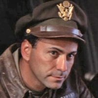
Hello all, Possibly not the fittest subject in this forum, still... The figure comes from the ICM British Pilots set of 3. Gone are the crude, puffy-featured, wooden-stance plastic figures of yore. These injected-plastic figures are on par with their resin counterparts while costing much less. The sculpt is competent, the details crisp and precise, the features...er, humane . This is my take. I altered the stance a bit and gave the pilot a little friend. I hope you like it. Cheers, Quang10 points
-
1/32 Marauder
Harrison90 and 8 others reacted to AlexM for a topic
Thanks guys! I think you are right, if everything else fails, a metal landing gear would be a reasonable investition. Meanwhile, I provisionally pluged the steel-rod-enforced legs and the small support struts into the the designated openings in the wheel wells for a first test. And right now, it looks promising. Not bending visible I'll leave it like this for a while to see if it stays stable. Cheers ALex9 points -

Forgotten War Mustang
R Palimaka and 7 others reacted to John1 for a topic
Just a few pics of (hopefully) better quality:8 points -
1/32 Marauder
Harrison90 and 6 others reacted to AlexM for a topic
Thanks, Mark! I know what you mean. I printed the parts with a resin that is advertised to be very strong. After all parts were glued together, I put some more liquid resin at the seams and put it under UV light to cure. Now, It's more or less one single resin part with steel-rods within. I'll watch it for some time and hope that is stays stable, especially at the weak point you mentioned. One nice thing is that the balance can now be checked to prevent tail sitting. Until now, the necessary counterweight at the area forward of the main landing gear has only been roughly calculated. Now, with most weight-relevant parts provisionally attached, it already stands like it should. And the resin engines and the forward landing gear isn't attached yet, so I think at least regarding that aspect I'm safe. The weight on the nose landing gear will be minimal, so a fully printed nose gear without metal-rod-enforcement should be fully sufficient. Cheers Alex7 points -
Trying to get back into actually building things again - have picked up on a Tempest I started a while back: Really enjoying this one - some very sharp/neat moulding - but parts still need test fitting and careful fettling at each stage. More shortly... Have fun. Iain6 points
-
The Special Hobby Yak-3 spinner and prop from Michael arrived yesterday, so I was able to finalize the 3D model of the last piece with the diameter of the spinner. I chose to print that piece because it was actually a very tough piece to build by hand, but Ironically, was extremely simple in the 3D software. And why print one, when you can print 5!! That way I can screw up 4 of them. After some slight modifications to the spinner to match the reference photo (I made more pointy and drilled the hole), time for a test install on the front piece: Looks good so far to my eye, so now a test fit altogether. I tried to replicate the angle of the photo: Nose is looking good, but I immediately noticed that the hump above the exhaust port is way too big!! I also need to cut that little hole just below the exhaust. So, on to re-shape the humps to a more realistic size. Tim6 points
-
One more detail to do before painting. I plan to arm my F-16 with AIM-9P’s. There are no such missiles in 1/32 except for aftermarket items. With our post it is not an option. Luckily the AIM-9L’s in the Revell F-4E kit are the right length for a P but not for an L ! Using the missiles in the Academy 1/48 F-4C as a reference I shortened the back fins by 2mm and scratch build the front fins. Only painting remaining now. Nick6 points
-
Thanks for that! in the mean time I have been thinking about a stand to hold this big beast. I have been looking at phto's of the beginning of the runway of USS George Bush. But it was the USS Theodore Roosevelt, on which the crew had painted 'IF YOU CAN READ THIS ADD POWER' that caught my attention. Good sense of humor of them! I think I would like to go for that too! some very good pictures from Kai Wolter and US navy btw. I made a print of a piece of flight deck, which I had drawn in CAD some years ago: \ Indeed that is my feet in the photo, gives you a sense of the size of this thing. Went to the DYI shop on saturday to get some wood and plastic. My project was just extended by a month!6 points
-
Last night's weathering over a few hours. I went to my local art supplies shop and bought additional pencils, pastels, charcoal etc. I began weathering around 9 p.m. and stopped around 1.30 a.m. a lot of that time was experimenting with my new supplies. Great fun. I would try something then another thing etc etc. At moment of writing it looks like this. My morning has been spent cleaning my work area and searching for the propellor. Will begin again now.6 points
-
So, first thoughts on the HGW wet transfers. MAKE SURE YOU BEND AN EDGE OF THE CARRIER FILM UP. Otherwise, good luck getting an edge to catch and peel up the film once it's dry. There are 1-2 that I couldn't grab an edge on, thankfully very small and I can blend them in. The carrier film is nice and thin at least? More work than a regular decal to ensure that the film stays up till it's dry enough.....then walk away, walk away! The transfers I added last night, need to see what else I can do to remove the adhesive. The film came off well this morning, but I can see exactly where the adhesive was. Any suggestions? Montex Reluctant Dragon decal.....went on perfectly and sucked into the rivets and fasteners with just Micro Set. One bubble in the film, stabbed with the #11 and some Micro Sol took care of it. This is all for now, just a quick snap from the Nikon. Now it's back to remodeling a bathroom for most of the day! You can see the carrier film sticking up in the air on some of the transfers.....gotta have that edge!6 points
-

Aussie/New Zealand A-4 Scooters
cib2265 and 4 others reacted to Anthony in NZ for a topic
Yes, that is I.... All the masters are complete, instrument decals done and with a well known resin producer. The upgrade will include all the antennas and a coaming/HUD to help you make a Kiwi scooter. I am under the understanding it is only a couple of months off production in the cue due to previous projects being cleared through. I am sure you will be happy with it as there has been countless hours go into measuring the panel, HUD and antennas, not to mention all the CAD work involved. Was a bigger project than expected and had I known would probably never have started it LOL Keep an eye out, it wont be far now5 points -
And here's where we are just now... Dry/test fit of the root intakes after clean-up. Fit is pretty good after a little fettling with a file and sharp blade. These were bonded to the rest of the airframe after the cowl had been fitted: And, after some further prep and lots of test fitting - both to the forward end of the fuselage, as well as the cowling itself: Tip: don't fit the gear door hydraulic actuators until assembly/prep of airframe is complete. Follow the instruction sequence and they are easily damaged - don't ask, I just know - OK? Damaged parts stashed away safely in a box for now... More soon... Iain5 points
-

1/32 Luftwaffe Oxygen Hose
D.B. Andrus and 4 others reacted to Radub for a topic
In the past I used guitar wire. You can get wires of a variety of gauges. However... In the recent years I learned that the "ribbed" hose is incorrect. The photo posted above depicts Bf 109 G-2 "Black 6", currently residing in Cosford. That hose is a modern item. The "Sauerstoff-Dusche (Membranlunge)" manufactured by Dräger used a smooth hose. You can see see the smooth hose in a lot of wartime photos and in many museum exhibits. Possibly the clearest example is the Arado 234 that has a long hose that is clearly visible. Go to this link of a 360 degree panorama of the Arado 234 cockpit and have a look at the hose on the right side of the cockpit. https://airandspace.si.edu/multimedia-gallery/10103pjpg There are more "walk around" photos of the Ar 234 on he internet and you can see it there too. There was, however, a "ribbed" hose on the oxygen mask. These ribbed hoses, which were very short, connected to the smooth rubber hose. See these links: https://airandspace.si.edu/collection-objects/mask-oxygen-demand-type-luftwaffe https://www.historicflyingclothing.com/en-GB/show-me-everything-/luftwaffe-model-10-6701-oxygen-mask/prod_15009#.XlI7VyieSUk So, to answer your question, you can use a piece of smooth wire to represent the hose leading from the regulator. If there is a pilot wearing a mask in the cockpit, you only need to make a short length of ribbed hose from the mask to the hose. HTH Radu5 points -

Tamiya F4U-1 Corsair as a FAA Corsair I, 5F JT 150.......FINISHED
MikeC and 4 others reacted to monthebiff for a topic
So a little more on the Corsair, I had originally sprayed the wheel wells in Salmon primer and was going to leave them that way but since back on the build decided to paint them white and then weather them a little. So with the u/c bay paint work complete I've mated the wing section to the fuselage and also added the tail feathers. Now need to get my ass in gear and work on the engine..... . Sad times as I hate engine build/ detail work!! Regards Andy5 points -
Another one that's been resurrected and making progress again, at last! This is the Pacific Coast model - have to say it looks better in the box than the build experience - lots of nips and tucks needed. This will eventually carry the markings of Battle of Britain pilot Desmond Fopp - the grandfather of one of my friends. Reshaped area on spine/rear of cockpit, canopy rails from 1mm brass extrusion - and I've had to reduce the height of the windshield by almost 2mm to get it to match the sliding portion. More when there's more... Iain4 points
-

F-35A 13-5081 AFB Hill
AnthonyWan and 3 others reacted to CruZz for a topic
Hello gentlemans. Model represent plane from AFB Hill nr: 13-5081. It was only one with some light weathering, when I build it.... Kit Italeri Eduard PE sets Lot of scratchbuild and wiring (wheel bays, bombbays), added many surface details. Wheels True detail... Amraams Eduard brassin. Paiting masks by DN-Models. Decals: Furball Etc.... I made my own exhaust nozzle od 3D printer, because all of aftermarket set was small.... Thank you for watching. Have a nice day. Jan :-)4 points -
Hi Mark, I see your point, I selected only a part the size of the aircraft out of the whole print: I just ordered some extra tie down points at shapeways, that will take a few days before I can progress.4 points
-
WIP here: Thanx for looking,4 points
-
Like many other modellers I've been quite taken by the WingNut Wings kits - and have been slowly collecting them over the years. Again, like I suspect with many others, they've just sat in the loft - with me putting off the day of reckoning where I actually have to rig a biplane - and with my prime interest being British and Commonwealth subjects - that's meant those 'orrible flat wires!! Just before Christmas I invested in the various sizes of flat wires produced by Radu as part of his RB Productions range and, well, if I don't start one now, I'll keep putting it off... So, Ladies and Gentlepersons, I give you the start of my first foray into the world of WingNuts - the "Le Rhône" boxing of their excellent Camel. I have four Camels of various versions in the stash, so I figure I can cope with one being used as a 'test mule' to see how it comes out. Learning/gaining confidence as I go - so please be gentle. Currently playing with wood effects - oils over MRP Light Wood - before I dive into detail cockpit painting. Great fun so far - we'll see how long it lasts, eh? Iain3 points
-
I finally completed the base for the Albatros. It took a bit longer then usual because we have gotten a lot of rain the past several days meaning high humidity. So it took a lot longer for the various coats of stain and varnish to dry. Overall the build turned out ok. I made a few mistakes, most notably simulating the different shades of wood on the propeller, which I airbrushed far too straight. But overall the aircraft looks the part and the figure turned out pretty well. The scene could be entitled "Post flight", as it shows the mechanic facing away from the cockpit area with barograph in hand. I will be pausing my WWI aircraft builds, because I have decided to build the HGW Limited Edition of the Bf109 E-7. Based on the thread concerning HGWs wet transfers perhaps working best if one does not let them sit in storage too long I thought it best to get a move on and construct the kit. After I complete that project, I plan to build the WNW Pfalz DIIIa. I am going to try out the Gaspatch turnbuckles to see if I am able of using them to do a decent job making the rigging look better than I did with the DV and DVII. Enjoy the photos!3 points
-

Gloster Gladiator 72 Sqn RAF 1937
Nighthawk Calling 1 and 2 others reacted to quang for a topic
This Gladiator K6140 wears the livery of 72 Sqn RAF as seen at Church Fenton in October 1937. The superb ICM kit was built OOB without aftermarket additions except for RB Productions Sutton harness. Basic silver paint: Tamiya TS-30 Silver Leaf. Silver dope on canvas parts: Alclad Flat Aluminium. Stock decals. Hand- painted squadron colours using frisket film All other colours: Vallejo acrylics. Rigging: elastic thread 0,25mm and 0,30mm Turnbuckles: Albion Alloys aluminium micro-tube 0,50mm You can follow the build in progress HERE Hope you like it, Cheers, Quang3 points -

Resin Switches and Knobs
Pete Roberts and 2 others reacted to seiran01 for a topic
Manufacturer is AnyZ - bloody good quality stuff, I have his whole line at home. https://anyz.io3 points -

MH-60L Black Hawk Kitty Hawk 1:35
Loach Driver and 2 others reacted to Koralik for a topic
This time a helicopter. Model Kitty Hawk MH-60L Black Hawk scale 1:35 Typical Kitty Hawk - cut into a million parts - what for? I have no idea. The model has a nice detail but unfortunately the model it's very poorly fitted. But the biggest problem is with decals. I can't understand why people from Kitty Hawk could add black decals to the helicopter in black color?3 points -

Special Hobby Tempest II
patricksparks and 2 others reacted to Iain for a topic
Talking of fettling - here's an example - the wing root intake sections. These are separate from the wings to facilitate differing versions. Moulding looks very sharp - but alignment of parts at their edges is variable - so it's a case of aligning the parts as neatly as possible and then truing up the edges once everything has dried overnight: And that beautiful Centaurus cowling - after partial clean-up and the addition of upper and lower infil panels: Iain3 points -
USN Blue-Gray fading on SBD's
Alex and 2 others reacted to D.B. Andrus for a topic
A color shot of an A-24 in OD 41 & Med Green 42 Cheers, D.B.3 points -
Thanks very much guys! Next up is the MG access door. The Tamiya part is a bit simplified and doesn't include the exterior locking levers (which should be extended when the door is open) and interior latches. Here's a pic that shows how the real thing looked. In addition to the door latches, there is a large handle next to the aft ammo feed. Also note the thin support rod on the right hand side of the door. I started off by carefully removing the recesses for the two exterior locking levers. When these are opened, you can see through this straight into the MG bay. I drilled a few holes with my pin vice and then used an X-acto knife to carefully remove the remaining material. I then used thin strips of PE to replicate the levers. As shown above, in the open position, they actually protrude through the opening into the inside of the door. One thing Tamiya does include is a nice decal that closely replicates the large loading instruction placard on the interior of the door. Here is how it looks from the frontal aspect. Sorry for the less than clear picture, I really need a better camera! Note that you can (barely) see all the way through the lever recesses. Also note the locking (I'm guessing) lever in the vertical position by the ammo feed tray. I replicated this from a piece of plastic card, carved, sanded and bent per the original. Also added some tiny bits of scrap PE and plastic for the mounting bracket. Here is how it looks on the backside. Note that the door is just press-fitted in place so the support rod is out of position. This will be in the proper spot once I glue it in permanently. Also note that I haven't done final touch-up painting and weathering. Sorry for the crappy pics but you can (barely) see the door's latching mechanisms. Also, one thing I neglected to mention before, later Mustangs (not sure if they came from the factory like this or were mod'ed later in life), had the fuel drain accumulator vent intake housing removed. In it's place was just the recess for the scoop and the drain opening. The Tamiya kit has the scoop molded to the fuselage (it will be interesting to see if they addressed this with their F-51D kit, the way the part is designed, I'm guessing they didn't). I carefully carved the scoops away (it's present on both sides) and drilled the drain openings. On some F-51D's, the recessed area was painted red, I'm not sure if my subject had this or not, still researching. Here is a nice reference for some late Mustang exterior mods. I'll be adding the g-suit opening and battery drain at the end of the build. And a final crappy picture. I'll try to post better pics later. As always, thanks for looking!3 points
-
'Flying Circus' - Jasta 11 (Diorama base)
D.B. Andrus and 2 others reacted to kkarlsen for a topic
The German Staff Automobil is finally up on it's 'wheels'. It's been a tough one and a lot of detailing is still needed... Cheers: Kent3 points -
Hi Everyone, Time to put this one to bed. Thanks for putting on the great campaign, LSP! Gaz3 points
-
Time to pick up were I left the 'dreidekkers' - Still got a diorama to do... The photo's I'm using as inspiration for the diorama: The 'walkway' in the front, that would be a nice feature to add. I also want to add a lot of crew and ground personnel. This is a nice shot showing the preparations for a 'sortie'. German staff car has been in the making, on and off, for some time now... This is were I left it, almost a year ago... The last week or so, I've had time to refresh and practice the spoke wheel technique to make some wheels for the car... The Fokker 'dreidekker' triple are ready. The half 'dreidekker' is ready as well... Hope I will be able to get somewhere with this in the foreseeable future.. Kent2 points
-

Soviet Pin-Up
daveculp and one other reacted to ShelbyGT500 for a topic
Hello guys For a short break from flying birds, I build this birdy The model is resin GK, 1:9 scale, with a lot of re-works and scratches. The blue cap is from milliput, a lot of scratch-work for the pistol, bayonette and the aks-74u build from 2mm plastic sheet and photo-etched parts from spare box And here she is: Hope you will like her Thank you always for watching. Cheers friends.2 points -
Aha, beware, friend Max, oils is a whole other ball game AND a new source of addiction Some facts: – Oils being slow drying, you can take the time you need to paint a face. I usually do it in 2, 3 sessions. – Paints are used wet-on-wet in VERY thin layers. – Do NOT dilute oils with turpentine or other thinner. Use instead a product by Winsor & Newton called LIQUIN which has the property to dilute the paint to the extreme without killing the pigment. –The thinner your layer, the shorter your drying time. Liquin also helps your paint dry quicker. Setting time is usually 1 day. The paint continues to cure during 2-3 more days during which you can put additional touches to the existing layers. – Don't worry about the gloss finish. As the paint dries, it will gradually lose its gloss. Also the thinner the layer, the flatter the finish. On the photos, the figure has just been finished yesterday and is still glossy. It will lose its gloss and attain a yummy sheen in 3-4 days. More questions? Just shoot. HTH Q2 points
-
Hi Alain, Yes, was aware of this: the rails on mine are closer at the front than the rear too - but that has nothing to do with the windscreen - it's too tall as moulded - which is why I did a double take looking at some previous builds of this kit. I've taken the height of the widshield from the closed position of the sliding canopy - in the closed position on the model. Will post some images of it next time... Iain2 points
-
Lovely work as ever Iain. These are the Fawcett mods we spoke about at the club last month including the "dog kennel":2 points
-
ICM 32040 Gloster Gladiator Mk.1
Dennis7423 and one other reacted to quang for a topic
AFAIK, there is no difference between the Mk.I and Mk.II cowlings. But I’m no expert The kit cowling is excellent and gives two options: closed or opened panels. Mmmm, I may be tempted by a Mk.II... HTH Q2 points -

1/32 Marauder
CANicoll and one other reacted to Landrotten Highlander for a topic
Based on what I can see, I think that the greatest danger to the collapse of the landing gear will be located here, either at the top end next to the horizontal part of the steel rod, or (in my view less likely but still possible) at the bottom of the hole where the vertical rod will be connected. The first failure will be the result of shear forces in the plaastic next to the rod, while the second failure type would be a result of poor bonding between veritcal steel rod and plastic, allowing the steel rod to slide into the plastic. If (as I think you are doing ) the same idea is used in the bottom part of the 'u-shaped' part of your landing gear (i.e. a horizontal rod through the axis of the wheel) an this sits to the side of the vertical rod you again create a weak spot susceptible to shear forces. Then again, as long as your shear forces are well below the Young's modules for the plastic you use you will be all right.2 points -
Er... from what I see from the photo, the back is open. You don’t even need to round them off. To be frank, I admit I was tempted to replace them with metal rods myself until I looked closely at photos of the real thing.2 points
-

FW190D-13 Yellow 10 conversion
Troy Molitor and one other reacted to Thunnus for a topic
Point taken, Tim! And please call me John! I don't feel comfortable working with large resin pieces, so there's that. And there's also some warpage on my copy of the GM D-13 set. Thirdly, from what I can tell, the modifications from D-9 to D-13 are relatively simple. I've already done some sculpting work on the Hasegawa D-9 gun cowling to give me some confidence. It shouldn't be too difficult and if I mess up, I'll have a brand new GM conversion to use! I still haven't made up my mind and will think about it prior to starting the project, which won't be for a couple of months at least. But thanks for your suggestions and for posting this build. It's turning out fantastic! I can't wait to see the painting... that's another aspect that I've not figured out yet!2 points -
That’s always the problem with headers! even on real cars!2 points
-
I've used wound guitar strings for this purpose before, and it works OK. The main drawback is that it's pretty stiff stuff, and wants to either straighten or kink. Kev2 points
-
Howdy folks, Ray Peterson takes a look at an eBook on building the CAC Sabre in 1/32: KLP Publishing Build Special Series #1: Building Brick's Sabre in 1/32 Scale, by Eric Galliers Thanks, Ray! Disclaimer: KLP Publishing is in fact my own company, and this is my own publication, though I had no influence on this review. Enjoy! Kev2 points
-

1:25 '40 Willys Coupe Gasser
mustang1989 and one other reacted to LSP_K2 for a topic
With wheel well inserts now ground back, headers clear just fine.2 points -

Tamiya 1/32 F4U-1 Birdcage Corsair - Done!
Starfighter and one other reacted to Brett M for a topic
Thanks! Well, it's begun! (and I'll smooth whatever is protruding from the wing at bottom....???)2 points -
thanks gentlemen, your encouragement helps really to race towards the finish line! iPainted the Wheel struts and weathered them. Mounting them with all these actuating arms was not easy! then mounted the landing gear doors: now that the Rhino is 95% finished, I am thinking about a base for it to stand on...2 points
-
As promised, more pics of the progress:2 points
-
Got the last bits onto the Aires cockpit tub including the HGW harnesses. The sidewalls are glued into place. Once that is done, the cockpit details get swallowed up into what is probably one of the most claustrophobic cockpits of any WW2 fighter plane.2 points
-
Little Marauder update: Over the weekend, I made some more clear vacuformed parts for the nose, turret and tail. The nose must be redone as I wasn't careful enough when romoving from the mould, so what you see is just for a quick demonstration: It all still need some clean-up, but overall the plan seems to work out. I enlarged the opening in the fuselage for the turret since I have the impression the turret is too small on the plan from the Warpaint book. Somewhere I read that the turret diameter is 41 inch. Talking about the turret, the obvious question arises: what color for the turret? On some pictures they are some kind of interior green: https://c1.staticflickr.com/5/4908/44189918460_86a363267c.jpg That's the turret from Flak Bait: https://thumbs-media.smithsonianmag.com/filer/86/6f/866f22ba-be2d-49fa-b846-9b78c6983c8a/4.jpg__1072x0_q85_upscale.jpg Here, the turret seems to be metal/aluminium: https://c2.staticflickr.com/6/5099/5521447033_6b3d731ef3_b.jpg Here not: https://i.ytimg.com/vi/HG_DQC1deB0/maxresdefault.jpg Here on the production line, they are black/dark grey: http://320thbg.org/martin_marauder/domes_destruction.jpg At the moment, I tend to black/dark grey for my model, but any additional information would be welcome. Cheers Alex.2 points
-
Thanks for the comments guys! I'm personally leaning toward Carganico's Mickey Mouse scheme but haven't made a firm decision yet. Just a few things to report on... as mentioned earlier, I needed to saw off a portion of the cockpit tub casting block to accommodate the wing spars, which incidentally form the front wall of the landing gear wells. I've been trying to dial in a more exact fit of the resin cockpit and I think it would help if these raised diagonal ridges on the insides of the fuselage were removed. They somewhat help in positioning the resin cockpit but they also push in the sidewalls. With those adjustments, the cockpit is re-positioned and verified to accommodate the wing spars. I'm happy with the Aires cockpit so far but not so much with the Barracuda small bulge wing inserts. Dimensionally, they seem to be a decent fit, although I had to remove a few locating pins to do it. But they are flatter in profile than the kit wings and given the small amount of contact area between the inner and outer wing panels, it may be a tough to get a solid join. And I need/desire a stronger than normal join so I can do this... And I've broken off a small piece from one of the wing bottoms to boot.2 points
-
Wanting to take a brief break from the Corsair and Ta152H builds, I took a look at the AMUR Reaver resin cowling for the Bf109G-6/AS conversion. I removed the casting blocks from the parts with a razor saw. Interestingly, the casting block for the cowling piece had a nested set of small fairings which needed to protected. Fortunately the saw cut line did not put the small parts in harm's way. The panel lines were of irregular depth and consistency so I reinforced them with the scriber. Of course, my blade skipped a few times, which required some minor putty work. The required surgery on the kit fuselage parts is quite easy compared to the AMUR Reaver cowling replacement for the G-10 Erla. A few strategic cuts through relatively thin areas made it an easy exercise. A preliminary fitting of the resin engine cowling onto the fuselage. I had left some excess plastic on the top edge of the forward fuselage cut so I was able to square off that joint. Preliminary fit of the AMUR Reaver cowling is very encouraging.2 points