Leaderboard
Popular Content
Showing content with the highest reputation on 03/29/2024 in all areas
-
I've not been idle for the last 6 months or so: this has been on the bench, and now it's finished. Here are a few photos until I get out and do some "beauty shots". The model is Italeri's 1/32 GR4 in one of the box schemes, the Tornado retirement scheme for IX(B) Sqn. This squadron was the first RAF operational unit to be equipped with the Tornado GR1. IX Sqn flew several types in WWI, and was briefly disbanded in 1919. It reformed as a bomber unit in 1924 - hence the "(B)" in the title - and starting with the Vimy, flew Virginias, Heyfords, Wellingtons, Lancasters, Lincolns, Canberras and Vulcans, before reforming on the Tornado. Italeri's GR4 builds up quite well: it needs a little work to make it fit, but in the end it is a solid construction. I did use rather a lot of aftermarket, to whit: Eduard canopy masks; Bandit Resin Factory empty Sidewinder rails; HGW safety ("RBF") flags; Jet Passion 1500 litre tanks, exterior detail set (partly not used as not needed imo) and replacement back seat monitors (scrapped and reverted to kit parts for reasons I won't bore you with); Master pitot tube; Scale Model Developments (SMD) seats; Tradewind67 (eBay trader name) intake and Jet pipe covers, other covers, and back seat grab handles); and home-cut masks for the roundels and serials. And until I get what I call the "proper camera" out, here are a few quick post-finish bench shots. Thanks for looking.19 points
-

Early Tomcat aircrew by Reedoak
themongoose and 13 others reacted to norbert for a topic
Hi Regarding US Navy aircrews, I had gap for the périod mid 70s to early 80s. So we made a F-14 aircrew of the first years, with helmet and oxygen mask that was in use before "top-gun 1", so before 1981. However, as I do not have a F-14 available, i installed them in an Intruder in 1/32 scale : Cheers Norbert14 points -
upper fuselage and wing camouflage almost completed thanks!10 points
-

1:32nd scale Macchi M.5
Pfuf and 7 others reacted to sandbagger for a topic
Hi all, The Macchi M.5, Serial No.7242 as flown by Tenente di Vascello Federico Carlo Martinengo, Officer Commanding No.260a Squadriglia, operating from Saint Andrea Seaplane Station near Venice during 1918. As usual a detailed build log in PDF format can be viewed or downloaded from the 'Logs' page on my web site. Web site The forum build thread is here: Build thread Mike8 points -

New Custom Model and Diorama Building Service
themongoose and 7 others reacted to CraigH for a topic
Hello All, After 50 years plus of modelling, I've finally decided to try and make a living with it. To this end, I have built a website: www.custom-models-and-dioramas.com If anyone you know may want a model scenario (if you don't have time to build it for them yourself of course!) then I'd appreciate if you'd send them my way Thanks Craig8 points -

USS Constitution Tribute Build
phasephantomphixer and 6 others reacted to Greif8 for a topic
Progress continues and I am beginning to understand why tall ships take so long to build when you try to get the rigging fairly accurate - it is a very time intensive process. I am keeping my fingers firmly crossed that I don't end up making a real mess of the rigging. My lack of experience is really showing now as I have to keep referring to sources and triple checking to make sure I am running and tying of line right; but I am getting more efficent and, hopefully, better. The mizzen topgallant shrouds are finished. I made a couple of slight changes to how the line are run based on the sources I have reviewed. These turned out to look ok. You can see how crowded some of the areas on the mast gets with line and blocks. I finished running the main topmast shrouds as well. Like the mizzen mast shrouds they go a long way towards stabilizing the masts. Running actual shroud lines is a fair amount of work, but I can't imagine that the flimsy plastic shrouds/ratlines the kit provides either look better or provide any sort of support. The shroud lines ran nicely on both sides and I managed to get the deadeyes pretty even with good spacing. This photo really shows how crowed and complex the rigging lines get - and this is just the standing rigging. Once the lines are run and tightened things should look much more shipshape. Wrong photo above, the correct one is below.7 points -

Tamiya F-16 Aggressor, Kicked Up a Notch, May 10: Clear Gloss Coat
Azgaron and 6 others reacted to chuck540z3 for a topic
Thanks Guys! Thanks Pete. Funny, I was just researching this very topic this morning, since I'm now painting the engine parts. Here's the ResKit nozzle once more for reference, with lots of tiny rivet detail. What I found in my own pics of these nozzles and on the 'net was all over the map, but it's clear that 90+% of the PW100 petals are smooth as you point out with no super obvious rivet marks like this one. The nozzle collar isn't always blue either, but since I think it looks cool, I'll be adding some Alclad Hotmetal Blue to mine. The next thing I thought, was that maybe ResKit was trying to match the newer 229 engine, which has a distinctive carbon fiber look which is almost black. The little dimples are super tiny and random, however, so it can't be that. Digging around, I found a fairly rare pic of exhaust petals that are near new, which show the rivets fairly well. Those "No Push" placards are usually cooked on and you can barely read them like the first pic above. Over time, heat and weathering, this is the look that's more natural. I don't see me filling the rivets in, because the detail is so fine, doing so will likely create a bit of a mess of the delicate blade boundaries. I think, however, that I have a few ways of toning them down, at least at a bit of a distance. Time will tell if I'm successful- or not! Cheers, Chuck7 points -

New Kotare product - Spitfire (and Hurricane) exhausts
Pete Roberts and 6 others reacted to MikeMaben for a topic
An interesting illustration in the email shows the very subtle difference between 2 types. I would have never noticed ...7 points -

New Kotare product - Spitfire (and Hurricane) exhausts
coogrfan and 5 others reacted to Pete Roberts for a topic
Just got word that Kotare have added a new product - 3D printed exhausts for later Mk Ia (mid and late), II and Va/b (mid and late) aircraft, also applicable to some Hurricanes. https://www.kotare-models.com/6 points -

Hasegawa FW-190D "Late Version"
Azgaron and 5 others reacted to Rampenfest for a topic
Doing some work with the 1ManArmy masks on the gear doors to make myself feel like I am getting somewhere on this build. This is an amazing product, and I could not imagine using decals after just applying the masks. They are laser cut, and despite how tiny the print is, all the pieces peeled off perfectly. No need to punch out any “Hanging Chads” Super impressed, and excited to get some paint down and peel away the mask. Just have to remember to protect from overspray with these tiny things. Cheers!6 points -

1/24 Airfix Spitfire Mk.IXe ML407
chaos07 and 5 others reacted to Crossofiron for a topic
Hello All! Work has been hellish so I haven't got as far as I'd liked but I so have some bits to show you. Control Column Here is the Airfix Version; The front is okay but there is no rod to the Elevator Lever (there is not one of them either) Here is the rather stunning Barracuda Studios version for the kit; You get three versions in the kit depending on the subject you are building and the detail is immense! The one shown is the e wing version and note the red gun camera button. https://barracudacals.com/ Instrument Panel Rear I have also completed the back of the instrument panel; Bespoke Etching and framework 3D Printed Instrument housings The Connectors are from Anyz Models Here she is cabled up; Here she is with the 3D Printed Lower Fuel Tank; Electrics; I promise you, once you have fitted one of the Magic Scale Modelling Kits. modelling will never be the same. I use them on every kit now. Also, the support from MSM is second to none! https://www.magicscalemodeling.com/ Here is the first part; the Control Board Note that I have already run in the cabin lights and if you look above on the rear instrument panel photos, I have also run in the LED for the Gyro Gunsight The cabling is no issue at all once the route is worked out; To mask the cabling, I put some PS Angle in the bottom with PS Strip to cap it off. After that I blended the covers in and painted the cables black The red one left over is the morse light yet to be fitted The two right hand LED's are the wing navigation lights There are two speakers on my kit as I am exposing the fuel tank' MSM normally supply one big speaker forward of the cockpit Thanks to MSM for providing me with bespoke parts! If you would like to see the whole cycle, it is here; https://www.facebook.com/100058307705703/videos/1102232680832492 Thanks for looking! Cheers Steve6 points -

Malvinas Dagger
Alain Gadbois and 5 others reacted to blackbetty for a topic
i took the wings off again and constructed a crude jig to hold the wings in the right dihedral i used superglue first and then filled the (pretty wide seam) with superthin had to use lots of hot water to straighten the wings i will insert strips of styrene to close the gaps on the bottom and then - you guessed it - putty/sand/putty/sand......6 points -

P-47D Thunderbolt - Hasegawa 1/32
R Palimaka and 4 others reacted to Azgaron for a topic
Thank you! The propeller got painted. I masked the canopy parts on both sides. The sight and canopy (inside) was painted black. I actually did paint the outside later, but forgot to take a picture. The gun barrels was painted with black metal. The sight was assembled and glued in place. Then the closed canopy was glued in place with Kristal Klear. Adding cables to the landing gear took a while longer than anticipated, and also a bit messier. Some fresh paint. And a bit of detail painting. Time to get some primer and then paint on the plane. Håkan5 points -

Welsh Models 757 Iron Maiden
Archimedes and 4 others reacted to LSP_Kevin for a topic
So, with the Minicraft build on hiatus for a few days while I let the clear coats harden as much as possible, I thought I'd press on with this one, as it stills need a lot of work. While there are still some other areas that need attention, the last major construction hurdle with this build is getting the engine pylons to fit. In an earlier post I discussed swapping the rear of the Bra.Z pylons with those from the kit engines, but the more I looked at this as a possible solution, the less of a solution it appeared to be. And then it suddenly struck me that the major issue I was facing was that the angle of incidence of the wings was too high, meaning that the pylons are at completely the wrong angle to the wings in order to achieve the correct sit. Armed with this knowledge, and discounting the Welsh pylons as completely inadequate in terms of overall shape, I set about modifying the Bra.Z pylons to suit. Firstly, they're much too short, so I decided the best approach was to cut the rear sections off, and place them separately in the correct positions on the wings: This left the engine pod with very little contact with the wing surface, so I elected to drill and pin them: Apologies for my awful rescribing! My favourite scribing tool is now a bit worn out, and no longer producing clean lines. I'm currently in the market for some new ones, and happy to take recommendations! With the engines now dry-fitted on their pins, you can see the respective gaps between the rear of the engines and rear section of the pylons: The oddest thing about this is that one of the gaps is noticeably larger than the other! So either the Bra.Z pylons are different lengths left to right, or the Welsh wings are different in chord left to right. Either way, I now have substantial gaps to fill. Here's what it looks like right way up: These mods should work, but won't do anything to improve the "757-ish" look of the finished model. I am left with a bit of a conundrum, though. From a construction point of view, the easiest approach here is to glue the engines in place, break out the Milliput, and fill and blend everything together. However, since the engines need to be blue, painting them properly will be much easier before they're attached to the model. The usual "have it both ways" solution here would be to lay down some self-adhesive foil where the pylons sit, temporarily glue the engines in place, fill-blend-sand-etc, and then remove them for painting. I'm just not sure if this approach will work with regard to filling the large empty spaces in the pylons themselves. I think it might be better to build those sections out with styrene or lumps of resin (from old casting blocks). I guess I can but try. Stay tuned! Kev5 points -
At long last. Here’s the MiniArt 1/48 P-47D-30 depicted as 1st Lieutenant James McWhorter’s “Haul’in Ass II”. Thank you all for your assistance in building up this model. Cheers, Quang5 points
-
Rainy day at the new bench. I feel like I’m going nowhere just fixing all the little things that need fixing, but it must be done. Today I’ve been doing the control surfaces and the landing gear doors.5 points
-
Thanks Matt and Spyrosjzmichos for your messages, I hope you enjoy the sequel! Today, my red stars are under the wings. Well, not quite red, because they're red and white, as we'll see. The ICM instruction manual (from Ukraine) doesn't show the position of these red stars... Who knows why? So he's going to get the information from somewhere else. Step 1: cut the Oramask 810 masks with the Cameo. I had to do this several times because the masks were too big. Step 2: once cut, place the masks on Frisket (transparent vinyl with low adhesion). Step 3: Place the masks on the wings. This is the largest mask, which defines the outer limit of the star. Of course, I've drawn markers in pencil to ensure that the star branches are parallel to the wing. Step 4: Paint with white MRP paint, undiluted, at low air pressure and as perpendicular to the mask as possible. Step 5: I now need to mask the white paint, and this is really the most difficult part, as there's a thin red border on the outside of these stars. It's about 0.6mm and of course the final beauty of these stars depends on this border. It has to be even on each branch of the star and all the edging has to be identical. Now I have to thank MikeMaben who, some time ago, advised me to brush the model with water + washing-up liquid. That's what I did, and so I was able to move the mask slightly and "slide" it into a good position. And I let it dry for a few minutes. Thanks a lot Mike! Step 6: I paint with the red paint and remove the masks. The result is okay, but not perfect, especially on the star on the right with its red border, which isn't quite perfect, but I'm happy with it. And thanks also to Max, who previously gave me a lot of help and advice on using the Silhouette and cutting the masks. As you can see, it's extremely time-consuming to make, and very difficult to position correctly, but the final look of these stars more than makes up for the investment in time/patience/and other howls.5 points
-
Here she is, done! Thanks for the research support I've received for the build, especially from Jari. I seem to have lost my photographic skills, most of the pics are overexposed, in some the model appears a lot more patchy than she really is. I am really pleased with the way the hinge mechanism turned out, thanks again Severin. Here and there I used old-school detailing techniques, e.g. the fuel dump was done by squashing some brass tube in a vice to get the oval shape, then sawn off to correct length and worked into the trailing edge. Those Eduard photo-etch stencil masks are gems. Don't pay too much attention to the base, it's somewhat temporary since the end-game is to have this and an A-6B stand on a large Coral Sea base. Cheers, Marcel4 points
-

dH Vampire
R Palimaka and 3 others reacted to geedubelyer for a topic
After spending some time working on one of the kit IPs I 'm taking a different tack. The work involved in removing the instrumentation is too involved and the results are too rough. It's sapping any fun out of the build. To this end I have decided to use the shared reference photos (which still show many instruments in place anyway) as inspiration and will build the cockpit up but concentrate on giving it a dusty, used and well worn appearance. Onwards and upwards.4 points -
Scratchbuilt 1/24 Grumman F8F-1 Bearcat
SwissFighters and 3 others reacted to Jim Barry for a topic
To be honest this is a neatness stage I’m in after spending the winter remodeling this interior of my DIY “tiny house” workshop. It has formerly has its messy era (leading to a desire to make it Danish/Swiss perfect) . The rear shelves will probably be rebuilt. Sort of feeling out if I like the set up.4 points -
1:32nd scale Halberstadt D.II
denders and 3 others reacted to sandbagger for a topic
Hi all, The Halberstadt D.II (built by Hannover), Serial No:810/16 Vzfw. Erich Schutlz, the Royal Jagdstaffel 25, operating from Kanatrlarci, Macedonia in early 1917. As usual a detailed build log in PDF format can be viewed or downloaded from the 'Logs' page on my web site. https://mikesww1aircraftmodels.com/ The forum build thread is here: Build thread Mike4 points -
And for those who don’t like Facebook!4 points
-
De Havilland
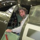
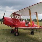
geedubelyer and 3 others reacted to Archimedes for a topic
A cache of DH82a Tiger Moth pictures of G-ANEM for use by anyone building any of the Matchbox/ICM/Silverwings kits. These, in addition to the fantastic walk around provided by Max @mozart will hopefully help anyone similarly inclined to build a Tiger! Kind regards, Paul4 points -

Make the others jealous
Tolga ULGUR and 3 others reacted to Shoggz for a topic
It's like a Russian doll! It really is packed beautifully - it looks quite a bit simpler than the Mk.XIV conversions - for pretty obvious reasons - the Mk.XII was closer to the Merlin 60 series Spitfires than the later more defined XIV and it indeed was usually a conversion from a Mk.VIII or IX in reality anyway!4 points -

*** Finished*** 1/32 Trumpeter P-47D-22 "Kansas Tornado"
Azgaron and 3 others reacted to Tolga ULGUR for a topic
Some progress Fuselage painting terminated. Next step is decalling4 points -

IBG's 1/32 PZL P-11c, Wladyslaw Gnys' plane - first allied victor of WWII
Pfuf and 2 others reacted to Thomas Lund for a topic
In my continuing different nations quest, I have come to Poland - this is IBG's sublime 1/32 PZL P-11c. I cannot say enough good about this kit, I wish they would do more... I used a mater brass gun barrels, and btw this is the only 6 gun P-11c... I accidentally dropped not one but two barrels into the wings when mounting them and they refused to come out. Replaced the gear brace PE with a thin piece of steel wire as I bent the PE numerous times handling the kit. Also added HGW seat belts from scaps from other kits. Painted with Hataka laquer paint BTW it is NOT an error that the wing upper surface national markings are not placed symmetrically. For some reason that was the way it was... On the morning of september 1st Wladyslaw Gnys shot down to german bombers for the first allied victories of WWII. However Gnys' flight leader had provided Luftwaffe their first victory just a few minutes before...3 points -
Hasegawa FW-190D "Late Version"
Azgaron and 2 others reacted to Rampenfest for a topic
Got to spraying some more today… I used one of the Uschi stencils to do a sort of mottling/pre shading. I plan on layering some other colors on top of this before the final camo colors go on. I taped off the areas that are RLM 66 for now. I then started spraying the control surfaces with RLM76 from Vallejo. You can see the subtle shading underneath bleeds through nicely. Also, as well as a few areas I need to work on the tail with regards to the left horizontal stab and my fingerprint3 points -
Academy F18D Hornet 1:32 "Night Attack"
themongoose and 2 others reacted to Mel for a topic
Today I made some progress on the landing gears and the bay doors and I also had to retouch the radar cone.3 points -
1/32 Trumpeter P-51B Mustang with Aerocraft corrections
Azgaron and 2 others reacted to Tolga ULGUR for a topic
Looks like it's ready to be painted.3 points -

Make the others jealous
Rick Griewski and 2 others reacted to Kagemusha for a topic
Kev's got a review in the works, looks like yet another superb set.3 points -
The Aircraft we would HAVE to Scratch Build Right Now
wunwinglow and 2 others reacted to Jim Barry for a topic
I live this life. So far in my “build it because they don’t make it” I’m done with the 1/24 Hawker Fury, almost done with a 1/24 Bearcat, and in progress are a Me262 1/24 and an S2F Tracker 1/24. My guess is the 262 could one day be released 1/24 but until then…. My overall lifespan goal is just 6 of these scratchbuilds. I still love kits too!3 points -
Malvinas Dagger
chrish and 2 others reacted to blackbetty for a topic
on a lighter note, the Aztec parts from Mexico came in: seat and expal bombs3 points -
Zoukei Mura Fw-190 A-4
Dpgsbody55 and 2 others reacted to Kagemusha for a topic
 3 points
 -
De Havilland
mozart and 2 others reacted to Archimedes for a topic
Poor payment for the advice thus far given Max! you have really helped me with many topics beyond Tiger Moths! Glad they are of use. Kind regards, Paul3 points -
Academy F18D Hornet 1:32 "Night Attack"
SwissFighters and 2 others reacted to Mel for a topic
Tomorrow I will touch up the front landing gear, I have screwed it up a little because of me, sometimes my level of stupidity reaches unimaginable levels3 points -
Anyone for: Or3 points
-
The next step was to protect the decals and existing paint work with a couple of heavy gloss coats: I used Alclad's Aqua Gloss, which I generally reserve for those occasions where I'm concerned that a solvent-based clear coat might affect the decals - which is the case whenever they're laser-printed, like here. I'll leave this for at least 48 hours now, before going anywhere near it with masking tape! I've also discovered some errors and omissions, some of which I also plan to attend to. The most visible one is that I got the colour of the engine pylons wrong. I assumed they'd be white like the engines themselves, but they are in fact the same light grey as the wings, so I'll be attempting to correct that, at least. Might get a chance to do a bit more work on the Welsh kit now. At least I know not to bother with the Corogard decals! Kev3 points
-
Tamiya F-16 Aggressor, Kicked Up a Notch, May 10: Clear Gloss Coat
Azgaron and 2 others reacted to chuck540z3 for a topic
March 27, 2024 Since I’m now trying to make sure my model is as accurate as possible for a Block 25 in every way possible, I found another change I need to make since this Thunderbirds kit is for a Block 32. Apparently Block 25’s only have 2 flare/chaff dispensers on either side at the rear, and don’t have the extra 2 added on the left hand side as shown below. Eliminating them was easy by gluing in the cover Part C16 plates, then filling the recesses with CA glue and sanding everything smooth. For the 2 dispensers at the back, however, this kit doesn’t have any since the Thunderbirds have cover plates on them. Thankfully I have a few spares from the Block 50 kit, which has 8 of them. This is confirmed by a pic I took of my subject in November 2022 at Nellis AFB. Note that the forward 2 dispensers are missing as they should be for a Block 25. Next, I decided to get into the ResKit F100 PW engine I bought for this build, but it doesn’t indicate if it’s the original 200 version, or the more modern 220 or 220E version. No matter, because this is the one I’m stuck with. This engine is super detailed like the ResKit J-79 engine I used on my CF-104 build, that turned out looking pretty good if I do say so myself….. Like the J-79 engine, unfortunately, the instructions just show you how to put the engine together, with absolutely no guide as to how it should fit with the kit parts. You are left to figure that out on your own, so I came up with a plan as you will see below. Like all ResKit resin, there are large casting blocks to cut off with a razor saw, which is tricky to do without damaging the fine details of the delicate parts. Here is the main nozzle part and the approximate location of the cut line on the instructions. The best way to smooth out the cut line is to rub it on a rough sponge sanding block to get off the biggest chunks. Unlike what the instructions call for, I’m sanding off the entire bottom of the nozzle, which removes a few millimeters of interior detail, in order to get a stronger fit with the kit parts as you'll see below. This small detail will not be missed once the engine assembly is assembled and painted. Here I’m using a flat sanding belt on a flat plastic holder, to keep the bottom of the nozzle as flat as possible. On the sponge sanding block, the rocking motion and flexible surface creates a rounded edge, which you don’t want for final sanding. The sanding is complete with a light buff with a 1000 grit sandpaper sponge. This is the main goal when the ResKit resin and kit parts are glued together. You want this fit to be as flat and flush as possible and it looks like the nozzle diameter is perfect. Here is the top of the flame-holder with the recess and notch, that the nozzle fits into. With the base of the nozzle sanded off, I sanded off this recess as well. In order to fit the KesKit flame-holder into the engine fairing, I glued into place a thin strip of 0.5 X 4mm styrene into the kit parts P10 and P11, which turned out to be perfect. And this is the reason for my departure from the ResKit instructions, in order to get a tight and very strong fit of the resin engine to the rear of the fuselage. With this wide and flat surface, the engine nozzle can be glued on at the end of the build easily, with no fuss with finicky recesses or notches in the resin parts, which are not as strong. Further, you can glue the “best side” of the nozzle upwards as you choose, without the need to lock it into a specific notch on the flame-holder. The last resin block I cut was across the very detailed circular grid at the front of the flame-holder. I dreaded doing this, because breaking the delicate parts seemed inevitable, but at least I had the kit Part P25 to fall back on if I made a mess. There are 4 tabs that are a bit longer than the rest that I marked with red dots, that fit into slots of the engine duct. The reason I noted the 4 longer tabs is because 3 out of the 4 broke off when I cut the assembly off the block, with the only remaining one marked with a red dot. I’m guessing it’s because they flexed more with the saw and due to the extra stress, broke more easily than the shorter tabs? At this point, I was fairly certain that I would be using Part P25 instead! Much to my surprise, I was able to cut off the extra backing from all of the tabs and glue the broken parts back on with CA glue, without any more drama. Using styrene cutters, the key to cutting the backing was to cut horizontally with the assembly to the base of the tab, which broke the vertical portion of the backing naturally, snapping it off. From there, a #11 knife was used to clean everything up. The repaired tabs are quite strong, with a fairly large amount of CA glue applied from the rear where it can’t be seen. Here it is dry fit into the base of the engine assembly. My kit came with a broken rim on this part, which isn’t a big deal because it will not be seen when fully assembled. There are 3 more brass parts that need to be added below the resin assembly. Final dry fit assembly, compared to the kit part. Pretty impressive engineering by ResKit! So now it was time to deal with how the front of the KesKit engine was going to fit into the fuselage. I had the same problem and solution with my CF-104 build, so I sort of knew already what to do. Using the front part of the kit engine that slides into a groove in the engine bay, I cut off about 1” of it and the front tabs. I then cut off two pin locks in the engine bay that normally hold the kit engine. Before I glued any engine parts together, it’s important to figure out which way is up and which way is down in the engine compartment. I looked at several pics of PW100 engine pics from the rear and came up with all sorts of angles that I found confusing, but most of them were for F-15’s which appear to have the engines installed a few degrees out from what I finally settled on, like the pic below from an actual F-16. Note the flat top to the heptagon with longer arms coming from the corners. So I set the “Top” accordingly and marked it with a pen, which coincides with the deepest tab of the resin assembly, which is no doubt there on purpose. The front portion of the kit engine I cut off was then glued to the base accordingly. The sub-assemblies indicating which portions go to the top. While the assembly on the right is glued together, the rest are only dry fit at this point. The groove at the top of the engine bay is quite long, thanks to it sharing the same part as the Block 50 kit, which has an entire engine that can be removed for display. This kit only uses the rear of the groove, which is all I need. The Engine sub-assemblies now just slide into place with ease, after trimming the side pins of the kit parts to allow clearance, while still remaining snug. This fit is solid, so once everything is glued into place, the engine will be very secure when bounced around. With fuselage Part B20 dry fit into place, the engine fairing fits fairly flush on the bottom. Same thing on the top, showing that the hole of the fairing lines up with the hole in the fuselage top perfectly. And the candle on this engine cake, the rear nozzle, which can be glued on at the end of the build with no fit issues later- and no gaps. So the current game plan is to paint and detail all of the engine parts, then install the engine with the kit fairing and other fuselage parts to ensure that everything is smooth and looks natural on the outside, which will take a little light sanding. From there, I’ll mask off the rear of the engine and attend to the other kit assemblies on the tail. One might ask why I worry so much about the interior of an engine that I'll rarely see again, even with a flashlight. The answer is, "It's Fun!", at least to me, which is a big part of what modeling is all about. Thanks for checking in. Cheers, Chuck3 points -
nearly finished - just flying wires to go.. TTFN Peter3 points
-

Harvey
Rick Griewski and one other reacted to LSP_K2 for a topic
Agreed. I always liked ol' Harv.2 points -
P-47D serial dilemma. RESOLVED!
JeepsGunsTanks and one other reacted to MikeMaben for a topic
Silly, you fergot the wings2 points -
Remember this? That was posted on Nov 21 of last year - four months ago. The finished engine cowl section - painted and all. There is still some more blue that has to be applied to this model - around the windshield, and the uppermost panels between the windshield and the firewall, which is the aft end of this sub-assembly. You will recall that I, in my impatience, just had to apply a final topcoat to the forward end of this P-51. I couldn't wait to show off the blue-noser blue. Well now it occurs to me that the paint cocktail I ended up with is not going to wait forever for me to complete the forward fuselage of this uber-complex model. It has already been four months since I shot that paint, and it will probably be something like another four months to complete the forward fuselage such that I can skin it in aluminum to match the finished engine cowl section, and paint the rest. I am screwed if the paint decides to dry up; I have no confidence I can match up a new batch to the old batch. To review, this is the combination: Tamiya medium blue XF-18 (49% plus) Vallejo medium blue 70.965 (49% plus) Vallejo white 71.001 (quite a few drops, but quantity unknown) No way would a new batch be perfect. Were it all Tamiya, I would not be stressing as much about the shelf life. But it isn't. I just don't know how long its shelf life is. So far it seems fine after four months. Am accepting comments from the master painters here who are tuning in. So I think I am going to hit the pause on the assembly plan, and try to get the rest of the blue on sooner rather than later. To do that, I have to mate up (dry fit) the engine cowl section to the forward fuselage section in its current state, and skin the forward portion of the forward fuselage section to match the already skinned engine cowl section. I do not trust using the jig to trim the fuselage section aluminum skins. In theory it would work, but in practice, I don't think I will get a great match to the engine cowl. And it needs to be good. In order to do that, I must be able to assemble the two nearly complete sides of the forward fuselage section, and the fully complete windshield surround section, without the benefit of the fuselage jig. I think I know how to do that: 1. 3D print the firewall, with its four posts that match the holes in the forward ends of the four longerons. Just like the forward end of the jig does now. My firewall is already mostly designed in Rhino. It won't take much to finish it and print it. Fit the firewall to the engine cowl and then the forward fuselage can be fit to the firewall, and taped in place. 2. Rhino design and print a mock station 200 frame, just a plate with four posts to match the holes in the aft ends of the four longerons. Again, just like the aft end of the jig does now. This part can be taped to the side panels and will stabilize the aft end of the side panels and keep them in place. 3. Rhino design and print a simple square plate with four posts that match the four wing mounting points at stations 104 L&R, and 146 L&R, on the lower longerons. Again, just like the jig does now. Tape this to the side panels also. 4. Tape the windshield onto the side panels. This should give me an accurate forward fuselage assembly that holds shape acceptably and can be fit onto the engine cowl, complete enough to skin the forward end of it, to perfectly match. Maybe skin just the windshield surround, since the blue doesn't extend down to the side panels. Once the trim is final, mask up for the remainder of the blue, paint it, and problem solved. That is if there is a problem at all. If the shelf life of my paint is alot longer than a half year, then I don't need to do this out-of-sequence work. What do you think?2 points
-
Finally, a producer whose box art reflects all the "flak" the kit will receive from potential buyers2 points
-

dH Vampire
R Palimaka and one other reacted to Mark_C for a topic
Here is one I found, Guy: It's apparently a Mk. 2, but it should still give you some ideas.2 points -
Intake was puttied and sanded smooth Painted cockpit with cushion from epoxy putty It's a big one Airbrake wells painted red like in F-142 points
-
Hellooo! Another small update. The canopy has been started, but not finished (just plonked on for these pics). The wings (top only, haven't attached lower wings yet) have been base-coated, gloss varnished and decals have been applied. They look awful at this stage, but with the addition of watercolour pencil washes, rivets, chipping and various stains, etc. they should come up OK... Hopefully. Made a start on the exhausts. Will leave them as is until later to see if I need to knock them back a bit, once the rest is done. It's coming together, but work and distractions keep getting in the way. Cheers, Kels.2 points
-
The main build is done with a rough base coat. This also fills the small gabs. From now on it all about painting.2 points