Leaderboard

Popular Content
Showing content with the highest reputation on 02/08/2021 in all areas
-
Thanks guys! Appreciate the feedback! Thank you Chuck! Very encouraging to see that others have used the Barracuda nose and the Special Hobby engine. Most of my build research was confined to Works in Progress and I forgot to check the RFI board! I'm not going to get much deeper into this build until I figure out what I want to do with the surface details. My options range from (a) do-nothing all the way to (b) sand everything away and rescribe-rivet it all over. I want to make improvements but I don't have the desire or resolve to do (b). I've tested the rivet dot pitch pattern against my riveting tools (RB Productions, Galaxy Tools, Trumpeter) and they don't match so fixing the kit rivets will have to be one at a time. I am toying with the idea of filling all of the rivets with black CA glue and punching new rivets with one of my tools. The black CA would give me the visual pattern of the rivet lines without having to re-draw them. But I don't know how the filled rivets would respond to having a rivet tool run directly over them and I'm afraid of creating a mess. And there are a TON of rivets... lots of filling and sanding. I did some preliminary dry-fitting with the major fuselage and wing components. Fit is not especially great but not horrible either. Checking the wing geometry to make sure that center section is flat. Will have to pay attention to this area as internal components are added to make sure that the fuselage doesn't push the wings out, causing an anhedral condition. Got a new tool in the mail today to deal with the big casting block. Tamiya Thin Blade Craft Saw #74024 About the size as a big kitchen knife! Plenty of blade clearance to cut through this piece. Life is so much easier with the right tools. Thank you Damian for this excellent recommendation. Make sure you wear a mask when cutting resin! One of the things I noticed after taking my first photos of the resin block (meaning it wasn't caused by the sawing process), was a broken ignition wire. That got me to thinking... what if I replaced all of the ignition wires? Very do-able!12 points
-
 Today - meeting from 8.45 to 16.30, and I'm expected to talk for one... ONE... minute8 points
 -

1/32 Special Hobby Hawker Tempest V - Fairbanks JJ+F
Paul in Napier and 7 others reacted to Thunnus for a topic
Thanks Tom! I'm most likely sticking to the marking options included with the kit but haven't made any decisions yet except it won't be a Clostermann Tempest. After the Super Bowl, I replaced the molded ignition lines on the resin engine with lead wiring.8 points -
Well, I needed a bit of a MoJo pick me up............something simple, small and that I did not have to add a lot of AM bits or resin to, so here we are with a Meng F.1. I am not putting the Tigercat down, but working on this in parallel so I don't get burned out. From what I can see and have read, this will be a great fitting little kit. I will be doing Werner Voss's F.1 103/17 as it appeared in his final valiant battle against James McCudden and 6 other aces in 'B' Flight of 56 Squadron on 23 September 1917. This will not be a super detailed or slow build (I hope) but rather a quick enjoyable one. I've got more AM than I thought, but will not be using it all. Not a TON of plastic in the box, and assembly seems straight forward Couple bits of AM I found that will all be easy to add, but I will not be using the rubber tires: Can anyone confirm this is the correct engine? Looks like it might be more detailed than the OOB Meng kit. Also will be easing paint and decaling by doing everything in a single fell swoop, with some lovely Aviatic decals. I will be doing the cowl face with some masks created on my Silhouette: They seem right on with what I can tell Voss's kite appeared like in 1917: First job up is one of the two things wrong with the Meng offering that I can see, and my kit had both; warped wings (all 3 to one degree or another) and a broken forward cockpit/cowl piece. The wings were worse off the sprue than on: Being under quarantine, and it being -15F to 5F outside lately, I've gotten into tea. Usually a coffee guy, but started having tea for a change, so while heating up some water for tea, prior to boiling it, I used that to warp the wings back into shape. Took all of about 10 min, and gave the peppermint tea a nice plastic wang. Pretty straight now, and really wasn't a huge deal. You can also see the broken part on the middle wing as well: First up for Voss's F.1 is to remove the stacking pads, fill the skid holes, and fill some of the depressions left on the leading edge sprue gates. I'm also going to be masking the leading edge off and sanding down a bit of the rib/nail detail, but not all of it. I also snipped off and cleaned up a lot of the first steps to the cockpit assembly: So far so good! Things are progressing quickly, and Im hoping this build to be very enjoyable. We shall see......... Cheers!7 points
-
still sanding and filling but im going to get there Mark7 points
-

Infinity Models SB2C-4 Helldiver update
scvrobeson and 6 others reacted to Mirek O for a topic
Hi, latest news: http://www.infinitymodels.cz/en/sb2c-4-helldiver-1-32/7 points -

1/32 HK Models Lancaster B Mk.I Nose Art Kit RF128/ QB-V Victorious Virgin.
Greg W and 6 others reacted to monthebiff for a topic
Been working on the Fraser Nash turret this weekend and I'm thinking I will call it done now and ready for painting. I have two or three areas to revisit on the interior this week which I'm not happy with or missed something but about there now. Regards. Andy7 points -
A while back I stated I would be doing some limited cockpit work and then closing it up for a long period while I did the inboard wings. Well, I am finding there is a whole lot of cockpit work that can be done before I go to the wings. Here is another cockpit update: The horizontal beam on the Sta 186 bulkhead (that I cut in half) is fragile and easily catches on things like my sleeve or a fumbling finger. So each side needed some reinforcement. The LH side was reinforced by the side console (sort of). The RH side needed something so I took a break from the LH side and did up the O2 bottle and its support stand: You can see it somewhat reinforces the beam. Hard work - almost entirely because it snugs up to the side wall and the side wall on this model is grossly out of scale due to its thick gage. A layout helped, but I can only approximate the local contour so I have to resort to a bit of trial and error with the bracketry. The bottle itself is acrylic and turned on the mini-lathe, and is something like 0.2 inch shorter than it should be to clear the aforementioned sidewall. The hardest part was the straps just due to very small details. As you can see I chose yellow for the color; some of you would probably have chosen green. Pressurized bottle colors for WW2 aircraft is an interesting subject with many opinions.... When I get to the RH side, this bottle will be plumbed to the familiar O2 regulator and its long flex hose. And then it was back to the LH side, where I will be for a good while longer. Gadgets galore! Next to the seat are two details that need to be there even if largely unseen. One is a pulley bracket support shelf, and the other is a truss/bracket structure that supports the CO2 bottles and also the hydraulic hand pump. It is a good example of a poorly designed afterthought of which the Corsair has many examples (IMO). I provide pictures from the parts catalogue to help describe. First the pulley bracket support shelf (for aileron trim cables, tail wheel lock cable, and wing hinge pin lock cable): And the CO2 bottle and hydraulic hand pump support bracket: And my versions of these details: Not perfect by any means. But once I get the bottles in there and tighten the cables (fishing wire), it should look the part. It will probably take a flashlight to see them once the cockpit is done and the seat is installed. That truss/bracket thing was a major PITA I can tell you! Lots of tweezer work on small parts, and trial & error trimming. Next post you will see the CO2 bottles and their very interesting cradles, and the hydraulic pump. Take care!6 points
-

Mig-29 A izd. 9.12 BG AirForce
Youngtiger1 and 5 others reacted to ShelbyGT500 for a topic
Well THANK YOU friends for ALL kind words and posts here I'm glad that you like the cold war soviet jet. So continue with the front part of the canopy - first polished with tamiya compounds, paint with armor-glass from alclad, and after 24 hours polished again with blue and black tamiya compounds and finished with 3M wax. And for final touch I add the front antennas at the screen. Some work on the plane itself - mounted the air intakes, vertical stabs, and all moving parts of the half-wings. And that was all for that project Unfortunately I must leave it for a few months, and start working at 32-nd scale Mig-21 UM OOB, for a gift, and it means that I've got a dead-line So thanks for stopping by here and as always - CHEERS friends.6 points -

Hasegawa F-86 Sabre
themongoose and 5 others reacted to Dragon for a topic
Update time. The bench time has been spent working on getting the wing tips and slats blended into the wing. After a lot of sanding, puttying, sanding, more puttying, and more sanding, I finally got them to my satisfaction. I'm not sure what I'm going to do about the panel lines since there is quite a bit of putty; I may try drawing them with a pencil. I need to scratch build the wing fences, but I haven't found a good pic of them yet to know what they look like or their size. I also spent time working on getting the nose cone and fuselage halves to blended better, not perfect, but since my builds are "3 footers", it'll due. I've glued the wing and fuselage together, and it's starting to look like a Sabre, still need to glue the wing roots. Next up is working on the rear deck and the canopy frame. Thanks for looking in on my build. Mike6 points -

Silver Wings Gauntlet!
scvrobeson and 4 others reacted to mozart for a topic
Wonderful! Let's hope Brexit doesn't complicate getting one here asap!! Just heard from Simon, with the discount the cost to the UK including shipping is 111 euros. Mine's ordered! By the looks of it only the three-bladed prop is supplied but I much prefer the looks of the two-bladed Watts propeller, so I think I’ll have to see what I can do about that.5 points -
- I started from the engine, removed plastic spark plugs and made new ones using Vectrocut's nuts, needle pieces (0.5mm diameter) and cooper wires - painted in black as a primer and covered with aluminium on top of it, spark plugs in white and used brow wash in the end. When everything was dry I added spark plug wires - exhaust was painted in cooper - seat doesn't look as original, firstly I thought about making a new from a plastic sheet, then just decided to drill some holes. Anyway inside a cockpit with seat-belts the difference will not be noticeable to be continued....5 points
-

Albatros W.4 - #911 'Olt.z.S. Viktor Schulz' Windau (Finished)
scvrobeson and 4 others reacted to kkarlsen for a topic
A bit over the top? Converted larger tail and elevator. Small details on the fuselage parts, I'm using the kit parts as much as possible to save some of the details. The obvious closing of one of the machinegun openings. Kent5 points -
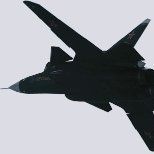
Sukhoi Su-47 Berkut 1/32
Serkan Sen and 4 others reacted to Bekim for a topic
Air intakes can be done also with covers...5 points -
back side .....5 points
-
or in closed Position.....5 points
-
Sukhoi Su-47 Berkut 1/32
Serkan Sen and 4 others reacted to Bekim for a topic
here in place with open Doors5 points -
integrated rear Weapon Bay with Wheel well ......5 points
-
The wife insists on buying pyjamas for Christmas Eve presents. Every year. I've got cupboards bursting with bloody Christmas themed pyjamas, but she won't stop. Unfortunately, I'm the camel toothed old bloke on the right. My son is doing his best elf impression. I can't wait to see what the next Christmas brings......5 points
-
Hi guys, I've been absent from the forum for a while, due to my full time job interfering...lol The SAAF operated the sleek Mirage IIID2Z, which resembles a Mirage 5B very much. When I was working on the 1/32 Cheetah D conversion set, I realized that there are quite a few shared components, and halted work on the Cheetah D to ensure that they will work between the two, so that I don't have to go through this again. Most of the work is done on the IIID2Z, and it's down to more sanding, scribing and refinement of the parts. Still have to make the arrestor hook that fits in the slot of the narrower ventral fairing. The decal sheet has also been printed. Rough test fit earlier this week of the forward fuselage with the nose cone. Cheers, John4 points
-

1:32 Gloster Gauntlet MkII
reconspit and 3 others reacted to Silver Wings for a topic
We are excited to announce that our first kit for 2021 is the 1/32 Gloster Gauntlet Mk II. The master and prototype have already been completed and production begins shortly. We anticipate the kit to be available for purchase in March 2021. The kit will be offered in three colourful options, with decals for the following aircraft: - Gloster Gauntlet Mk II of 74 Squadron RAF , Horn church, 1937 - Gloster Gauntlet Mk II ‘44’ of the 112 Squadron RAF, Helwan, Egypt, 1940 - Gloster Gauntlet Mk II of T-LLv 35, Utti Heinakuu, Finnish Air Force, 1942 Kit includes: - 101 resin parts - 2 film elements - sheet - 23 PE parts - sheet - reinforced: wings, landing gear and struts As a special thank you, all direct orders placed in February 2021 we will be offering the Gloster Gauntlet kit in the time-limited offer of 15% discount off its standard price. For a detailed calculation including shipping cost, please write us at silverwings@silverwings.pl. Sincerely, The Silver Wings Team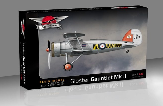 4 points
 -

new modern USAF seated pilot by reedoak
A-10LOADER and 3 others reacted to norbert for a topic
Hello ! here is reedoak first USAF modern fighter pilot : F-16 pilot, sitting, with survival vest, JHMCS helmet, pistol in holster, and without life preserver. typical for combat flights over dry aeras. have a nice day ! Norbert4 points -
I was doing some research on my new WIP and came across this. This to me is SO cool, to see that many full scale DR.1s in flight, and from the same Jasta (11) with the Baron and his scarf to boot. The landing sequence starting around 3:50 is really quite something. Knowing how badly these things can turn on a pilot during landing/take-off, these reproduction pilots really know their stuff. Enjoy!4 points
-

IBG Models - 1:32 PZL P.11c Test Build
Landrotten Highlander and 3 others reacted to Trak-Tor for a topic
www.facebook.com/ibgmodels And they have listed this: 32002 – 1/32 – PZL P.11c Fighter in Romanian Service on their web site already. Juraj4 points -
I've circled back around to this Electra build, and decided it was time for a heavy coat of primer, followed by some remedial sanding, ready for the next round of filler: My primer of choice in this instance is Tamiya's Fine Grey Surface Primer, straight out of the can. This revealed issues everywhere, but it wasn't as bad as I expected to be honest. The worst spot is where the rear wings join the fuselage at the bottom, which will need more than sanding to fix. But that's for another update! Kev4 points
-
I dont think that is what anyone is saying honestly. I've got plenty of Meng kits, including their 163, but none of that really has to do with what I was talking about at least, and I have to assume the same for some of the others. The statement about Meng having 0 experience had 0 to do with tooling or their ability to tool anything. It also has 0 to do with Meng being a Chinese company. In order to get a decently accurate DR.1, up to the standards of WnW, the research would have to come up to their standard, and that they likely would have needed help with, specifically from WnW preferably, as Sir Peter was passionate about WW1 aircraft and his research team is second to none. This would have been a very VERY different kit if it was a Meng only kit from design to finished product, not because of any other reason than they have little to no experience with WWI aircraft or research there of. Having a discussion about a company and its merits is fine, and having differing opinions on them is fine. However, Im going to suggest right here and now that we all make sure this thread stays about the topic and hand and doesn't take any stray detours into anything personal with another member(s). That's all Im going to say about that.4 points
-
Hey we were here all along! We'll be cool and popular! No that doesn't sound right. Never mind. Dan4 points
-
Okay, I'm gonna spin up another build. I purchased this one quite a while ago but after admiring the contents of the box after receipt, it went up on my shelf and has stayed there ever since. It is not a subject that I am very familiar with but I started to think that, as a counterpart and worthy adversary to the Dora, it would be good for me to stick my toe on the other side of the fence. It will be tough following the bar set by Chuck540z3 so please notch down your expectations accordingly. I will be referring to Chuck's build along with others that have come before and hopefully add my own things here and there. The Hawker Tempest, like the Typhoon before it, was a brute of an aircraft, which is befitting of its immensely powerful 24-cylinder liquid cooled Napier Sabre powerplant. It is this powerplant that sets the Hi Tech version apart from the standard release. Although I took the photos for it, I don't think I'll do a full sprue tour of this kit. There are plenty of online reviews that highlight the kit contents better than I so I'll simply you to Iain's wonderful review posted here at LSP if you are interested in a walk through. https://www.largescaleplanes.com/reviews/review.php?rid=1928 A few notes about the kit plastic... the exterior of the Tempest is fully riveted. I don't know if I'm happy about that or not. Although I like my builds to be riveted, I don't necessarily like it when the rivets come as part of the molding. The rivets made manually using a circular rivet tool produce very fine holes and result in an effect that is subtle and not distracting. Molded rivets are commonly too large and only a few companies can produce rivet detail that I think is great right out of the box (Tamiya and Eduard for example). Based on my initial observations, the riveting is good in some areas and inconsistent in others. The dot pitch of the rivets does not align with either the RB Productions Rivet-R nor the Galaxy Tools rivet tool so any repair option is going to be manually intensive. Outside of the rivets, the molding quality on this kit looks very good. One of the places that manufacturers commonly sacrifice on mold definition is the interior side of the fuselage, wings and landing gear covers. Special Hobby has done an excellent job of not skimping in these areas. I like how Special Hobby treated the fabric-covered control surfaces.. the stitching detail isn't overly exaggerated. Given the amount of included resin and photoetch, it is somewhat surprising that Special Hobby does not give the modeler a choice when it comes to the instrument panel. But, it looks like a good result can be obtained by using the plastic instrument panels with the instrument faces represented by decals. The clear parts exhibit some scratching (maybe not the manufacturer's fault since I bought this kit secondhand) and some distortion as well. I can fix the scratches but not the distortion, unfortunately. Back to that Napier Sabre engine... the highlight of the kit for me is the beautiful representation of the Napier Sabre engine in resin. The resin components come in their own little box. Inside the box, I found four separate baggies of resin parts, including this bad boy... It is not a complete engine but nevertheless an impressive representation of the upper half of the Napier Sabre from the exhaust stacks on up. I don't normally like to model my aircraft with open panels but I'm going to make an exception for this one. This resin is just too beautiful to ignore. Here are the contents of the next baggie full of resin. I'm not familiar with all of the parts yet but I think this bag contains mostly engine components including impressively long and complex lengths of hydraulic tubing. I believe the small block in the front are the four gun barrel tips. This next bag contains some exterior components like the engine cover panels and resin versions of the wheels and pilot seat. Although the cover panels are very thin, I don't think they are meant to placed over the engine, which is actually fine by me. The last baggy holds mostly cockpit components, by the look of it. I see foot pedals, a couple of different gun sights, the handle for the control stick, among other things. There has been breakage of a few delicate parts but nothing that will be noticeable or significant, I don't think.3 points
-
That's the right engine. For the rigging, I would try finding WNW's detail pictures of the Dr.1. I think the only exterior rigging is cross bracing of the landing gear and the upper wing, and the aileron wires going from the fuse to the upper wing. Interior rigging would be cross bracing of the fuse sides. 'Check your references'3 points
-

Spitfire Mk VIII
MikeC and 2 others reacted to Dpgsbody55 for a topic
Thanks Alex. I'm liking your Mustang build. Building these V-12 ignition harnesses is not at all easy, and made harder as you get more ancient and have to squint more at these things. But they add so much to a model and look heaps better than the rather 2 dimensional etch jobs. So my Spitfire build continues with the engine firewall and mounts, as well as some more detail on the engine itself. Here's the firewall with some plumbing added. Next up, after a little tidy up, was to add the engine mounts, and a little more etch detail. Then I started on the pipework provided in the kit, starting with the oil system. This is a bit of a pfaff to put in as it involves two pipes and the oil filler can which has to be mounted so that the aforesaid pipes can be attached. I did this all in one go, which I think is the best way to get it right. I let this dry before adding the other three pipes. Once that was dry, I added some more pipes, as well as the rear brace for the engine mount. I still have a few more pipes to add, but I can't do that until the engine is added permanently. I next added a little of the linkages at the rear of the engine. These were built from plastic sheet stock and 0.4mm wire. More squinting . So a few hours ago, I added the engine to the firewall/engine mount assembly. As I said, I have a few more pipes to add to this, the oil tank etc, as well as some touch up work to do first of all. Next up after that will be to complete this assembly with the cowling mounts, but I'll leave the exhausts of those mounts until I get to the final stage after painting. I won't be adding the air intake below the carbie as I'll display this with the bottom cowl permanently in place. But to give myself a little inspiration, here it is placed, but not glued, on the plane. I used the top cowl to check alignment and at this stage, I'm happy with that. So a bit more engine work, then back to the model itself so I can get it to a point at which I can apply some paint. I don't think I'll be displaying it on the stand as it's pilot-less, but I did build up the stand to see what it might look like anyway. Until the next update. Cheers, Michael3 points -
Seven Jasta 11 Dreideckers
Alain Gadbois and 2 others reacted to Out2gtcha for a topic
Probably radials as they have an actual throttle, and are much easier to fly Im sure. Here is a German Tripe with an actual Oberursel II repro. Having that "on\off" type throttle would have been a pain to fly:3 points -

Bodenplatte duel build Spitfire IXc vs Fw 190 A-8
themongoose and 2 others reacted to Wackyracer for a topic
Both builds primed and heading to paint. Changed the 190 scheme though. Just really like the red white red band on jg6 and found rote 12 was shot down and pilot captured on 1st Jan 1945. Pic is just for reference. Theres very few photos that show the defence band let alone profiles but Bodenplatte book lists the aircraft and their fate so could find a plane with a similar outcome as the Polish spitfire.3 points -
Thanks Antonio! That Dora has seen better days! Is that the wreck from Lake Schwerin? Here's the seat with the HGW harnesses attached to it. The seat is then slid into place along the seat rails. I added an oxygen tube per the Eagle Editions instructions. Here we go with the cockpit disappearing act. The starboard sidewall, the forward roof and the rear deck are attached the box-like cockpit is complete. We dry-fit the cockpit tub into the fuselage to make sure that it sits properly. As you can see, the view into cockpit is VERY limited and the addition of the canopy parts will make it even more so. With the cockpit complete, we can now focus some more attention on the rear engine area.3 points
-
HH-60G Pavehawk Kitty Hawk 1/35 DONE!!
KiwiZac and 2 others reacted to Hawkwrench for a topic
If it's not too late, you oughta remove the metal nuts and just use your rivet decals. Their are no bolts there in the paddles. Tim3 points -

Delta Dart
Rockie Yarwood and 2 others reacted to Dandiego for a topic
More basic construction. Exhaust assembly. Painted and with the interior parts added. End plug with slot added to glue into the keel. Additional tail support. A popsicle stick. Kit intake with a second layer of plastic to add strength. Interior of fuselage/intake area with additional plastic sheet glued in for rigidity. Iteration 3 of the weapons bay. I have added many internal details to the 3d print. Main landing gear bay. Dan3 points -
I'm quicker than some, slower than most... I think. And I like having two projects going. It allows me to have something to work on when I'm in the paint drying or otherwise waiting phase. I can also shut down one build to concentrate on the other when I get to certain phases or moods. Gonna jump right into the deep end with this one! The engine! I have some thoughts and preliminary ideas about the engine but I think the most critical thing is how the engine fits into the fuselage. And there is no way to do that until we make the necessary cuts. So... With the nose halves taped together, I've drawn the cut line just above where it should be to give me room to trim neatly down to the actual line of demarcation. Razor saw made pretty quick work of the required surgery. You can see the panel line just below my cut line that I'll eventually have to get to. The ironing board-shaped casting block extends along the entire bottom. I don't have the necessary cutting tools to deal with such a large block but cutting the tip off the ironing board was enough for preliminary testing. With the front tip of the casting block removed, and some minor shaving of the fuselage interior right at the front, the engine block seems to slip into position pretty well. I've not attempted fitting the radiator intake parts but I'm going to assume that removal of the engine casting block will be necessary for those parts to fit. I performed this surgery right away to help answer a question that I have in the back of my mind: Do I consider using the Barracuda corrected cowling and spinner? How will the reduced diameter of the spinner and fuselage section at the forward end impact the placement of resin engine? Is it worth an attempt? At this point, my mind is saying no, don't bother but I'm going to sleep on it.3 points
-
So where am I? To review, I am trying to get as much done in the cockpit as I can before the bottom must be joined to the sides. The bottom, as I have stated before, is the wing center section. Sooooo, if I am to join that to the fuselage in order to complete the cockpit, the center wing itself must be completed - a huge job (LG bays, and the wing fold if I choose to try it). A sequencing nightmare of sorts. So I have been concentrating on the LH side of the upper cockpit for quite a while now, and I have some progress to show you. Last post I said that the Sta 186 bulkhead (seat and armor plate bulkhead) needed to be there in order to stabilize the side console. Here is the bulkhead, already fabricated and installed into the fuselage, including the horizontal beam that the seat and armor plate attach to: You can see the fittings for the seat frame attach. Also note the chord flanges protruding aft in that first shot. That will aid in joining the aft fuselage when the time comes. So I glued the horizontal beam to both bulkhead halves after gluing each half to its respective fuselage half. This assured a good level orientation. Fabbing the bulkhead details to closely match the inner contour was no easy thing. As is usually the case, laying it out took more time than making it. All the parts you see are of course made from plastic sheet or rod or angle stock. But now, I had to disassemble the fuselage again. To do this I cruelly snipped the horizontal beam in two: I will join the two beam halves back down the road. It won't be visible at all - it will be behind the armor plate. Now to get back to work on the LH side. It was time to get in some more bracketry, and then finally the aux panel and side console. Voila: On top, you see the canopy rail structure, all finished up with its support fittings at each frame, and the detent plate lying on top. This allowed the canopy to be slid back to any of several partially open positions. Just below that is the engine control quadrant mounting bracket, with the horizontal bend in it. The quadrant itself is coming soon. And below that of course is the freshly installed LH side console and all its gadgets. Forward of the side console is the LH aux panel, also freshly installed. Time to see what this cockpit is starting to look like: There is SO MUCH MORE TO BE DONE! Stick with me - it's going to be a long and interesting journey. So far so good.3 points
-
 Hey Bill, the answer to this question depends on a few things. Presuming the base coat you are shooting is acrylic and the washes you are using are oil or enamel-based (or even water-based), then strictly speaking you don't need a varnish coat. However, if your basecoat finish is matt or satin, the wash will "grab" a bit all over rather than just staying in the recesses. This is not necessarily a bad thing if you want the wash to also function as a bit of a filter and dirty things up a bit - you can manipulate it with a q-tip or such moistened with thinners for a pleasing result. However, if you want the wash only in the recesses then it is advisable to seal with an acrylic gloss coat. Looking forward to the build!3 points
 -

Special Hobby Fieseler Fi 103R / V-1 Reichenberg
Rockie Yarwood and one other reacted to ericg for a topic
This is the Special Hobby kit, Built Out of Box. Gunze Sangyo paints used.2 points -
Cheers Tom, ive build the gear but not painted it yet, so its not an issue2 points
-

Scale model resurgence
scvrobeson and one other reacted to Oldbaldguy for a topic
It’s that circle of life thing.2 points -

Proper Bags - a new Proper Plane products!
Jan_G and one other reacted to Proper Plane for a topic
And another 5 types:2 points -
Let's get to know each other a little better. Show a photo of your
R Palimaka and one other reacted to MikeC for a topic
I managed twice, Shuttleworth and Gransden. Wonderful sight and sound.2 points -
I’m a sucker for the 74 sqn tiger tail!2 points
-

Dragon / CE 109D ... nearing the finish line ...
Troy Molitor and one other reacted to MikeMaben for a topic
Thanks Brian , the colors are a little different in real life, hope to have better pix at the finish line. Glad you got a kick out of it Troy , however , me and 'ingenious' don't really don't go together well. It just popped into my head one day.2 points -

Don't Look now.... a new 1/24 scale Fokker Dr.I
quang and one other reacted to Darren Howie for a topic
Some guys posting here might want to go take a look at the very very long list of kits Meng has in their catalogue. Anyone thinking Meng “needs” WW information to release a kit is oblivious to the obvious. DId WW help with the Me163? Did WW help with the Me410? The M-1? The Bradley? The mentality thats very obvious here from many posts is that somehow a Chinese company cant do work of there own is blatant and clear ie without help they cant do it. Oh did WW help with the F-35, Jagdpanther, King Tiger, D-9, M911 etc etc. Meng are very capable of tooling anything they want and based off the line of excellent armour kits and the aircraft they have released and have made that very clear. If you think Meng cant tool something go look through their catalogue. http://www.meng-model.com/en/ .2 points -

1/32 P-51B conversion from Revell 1/32 P-51D early
Derek B and one other reacted to ironman1945 for a topic
Hey Mark. Thanks very much. For 1/32 canopies I use ,03 inch K & S engineering PETG - Polyethylene Terephthalate Copolymer sheets. I have a stock I bought years ago from a hobby shop. Its the same company that manufactures much of the brass and aluminum rod/tubing you find in hobby shops. I've found clear styrene doesn't work near as well.. or at least, I prefer PETG. PETG doesn't bubble near as easily as styrene when overheated and doesn't scratch as easily. Hope that helps! Thanks. It has to be James Howard's " Ding Hao". First built an example of her in 1/48 when I was 13-14, using the old Monogram kit. Always wanted to build one in 32! Thanks Steve! Working time for CA/Talc depends on ratios used. I usually mix around 3-4 Talc to 1 CA.... but that's a rough estimation, which gives about 3 to 5 minutes working time. Great thing is its cheap. Also, more talc = less hardness and vice versa. Recommend you try filling the joint between 2 scrap pieces of plastic to get an idea of working time and hardness. And yes, I have no doubt as soon as I finish this project, within 1 month a new 1/32 kit will come out! So..... your welcome everyone! Cheers, hope everyone has a great SuperBowl Sunday ... I predict it will be the first SB to go to OT....Go Chiefs!..... and stay safe out there! Dave/Ironman19452 points -

USMC AH-1Z ... NOT a shark mouth ;-) FINISHED
RALPHY ROCHA and one other reacted to themongoose for a topic
She is all done and looking like she threw down some ordnance! I used the Flying Leathernecks decals, so many to choose from. I decided on the Red Skeleton Jolly Roger of VMM-163. I picked up the Werner Wings decal for all the stencils. And of course you have to use some of the kit decals as well. I will say they go on swell and were thin and easy to apply. I ended up buying Eduard seatbelts to really match everything else done in the cockpit. Since i was spending money on shipping why not get more right, so i picked up DefModels 20mm gun barrels as well :-) And with my jolly roger choice I needed some full motion video which I got from Shapeways. The cockpit additions are all scratch built. My favorite add is the tiny wound cable behind the gunner’s seat. Lot’s to see in this one. All the plastic behind the PE vents was cut away and wiring and components were added. Hard to see with my camera skills tho but I did my best to show something ;-) The 4 sensors(i assume) on the corners are hand painted and filled with testors window maker to try and simulate the glass. The pitot is brass tubing bent and sanded to shape. The seal where the stub wing meets the fuselage was painted and then coated wi5 mask solution so upon final painting it could be uncovered for a little added detail. And lastly some inspiration from a local buddy of mine, goes by Bradley25mm over on the IPMS forum - fine detailing the tail rotor gear assembly with wiring, sensors, and wire clips. His looks awesome and he gave me lots of pointers on this build. Paint was my usual mix with 1 addition this time. Thanks to Starfighter for the recommendation on color choices for the upper bluish gray on these birds. I ended up with Mission Models as they were available locally. Primer is Citadel Chaos Black (satin). Color coats are Mission Model and MCW acrylic lacquer. Cockpit is all done in Vallejo colors. Weathering is all Flory Models washes. And the final flat clear is MCW to close it out. I’ve been looking forward to this model for some time and am excited to show these pics. Once I have the base done she’ll make her way over to the RFI section Edit, can you believe I forgot one of the belly?2 points -
Thanks Brian! Some work on the cockpit before I start putting the components together. Here is the Revi 16B gun sight that came with the Eagle Editions resin set. I highlighted one of the glass pieces with clear blue/green around the edges and tinted the other one with Tamiya Smoke. The port sidewall has been glued onto the cockpit tub. After this, the throttle and the and lower instrument panel were glued into place. The foot pedals have been painted and mounted. The roof piece that the foot pedals hang down from has not been painted at all since it will be completely obscured. The seat will receive its harnesses after I've completed assembling them.2 points
-
Well - a bit of a milestone. The very complicated side console (LH side) is done, as well as the LH side auxiliary instrument panel. Many many "doo-dads" had to be created. Nothing too fancy; just using rod and strip, measuring, trimming, filing, sanding, drilling, painting - all under heavy magnification. An example (two gun charging cylinders, a landing gear control quadrant, and a hydraulic valve that mounts underneath the side console: Here is the LH side aux instrument panel which will soon be installed. I have identified the features: And the LH side console: My gosh I thought I'd NEVER finish these things. So much to it! There are three versions of the console - one for the birdcage Corsairs, one for the earlier -1A's, and one for the late 1A's and D's. My aircraft gets the middle one, and the assembly and installation drawing was too faint to be read. But the equivalent drawings for the early and the late versions were much better. So I had to do a heckuva lot of research with the part catalogue and photos to come up with the right stuff. For instance, that silver bomb release quadrant is a government issue unit used on the -1's and early -1A's, but was replaced by a Vought designed unit on the later models. Similar configuration difficulties with the aux panel. Here is a shot of both components roughly positioned: It's going to be just fine. Don't you worry! Oh BTW - I am very happy with my decal sheets from BareMetalFoil. They behave pretty darned well for inkjet decals. I have decided that the best way to go forward from here is to make the Sta 186 bulkhead, which is the bulkhead the seat and armor plate is attached to, and which is the aft closeout for the cockpit. I will split it in half - a LH half and a RH half. Take care; I'll post soon.2 points