Leaderboard
Popular Content
Showing content with the highest reputation on 04/20/2022 in all areas
-

1/32 - F/A-18C (Academy) - VFA-86 Sidewinders "CAG"
Loach Driver and 18 others reacted to Zola25 for a topic
Hi All This is the Academy 1/32 F/A-18C from the Kinetic boxing. Its been on my bench on/off for quite some time but I have managed to finish it. There are no decals in 1/32 for this aircraft that I fell in love with so I had to make paint masks for most of them, using what I could find as templates. Some stencils I could source from various aftermarket sheets but the black/orange combination is not easy to find. Its a really great kit and I am glad that Academy have re-released it again in the shape of the F/A-18A+ kit (it has all the parts for the C version). The lines of the legacy Hornets are just more appealing than the Super Hornet to my eyes.. It has the Aires Wheel bays and bombs are from Wolfpack. The Sidewinders are from Zacto models (it had to be the best for a Sidewinders bird ) Hope you like it. Niels19 points -
Thank you Andy and Kevin! Do you ever feel like you added just one too man aftermarket items to a build? Lots of issues have started to pop up. Nothing huge but they're starting to take their toll! I took a big step and cut off the kit lower flaps to make way for the brass replacements. Surprisingly, I was able to do it and keep the existing flaps intact! After cutting the starboard side flaps off, I wanted to test the fit of the brass upper wing section and found I cut off a wee bit too much plastic. Not really fault because I simply followed the panel lines. Well, maybe my fault... I think the Eduard instructions were warning me to leave a bit more plastic but I wasn't paying attention. So I added a shim of sheet plastic and that seemed to work ok. I made the correct cut on the port side. However, it was difficult to get the port upper flap into place without a slight kink. See how the middle section droops a little lower than the ends? I decided to separate the upper flaps into two sections like the lower flaps. Once I was satisfied that the upper flaps would fit, I decided to glue the wheel walls into place. As Chuck540Z3 and others have pointed out, it is much easier to glue the walls into the upper wing instead of the lower wing. My copy of the instructions have already been corrected and the long front walls (H21 and H33) are correctly labelled (I think!). The parts have been pre-drilled for wiring and numbered so I could keep track of them after cutting them off the sprue. Like Chuck540Z3, I glued a couple of parts first and checked the fit by putting on the lower wings and made sure the walls fell into the correct grooves. I started with H21+J13 and H33+J14 since they seemed to have the most positive location aids. While the glue dried, I was able to slightly push and adjust the pieces so that the lower wing fit onto the upper wings. Curiously, I was able to fit the fuselage into place without having to sand either the cockpit cage or the wheel wells. However, that positive result may have come at the cost of issues elsewhere. One is the starboard wing. Snapping the upper wing into the lower wing and positively engaging the top walls of the wheels into all of the recesses of the upper wing shifts that upper wing slightly outward. The weird thing is that the wing root joint is pretty good despite this shift. But the wing cannon openings are now offset. The port side upper and lower wing fit ok but the wing root gap is bigger on this side. I'll have to take a closer look to see if I can rectify this situation without ripping the starboard wheel well apart. I slide the nose on just for kicks. Like I said, the fuselage slide into place onto the wings without having to make any sanding adjustments. It looks like the neutral dihedral of the bottom of the wing has been preserved and I don't see any indication that the cockpit is forcing the wings apart. Yes, the nose is a bit askew but it is just resting there without any tape. If this is an issue later on, I may be binning this one! The shims that I added to the fuselage, which also serve as a rest for the engine block, maybe a tad too high but that's an easy adjustment to make. The fit on the bottom looks serviceable.18 points
-
1:18 21st Century P-51D Conversion to "B" Model With Metal Finish
KUROK and 17 others reacted to patricksparks for a topic
Finally totally finished the left side console, the last item was the bomb release control at the front end of the console just in front of the instrument panel, also added the throttle push rods... I started working on the right side of the cockpit, I didn't realize how many variations of equipment there are on B/C model Mustangs, I kept finding war time photos from manuals and factory images, many options...Anytime different radio equipment was installed it seems that different modules mounted on the right side wall... The large black panel with the toggle switches on it is similar on many ,but not always exactly the same layout... I took off today from the right wall and built the floor, Steve at "Model Monkey" was nice enough to enlarge his 3D printed 1:24 scale P-51 rudder pedals into 1:18 scale, they look great. I added the rudder cable and mounts with springs to the lower outside corners of the pedals, also I added springs to the inside sides of the pedals as I saw them on a photo of a full size restoration, I don't know if they will be visible once the center console is added though... I added birch veneer to the floor the same as "AIRSCALE" did on his "LOPE'S HOPE" , I brushed some clear lacquer on it and then some water based black with a brush and let it start drying and "stippled" it with a stiff brush to create some texture to look like anti-slip coating and then used a coarse sanding stick to "wear" it some, added some photo-etched screw heads into the panels... The rudder cable on the left side is cut off short as the cable on the real aircraft runs through/under the left console body...18 points -
1/32 F-16C (Tamiya) - Venom - Viper Demo Team
Quinta Studio and 12 others reacted to Zola25 for a topic
Hi All This is the Tamiya 1/32 F-16C in the colors of the VENOM - Viper Demo Team. I don´t often do demo schemes but this one was just too good to pass up I used quite a few extra bits; Aires Wheelbay + additional wiring Aires Exhaust Quinta Studios Cockpit Kopecky LAU 129 wingtip rails Model Maker Decal & Paint Mask set Bandit Resin Factory Travel Pod The Aires Wheelbay is a drop-in fit and essential for any F-16 build in my opinion. Its inexpensive and is almost an exact replica of the real thing. Just amazing! I wanted to try out the Quinta Studios Cockpit resin decals. At first I was a bit underwhelmed as with the colored PE. Looks good in pictures but...mjah. The trick is to give it a layer of flat varnish. It just changes everything and enhances all the details. Makes it look very realistic. Judge for yourselves - I combined it with a few details of my own and some careful brush painting. As the Venom Demo Viper never flies with anything on the wingtips, the new empty LAU-129 Rails from Kopecky Models came out at just the right time - The detail just blew my mind - take a look at his stuff - its just incredible. The Paint Mask set is really nice. I was very concerned that the emblem on the tail would curl up on itself but it turned out to be very rigid and could even be moved around just holding it with a pair of pliers. It just looks really cool painted on. The decals are extremely thin and prone to curling in on themselves though - I had to order a second set to finish the build Take a look - Hope you like it (If you click the images they will open in a bigger version) Thanks for looking Niels13 points -

OK, I'm sold!
kalashnikov-47 and 12 others reacted to europapete for a topic
Just received my very first order of AIMS detail sets from Hannants. Must give a shout out to Pastor John and his sets. AWESOME!!! I ordered the full kit for the ICM Gladiator, and was pleasantly surprised at the quality if the sets AND!!! the instructions, which include detail photo's ala WNW's. If you have ever hesitated buying an AIMS product, just buy it, you will not be dissapointed from what I have just seen. Regards, Pete in RI.13 points -

1/32 Trumpeter SU-27UB
Loach Driver and 9 others reacted to miketippingmodels for a topic
Just finished the Trumpeter 1/32 SU-27UB , its the 2nd time I have built this in this camouflage pattern, it doesn't get any easier. So its an OTB build, the only extras are the static discharge’s, and Quinta studios cockpit decals, I also used Foxbot masking , but as a template then cut mine out of Tamiya masking sheets, and HATAKA acrylic paints enjoy. Mike10 points -

SH / ICM AH-1G early cobra in 1/32(we got personality now)
matt_1185 and 9 others reacted to oppenheimer for a topic
The cobra now have some personality, mos of the paint job on the fuselage is done, next will come the other parts and the rest of the decals10 points -

MiG-23 MF TRUMPETER
thierry laurent and 8 others reacted to IrekM1 for a topic
Well, another step on the way to the end of the etażerka - it consists of 151 elements plus 5 elements base on which it is mounted. This element is part of the SZAFIR 23 radar station with the ASP-23D airborne sight - A team used to detect and target air and ground targets. Oryginal elements photos of elemet after painting inside of luk etażeka real photo model empty with my element9 points -
Thanks for the input Jeroen! getting the contrast "right" seemed to be the challenge and in the end the pure XF-24 looked way too dark. With a 2:1 mixture of Gunze H-57 and XF-24, which looked way too light in the jar, but turned out quite to my liking in the end. Please ignore the improper wihite balance in the photo above. The wings reflect the last bits of sunlight from the window, while the fuselage is illuminated from my desk lamp.. Again I went for a nonunifom finish since the contrast between white and dark gull grey is quite heavy: Add the stars and bars with the red outline and it looks quite uniform to the camera's eye And one clos up just because I love how the insignia turned out on the wings: On the fuselage some alignment issues make a respray of the ANA 621 necessary (forgot to adjust the exposure in Lightroom for this photo ): Getting the vinyl down on the curved fueslage with the kink at the spine was quite a struggle since the masks were a little too stiff to go on without wrinkles. Adding cuts eased the problem but I will consider doing this differently next time.9 points
-

****Finished**** 1/32 Great Wall Hobby - P-40 Curtiss Hawk "Flying Tigers"
Uncarina and 7 others reacted to Tolga ULGUR for a topic
Hi again A small correction on the ventral area and after few painting touches, it is ready for gloss clear.8 points -
Done with the camouflage work. I gotta agree with Bill on this one...that kinda kicked my butt, but I'm happy with it. Next...Invasion stripes8 points
-
I've been putting off dealing with the wheel wells for a long time. Just wasn't up for the tedious work of adding all the details that Tamiya left out. Also had a hard time finding good reference shots of the nose landing gear bay. Thankfully, a kind gent over on FB came to my rescue with some fantastic personal pictures. Here's one that shows how "busy" the real thing was. Note - the red cover on the sidewall with the thumbscrews was to cover the opening for an avionics air conditioning hose. Those old electronics needed a great deal of cooling and if the A/C was on the ground, with the motors off and the avionics powered up, you had about 5 minutes to get some cold air to them or you'd end up doing some damage. Picture and info courtesy of Scott Wilson, a great guy who worked on USAF Phantoms back in the day. Here is my humble attempt at replicating the nose gear bay. Everything is scratchbuilt. I used a couple of diameters of lead wire (as mentioned, this stuff is great to work with, so much more pliable than copper or stretched sprue), scrap PE for the air conditioning inlet cover and tiny bits of sprue that a crushed one end of with some pliers to replicate the wingnut screws holding the cover in place. Note that as with most of my stuff, this is still a work in progress. It will look "busier" once the landing gear is installed. Once the gear is in, I'll go back and add more hydraulic lines (the black hoses can see in the picture above, plus some more white lines as well). It's not even close to being accurate but I'm just hoping to get a general feel for how cluttered this area was on the real thing. That's it for now, thanks for checking in guys!7 points
-

WNW Sopwith Pup RNAS
Rockie Yarwood and 5 others reacted to docdodj01 for a topic
Built up the landing strut subassembly, dry fitting it to keep the alignment of the struts6 points -
Some detail painting on the pulley on the wings6 points
-
Painted the parts, and started to divide into different subassemblies Engine built and painted6 points
-
Thanks guys! And yes Chuck, I totally agree that no two builds of this kit will turn out exactly the same given the inexact tolerances in the fit of the parts, especially the house of cards type of assembly like the wheel well walls. In my case, the fit of the fuselage/cockpit does not seem to result in the outward pushing of the wing tops, even if the upper wings are aligned so that the cannon holes are matched... there are gaps at the wing root that could accommodate this shift. I'll be honest... thoughts of shelving this project have entered my mind. The wheel well issue, having to cut one of the flaps in two to make it fit, questions of how I'm going to attach the nose to the fuselage, wing root gaps, etc started taking its toll on my psyche. So last night before going to bed, I started trying to physically push the wheel well assembly into a position that allowed the wing halves to go together correctly. Kept pushing and pushing until.... yep... snap! Glue bond broke on one of the pieces. So... I wriggled loose ALL of the starboard wheel well parts, cleaned them up a tad and glued them in again, keeping in mind that I needed to slightly shift everything towards the wing tips. Here's what the wheel wells look like now... no visible change but starboard well has been dismantled and reassembled. And a look at the front showing the cannon openings lining up much better now. The starboard wing still shows a slight misalignment but I think it can be addressed at the gluing stage without an issue. With the nose attached, there are some probable gaps that will need to be addressed but look fairly manageable. It's still a ways off but I'm thinking about the resin engine. It is supposed to be attached to a bulkhead first but I am thinking about possibly gluing the bulkhead into the fuselage and plopping in the engine afterwards. This could possible ease painting but I would need to figure out a way that the engine can be securely attached in the right position.5 points
-
WNW Sopwith Pup RNAS
Bobs Buckles and 4 others reacted to docdodj01 for a topic
On with the build. Since based on dry fitting, the cockpit, fuselage and lower wing should align itself without any effort, so I glued the fuselage and cockpit subassembly Also, if you plan to build the trainer or the RNAS carrier trial pup with lewis guns, obviously you won't install the vickers gun. But they don't clearly indicate in the images of the build to leave out the ammo container for the vickers. They mention it in passing, but can be easily missed since we usually follow the pictures to check our progress.5 points -
Before the build, I of course researched on how the kit goes, and the report was the cockpit parts, when mated to the fuselage then mated to the wings, will cause alignment issues, in which the fuselage won't fit flush with the wing bottom, and that you have to shave of or and the cockpit floor. After doing some dry fitting, I found a solution: The cockpit floor, has circular notches at the bottom: That fits on the lower wings, which has the circular pegs: If you actually fit the cockpit parts, WITHOUT trapping it in the fuselage first, the cockpit floor sits flush over the wing bottom. It seems that the trouble stems partly when you glue in the curved spars on the cockpit sides that causes the problem, since mounting the part misaligned even by a few millimeters, will cause fit issues. There are 2 solutions: either mount the cockpit subassembly to the wing, then build the fuselage around it (which may add to effort in painting the kit later, OR Glue the cockpit subassembly to the fuselage half at the rear locating part CAREFULLY. Then dry fit this fuselage/cockpit subassembly on the lower wings. Once the fuselage half and the cockpit has been solidly mated, you can remove this subassembly from the lower wing, and then glue the other half of the fuselage to close everything up Note at this point, I haven't glued the fuse together, and only held in place with tape But you can already see that the fit is flush and exact. One way to check it is look inside the cockpit. From the front of the lower wing, there is the lowered area where the cockpit floor should sit flush.5 points
-
WNW Sopwith Pup RNAS
Bobs Buckles and 4 others reacted to docdodj01 for a topic
Seat and belts built and painted5 points -

1/32 Special Hobby Hawker Tempest V - Fairbanks JJ+F
Paul in Napier and 4 others reacted to Thunnus for a topic
Thanks guys! I was able to wrap up lower flap #2 last night. I still need to add the plastic rod to serve as the hinge axis for the flaps but you can see what the starboard side flaps will look like... I don't know what it is about brass but unpainted PE assemblies always look super impressive to me. More so than when it is painted. Here is one of the wing lights after painting. I followed Chuck540z3's instruction closely on this one. After the clear red and clear green are painted to the first recess and the silver is painted over the red and green to the second recess, there really is no need for the masks to be used prior to application of the interior green.5 points -
1:18 21st Century P-51D Conversion to "B" Model With Metal Finish
Javlin1 and 4 others reacted to patricksparks for a topic
A little progress on the cockpit, I made up the throttle controls, the cover is made of aluminum, the levers aluminum sheet, the knobs styrene sprue turned in my hand drill, again using "AIRSCALE"'s decals to decorate, what a boost !!! The letters on the mixture and pitch control levers are dry transfers that I put on clear decal film and punched out into round decals to fit the knobs. I have installed the throttle and side console into the cockpit, I now have to start making the details for the right side...5 points -

1:32nd scale RAF BE2c
Greg W and 3 others reacted to sandbagger for a topic
Hi all, The engine is completed as far as possible. I've added the ignition leads and support rails, even though in reality the leads passed through the internal engine firewall. As expected, painting a complete 3D printed engine wasn't that easy. Sanding any print layer striations is not really possible on such detail. I've not fitted the exhaust manifolds yet as I want to align them correctly to the exhaust stack pipes and fuselage later in the build, Mike4 points -
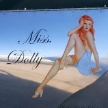
 Jared Isaacman bought his MiG-29UB. Bio P4 points
 -
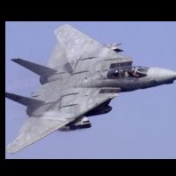
I wrote it here many years ago, but I'm missing the century series, F-101/102/106, F/RF-84F, Mirage F1 AND the FG1, FGR2... and concerning the jets much more4 points
-
The 3 subassemblies dry fitted. To be fair, you can fit all the rest of the parts, if you're confident enough, with PVA glue, and use the rigging to hold em all together.4 points
-
WNW Sopwith Pup RNAS
Bobs Buckles and 3 others reacted to docdodj01 for a topic
Cockpit built up Dry fitted the detailed Instrument panel onto the cockpit And decal instrument faces placed on after4 points -
 My dad flew B 47s. One thing he always drilled into me, never loan anyone your nukes. They never return them. Or maybe it was favorite book?4 points
 -
.thumb.jpg.8c06f26b72413f225c9d0a29e5748f69.jpg)
FM-2 Wildcat 1/32
TAG and 3 others reacted to Vince Blackburn for a topic
A belated Happy Easter to you all. I've been busy over the weekend getting lots completed a pair of drop tanks ready for installation followed by all the little bits 1x propeller 3x masts 1x pitot tube 2x nav. lights 1x canopy rear section This was followed up by starting the exhaust stains with oils which wasn't giving me the effect needed so they were completed with Tamiya smoke and Tamiya Dark Earth Last picture shows the Martlet 3 which is catching up nicely' decal roundels throughout although the fuselage ones where laid over a white disc of paint due to the dark colours underneath the fin flash was masked and sprayed using Tamiya acrylics, "F" was the same but this took an hour and twenty minutes to mask two "F's" and three minutes to spray them white. Regardless very pleased with the outcome.4 points -

Bf110G-4 (early)
Rockie Yarwood and 3 others reacted to mozart for a topic
Took my courage in both hands this afternoon and had a go at doing the mottling, I tried to achieve a kind of spider's web effect and I think I'm reasonably happy with the result, though there's a little corrective work to do in one area where the airbrush decided to spit! Mask-cutting later for the crosses etc.4 points -
I present to you the well-known ACADEMY kit as a Greek f-16 of 340 squadron by 115 Combat Wing. I used after market materials like as: inerior cockpit,seat belts and mask by EDUARDS wheel bays και wheels by the AIRES landing gear by the SCALE AIRCRAFT CONVERSIONS Engine exhaust GT RESIN static dischargers MASTER Decals by THREE STAR DECALS AGM-65 By FLIGHTPATH The colors I used for the camouflage were: for the fs36307 the GUNZE H324, for the fs36251 the AKAN 77100, for the fs35237 the 72043 AKAN3 points
-
decals are started on the fuselage and stabilizer3 points
-

FM-2 Wildcat 1/32
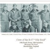
TAG and 2 others reacted to Warbird Kid for a topic
Excellent job on the FM-2! As an addition (and hopefully these will help), I have these images scanned from the album of one Erwin Mott Jr. from Bridgeport, CT. We have a display with some of his flight suits from his long career spanning WWII (when he was flying these Wildcats in the Mid-Atlantic) into post war Naval Air Reserve. Enjoy.3 points -
FM-2 Wildcat 1/32
MikeMaben and 2 others reacted to Vince Blackburn for a topic
A very interesting point was raised by Joachim and after some digging about on the internet I found this Aircraft no 8 most definitely has a white painted hub and cuffs Aircraft no 5 is natural metal hub. if I can find a spare prop the spare can be painted with white hub cuff and then I can have fun at model shows swapping them every now and then.3 points -
Missing this a lot3 points
-

Hasegawa 1/32 P-51D Mustang
Model_Monkey and 2 others reacted to LSP_Kevin for a topic
They come out of the packet looking exactly as you see them. I also used a set on my Trumpeter Birdcage Corsair project, but couldn't quite get them to seat correctly: The Moskit brand is long gone now, unfortunately, though apparently ReXx makes a similar product. Kev3 points -
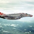
Hello, this is the first Harrier GR.5 to be completed and flown, the ZD318 alias DB1, as took the air for the first time on 30 April 1985 at BAe Dusnfold flown by the company’s Chief Test Pilot Mike Snelling. This was a Development Batch machine that was never handled to the RAF and remains to BAe for his entire life. Now he is preserved as a GR.7A in the Harrier Heritage Centre inside Royal Air Force Wittering. The colours denote the work-share between the main manufactures, Bae in the UK and McDonnell Douglas in USA. The following photos are posted for modelling discussion only. All the rights are by the authors. The model is the 1/32nd Trumpeter GR.7 kit converted/backdated to a GR.5. All the conversion parts are made from scratch by me: MIRLS bulged nose, instrument panel with the Moving Map Display, MB Mk.12 ejection seat, rear ventral chaff&flare dispenser box, wing pylons and ventral pylon. I’ve made the FOD air intakes too. I’ve also correct: all the undercarriage legs, the wings profile, the ventral strakes, all the ECM/RWR lumps and bulges, the four engine nozzles. Aires resin sets were used for the front undercarriage bay and the main cockpit tub, the IP cover and the canopy frame. Some PE parts came from the Eduard set, as for the hot-nozzles shield plates and minor details. All the fuselage, wings, tail planes panel lines were completely rescribed correct. All paints are from the acrylic range of Tamiya for airbrushing and Vallejo for bush use. As I said before, the colours denote the materials used in the construction of all the Harrier II: front fuselage and main wings are made with Carbon Fiber Composite, the rear fuselage section is made with metal alloys, other in aluminium, fiberglass, titanium, acrylic, steel and others. The few decals for the necessary safety/resque markings, the cold-nozzles angle calibration and the serial number/identification number are from various spare decal sheets. CIAO! Piero2 points
-

Fw 190D-9 W.Nr. 600424 Lt. Heinz "Heino" Sachsenberg
BrentE and one other reacted to Miloslav1956 for a topic
1/32 Hasegwa model, Aires cockpit, Cowling & Gun cover from Real Model, Eagle cals, Barracuda wheels, HGW wet transfers & rivet set, Painting mask homemade, All colours MRP2 points -
2 points
-
When I noticed this beauty on Ebay i could not resist myself. From the moment HPH launched this model it was on top of my wishlist. But the MRSP kept me from buying it.2 points
-

1/18 Scale Blue Box F4U-1A Corsair Modification
ctayfor and one other reacted to brahman104 for a topic
Sucks to hear that Jay! I know pretty much everyone reading this would say "don't worry about it, and you're the only one who's going to know," but I know the extreme levels of dedication you've gone to with this build to get everything as it should. Having said that, the realities of war might afford you some leeway. Most of these aircraft probably had an engine change at some point in their lives and an earlier one may well have still been in the supply chain at the time. Same could probably be said for some of the other discrepancies you've found. I know a lot of research goes into the documents you're getting your information from, but there's even still bits and pieces that happened to these frames that weren't especially well documented. Take the B-17 or B-24 for example, there's so many modifications that went on not only during the production runs, but also intermediate depots and then sometimes by individual crews to make up for deficiencies in the field, and perhaps even several times over the course of their service. Realistically (and I know that you know this ), unless you have the actual aircraft in front of you and you are modelling it as it stood that particular day, can you really be certain that what you've depicted couldn't actually be correct at some point? Certainly not trying to downplay your revelations here Jay, but you've got one hell of a model and it represents an extraordinary amount of talent in it, who could stand before you and argue any different? Just my thoughts Craig2 points -
FM-2 Wildcat 1/32
John1 and one other reacted to Vince Blackburn for a topic
Hello chaps Been digging around in the spares box and found a prop Also found a picture of a white hub and cuffs supplied via Joachim That will look nice with the data stencils still on the cuffs2 points -
I have officially lost my mojo. I think it is because my next task must be to add clamps to the engine mount for all the various systems lines and wire bundles. No fun, but I must do it now. Meanwhile - a reminder of my subject (currently): Ignore the "F4U-1D" - that is in error. I picked this subject a couple years ago. I have taken pride in all my previous 1/18 builds to not have any "anachronisms". That is to say, to select a subject (so far mine is Jolly Rogers #29, Bu No 55995, line number 1636, pilot Ira Kepford), and not put on that subject a feature that doesn't belong on that subject. Line number 1636 - remember that for the discussion that follows. We all know, or should know, that wartime aircraft underwent alot of changes throughout their service runs. That is certainly true of the F4U. So how picky should we be.... I know it is possible to go too far and be too picky. After all, most modelers are not privy to the engineering drawings or parts manuals as I am (subscribing to Aircorps Library). But alot of it is important, and visible. So I have recently discovered some dismaying things about my plans for this subject. One of the most important, in my opinion, is the incorporation of pressurized ignition on the engine, and incorporation of water injection. These are visible items, easy to pick out (although for the latter only if the accessories compartment is open). Pressurized ignition - R-2800's with pressurized ignitions have entirely different distributor housings and ignition harnesses as opposed to earlier unpressurized versions. These items are prominent on the nose of the engine. My engine has the earlier (unpressurized) version, like this: Dana Bell volume 2 states that the pressurized ignition became effective on line number 1551. 85 units BEFORE my subject was manufactured. Uh oh. To me, a deal breaker. I must now select a different subject, with a line number at or before 1551. Either that or have an obsolete engine in my subject. No way. Water injection - this was added at line number 1552, 84 units before my subject. And I had no plans what so ever to add the water injection equipment to the engine accessories compartment. Too complicated! So again, I need to change my subject to an earlier one. But, the pressurized ignition problem above has made this a moot point. Also dismaying to me is cowl flaps. All early Corsairs had cowl flaps that extend all 360 degrees around the cowl. This led to problems in service where oil leakage (or other fluid leakage), when cowl flaps were open in flight or take off, could spew out of the gap and deposit itself onto the windshield. This was eventually fixed in production with a "dead flap" fairing which replaced the top three cowl flaps. I provide a picture from the parts manual showing both the "before" and "after" shoulder configurations under the cowl flaps: You can see the fixed fairing which replaces three cowl flaps on top of the aircraft fuselage. And I went through the trouble of Rhino modelling it and having it 3D printed: That pic doesn't include the cowl flaps themselves but hopefully you get the message. But the "dead flap" it didn't come on line until line number 2325, fully 689 line units AFTER my subject! Whaaa? How could I make that mistake? Here's how - I wasn't paying attention. I have seen many pictures of early F4U's - birdcage versions or early -1A's - with the top three cowl flaps shut. I assumed wrongly that the later "dead flap" was installed. No, instead, a field modification was incorporated to bolt a fixed plate over those flaps to keep them closed. I think the mod was fairly simple. It was not incorporated on every unit in the field, but many including my subject #29. So what am I gonna do? I am going to abandon my beautiful 3D printed dead flap part, and Rhino model another curved shoulder for the top of the diaphragm, which accepts the full array of cowl flaps. I am undecided whether or not to have a simple plate over the top three flaps - I make that decision later. I am inclined to.... and I am accepting suggestions. There is more. The bomb window - I thought it was discontinued on the first F4U-1A (line number 0950). Well it wasn't. It stayed with the configuration, according to Dana Bell, until line number 2531. 895 line units after my subject, and almost to the point where the -1D model was introduced. Really??? So I decided to double check Dana and ran into troubles. First, the parts manual provided in Aircorps Library is a 1945 edition, and doesn't even show a bomb window at all! What an omission - it shows all manner of previous configurations back to the bird cage versions, all over the airplane, but not the bombing window? I checked the drawings. Sure enough, the drawing where the bomb window is called out (VS-10250 - "Fuselage Assembly Complete"), in one of its late revisions and not earlier revisions, specifies the replacement aluminum lower panel for the bomb window and it incorporation point. But alas - the note that defines its incorporation point is too fuzzy to read!!! I can however tell when that note was added to the drawing by the revision block descriptions, and it appears that it was added in late 1943, whereas the -1A version of the Corsair was introduced in early 1943. This tell me many -1A's retained the bombing window. But I am unable to verify just which line number the aluminum panel came on line. Of course, if you follow this build, you already know I skinned over the bombing window. And it's going to stay that way. So, I am going to pick a subject before line number 1551 as described above, and that subject probably but not certainly had a bomb window. And I must live with the anachronism. Oh well....I feel stupid. I cannot tell you how many times I chose a configuration to build based on line number 1636 (the Ira Kepford aircraft). This is especially true in the cockpit. And now I am going to abandon this subject and go with an earlier aircraft on or before line number 1551. I don't even recall which configurations I modeled will become invalid. But it's just as well - the #29 Kepford aircraft is so popular that I feel like doing something different anyway. I would still like to do a subject from fighting 17 (Jolly Rogers), and there are many which would fit the bill. I'll decide before too long - I have more to build and I would like to settle on a new line number so I can continue trying to put the right stuff in there. A post on the accessories compartment will come soon. Take care.2 points
-

1/32 - F/A-18C (Academy) - VFA-86 Sidewinders "CAG"
Zola25 and one other reacted to chuck540z3 for a topic
Another beauty! I can see that you made several corrections like reducing the angle of the rear flaps and adding downward leading edge flaps, to make this model extra accurate. Cheers, Chuck2 points -

Wolfpack Phantom - 8th TFW F-4C
Anthony in NZ and one other reacted to alain11 for a topic
hi great job inside this bay !! it's not easy to add some wire into this narrow well , it's very convincing, and enough "busy"2 points -

1:18 21st Century P-51D Conversion to "B" Model With Metal Finish
patricksparks and one other reacted to JayW for a topic
Patrick - I am sooo jealous. Such delicious detail. I find that every time I sidle up to the modeling table these days, before long I have adorned my face with high magnification googles and intense lighting. Subjecting myself to ridicule and ribbing from my wife at times, if she comes in to interrupt me. No doubt, unless your eyes are super-human, you do this too? However, I can only hope to get my detailing as pure and clean as yours (Peter C being the benchmark on which we all aspire to). On my old D-model (Miss Velma) my rudder pedals (made from scratch and nowhere near as nice as yours) are quite invisible under the IP, more so than some other types (the Corsair peddles are more visible). Although I love your peddles (good to know ModelMonkey will work with us 1/18 modelers), they are going to be unseen. BTW - those springs are terrific! Where did you get them, or if you made them, how did you do it? When I make my springs (the Corsair has them too, plus the tank jettison mechanism and the landing gear folding linkage), I have great trouble with the ends, not the coils. A word about radio equipment - ETO Mustangs did not use the Detrola antenna system. Therefore, if you are doing a ETO Mustang, you do not have to worry about the large floor mounted bracket, the large radio box, and importantly the long aerial wire extending to the tail. If you knew already, cool. If not, many can't believe it. But check it out - it is true. Oh, and the nuts around the windshield frame - very nice touch, and convincing. What are you using for tiny nuts and bolts? I use "Meng Nuts" with only satisfactory results (not outstanding). But they are not too costly, and not too time consuming, and more accurate than cutting off hex stock or cutting hex patterns from plastic sheet.2 points -

Trumpeter F-8C Conversion, Brown Bear's 1 V 6 Duel (29 Apr: Done)
easixpedro and one other reacted to jeroen_R90S for a topic
Honestly...? I'm not getting really enthusiastic about the green and I'd stip it (especially if it comes off easiliy) I always though this was a pretty cool scheme I, one day, intend to do on my AZ '17, with blue-tak shapes covering the metal finish. By the way, if you need them, I have some markings (including the nose numbers separately to puzzle your own together) for 1/72 VPAF MiGs, just let me know if you're interested and I'll look the sheet up. Jeroen2 points -

F-35A Italeri 1:32
Aircav1980 and one other reacted to Koralik for a topic
F-35A Italeri 1:32, As always, I made the model straight from the box. However, I did add some shadows and differences in the shade of color so that this one-color painting would be a bit more interesting.2 points -

RA-5C Vigilante - scratchprinted
sandokan and one other reacted to Starfighter for a topic
Printed clear parts need a lot of attention, at least the ones I did so far. Here's a little comparison between the part coming from the printer (with supports removed) and an identical part after several weeks of sanding and polishing.2 points -
Next will be the propeller, engine, fuselage, wings and tail feathers...I guess Special Hobby is planning a new tool Willow..2 points
-
SH / ICM AH-1G early cobra in 1/32(we got personality now)
Javlin1 and one other reacted to oppenheimer for a topic
So far a have finished the front and middle section of the cobra, and i am happy with the results of the weathered paint2 points