Leaderboard

Popular Content
Showing content with the highest reputation on 01/18/2019 in all areas
-
"Glamor shot".8 points
-
I was going to wait to post this build thread until I got farther along, but thought that it might be a good complement to Garage21’s Sopwith Camel thread and kkarlsen’s amazing Fokker Triplane thread. By the way Kent, your build thread is what inspired me to start this build, so thank you. After working on my 1/16 scale Stearman and realizing that I had bitten off more than I could chew with my first model in decades, I lost interest and eventually stopped work on it a while back and decided to look for something that would excite me more and start again... maybe in a smaller scale with something a little simpler in order to move quicker. Then I saw Kent's Fokker Dr.I thread as mentioned and decided to jump back in. I decided on a 1:24th scale, built from scratch Fokker E.III from 1915: Jerry Boucher, the artist of the above Fokker E.I painting (© J.J.Boucher) kindly gave his permission for me to use it in my post. Please visit his website, his work speaks for itself in its quality and presentation: www.the-vaw.com This was a very simple aircraft and there are some excellent resources online... though I am going to have to recreate the scale drawings necessary to build this plane as there are no complete plans easily accessible online (that I have found). As you will see I will be building the aircraft in the computer in order to generate good usable scale drawings and then will use those as the basis for my build, which will mostly be plastic and resin, with brass and/or aluminum parts used as necessary. I will also be building many of the difficult parts and assemblies in the computer and using my 3D printer to supply them. This entails a lot of trial and error as you will see. For those interested I have an Anycubic Photon 3D printer which is an LCD (Digital Light Processing) DLP printer... basically the 3D model file is sliced into masks of varying size (set when setting up the 3D model), the light from the LCD shines through the unmasked portions of the 3D file hardening the printed part one layer at a time as the build plate rises from the resin tank. At the finest setting it can be set to an accuracy of .1mm, which provides amazing detail. Here is my 3D fuselage (frame only) model... I will discuss the fuselage assembly first:7 points
-
"The Star of Africa" - Hans-Joachim Marseille's Do-335 A-2/Trop - Yellow 14 - FINISHED!
Paul in Napier and 6 others reacted to Out2gtcha for a topic
First up, I finished the elbow rest for the Ruhrstahl X-4 control stick. Since no pics of the actual elbow rest exist (that I know of) and the fact that this is a later iteration of the X-4 this is what mine looks like. Its not perfect but looks the part IMHO. It actually swivels and locks out of the way, swinging back toward the console, but I have it locked in the extended position so people can see what its actually for: Next up it was time to make sure the fuselage was closed up. I got the fuselage closed up, and the spine graphed on. The fit on both was actually pretty good: Next up, I got the QB exhausts painted and installed. These were not rusted out, nor super weathered ,but I used Alclad jet exhaust, followed by some Alclad pale burnt metal, and then some flat clear with soot on the tips. All sounds complex, but the colors sort of blended more than I expected They actually look much better IRL than in pics: Then I took some time and got the engine covers installed. This took some doing, as the rear engine covers were a tight fit, and getting the trailing edge around the exhausts was a bit of a task. For this, I was in a quandary about how to mask all those exhausts stacks off. What I ended up doing, was some fancy dancy masking, by actually making a pocket of tape for the exhausts and attaching them to the panels before gluing in the engine cover panels, both front and rear. This seems a bit odd, but it resulted in a very tight mask around each exhaust set on each side. So far this has worked out better than I hoped, but the litmus test will be once the model is painted, as I will see if the tape comes off as easy as I hope it will. I made sure to attach the inner portion of the tape with minimal attachments to the inside surface of the engine covers, so when it does come time to remove the tape, there wont be a lot of tape holding things in place from the inside. I also could not resist putting the cowl, cowl flaps, rad front and both props on as a mock-up to see what things are going to look like: As you can see, I also cut down the port side exhaust intake shield, as I thought it looked odd extending so far beyond the rear of the exhausts: Both rear engine panels did fit, but they were tight, and will need a bit of finish sanding/tidying up: All in all, Im very please at how fast this one is going together, and how well its turning out: Tomorrow today (starting right now actually!) we are supposed to get 6 - 10" of the white stuff, and hit a low of -5F, so the boss just said to work from home. That means its Friday and Ill be working on work model stuff here. I think tomorrow I will be hitting the spares drawer to see what I can find in the way of louvers or scoops for some extra rear engine cooling for the A-2 Trop. I also got the Eduard exterior in, so am also going to try to get the rad screen painted and installed as well. As always cheers and thanks for dropping in on me!7 points -
Hello everyone. This is my maiden post here on the forum although I’ve been lurking around for about a year now. I really enjoy following the amazing builds on the site, what a talented bunch here. I’m 43 years old and have been an aviation buff since early childhood. I am new to modelling, as I never had the opportunity when I was a child. One of my favorite toys growing up was an already built Corsair model that I found. It was only the fuselage and wings, the rest had fallen or broken off before I found it. Regardless, I loved it haha. Now some 35 years later I’m building my own Corsair. I’ve built four 1:48 scale fighters over the past year and I’m now stepping up to 1:32. I’m still very green at this and the only thing I have going for me is I have a cutting mat and I use Tamiya thin cement (so I at least look the part!) I will do my best with this build and I would surely appreciate any feedback. Please don’t be afraid to give it to me, you won’t hurt my feelings. After all, I would like to improve and advice from others will help me tremendously. I may not always make the suggested corrections with this build but I will certainly take the advice for future projects. Hopefully others new at the hobby that are following this thread can pick up some tips from my mistakes. On to the build. I’m building Tamiya’s 1:32 F4U-1a, everything straight from the box and I’m not adding any scratch built parts. Just keeping my fingers from being glued together will be a challenge enough for me. I’ve read great things about this kit so I thought it would be a nice introduction for me to larger scale planes. I haven’t decided whether or not to do the engine as I like the look of a closed up bird. So far I have the cockpit pretty much buttoned up. Here’s my progress so far.. Thanks for looking and allowing me to share this build here. -Robert6 points
-
Fuselage Frame After a lot of research online I discovered that the drawings easily found online were not as accurate as I would like, so I decided to build it in 3D in my computer... then used that as the template for the physical model. This is the template drawing I generated from the 3D model. The color coding breaks down as follows: Light Blue - 3/64" plastic rod (main fuselage structure) Dark Blue - 1/16" plastic rod (Landing gear support) Green - 1/32" plastic rod (cowling internal support) Purple - 3/32" plastic tube (Tail surfaces support) For simplicity I decided to build this out of plastic...I originally had planned on using brass or aluminum, but decided that Plastic gives me a lot more flexibility and control, and is easier to work with. I bought a simple magnetic whiteboard (small) and some magnets... one type comes in a roll that I could cut and use as guides (see the image below), the other type are very strong map-magnets that I used to hold down clamps as shown. Once both side structures were completed my problem was how to keep it all square when adding the connecting structure... what I came up and why I am using a magnetic building board, was using the magnets and several 2" angles.. I used the clamps to pin the structure flat.. this insured the structure was square in width and height. Note that I am using the part of the plan marked TOP, this is because I am adding the structural supports for the top of the fuselage (it is top down in these images) As I moved down the fuselage, I had to slide the angles down and move the clamps at each frame station due to the curvature of the rear half of the fuselage. ... I then rotated the entire thing 180 degrees so I could do the same for the bottom structural supports. Note that I have moved the frame to the part of the plan marked BOTTOM. The completed fuselage frame:6 points
-
hello fellows Slow progress since the last update, but thought i'd post couple picture before I start the internal rigging Very enjoyable when i get time on the bench6 points
-
Well, it happened faster than I expected. I was watching the Anycubic Photon in my Amazon wish list, at 430 USD, and it suddenly went on a "lightning deal" for 373 bucks, so I pulled the trigger. Considering I had 40 bucks credit with Amazon from Christmas, I wound up about 360 after tax. Guess I better get that 3D software learned now!!6 points
-
Me-262 1/32 details
hayaman and 5 others reacted to johnie hopper for a topic
As I promised I'm sharing few pics of future set 01 (maybe there could be another set with cannons, FuGs, mother compass etc.). I created SW10 panel as alternative to ZSK. Maybe it's not accurate, but it is very similar. Also KG13 is repaired. I made another version of main flight instrument panel, but according my details there is horizontal offset 11 mm between repeater compass and horizon. Pilot seat is not completely finished yet, but for imagination it should be enough. There is place for REVI EZ 42 (if I will find some useful drawing). You can find pressure vessel for vario and convertor (both ahead of instrument panel). Any other idea? :-)6 points -

ICM 2019 Catalogue
Rick Griewski and 4 others reacted to LSP_Kevin for a topic
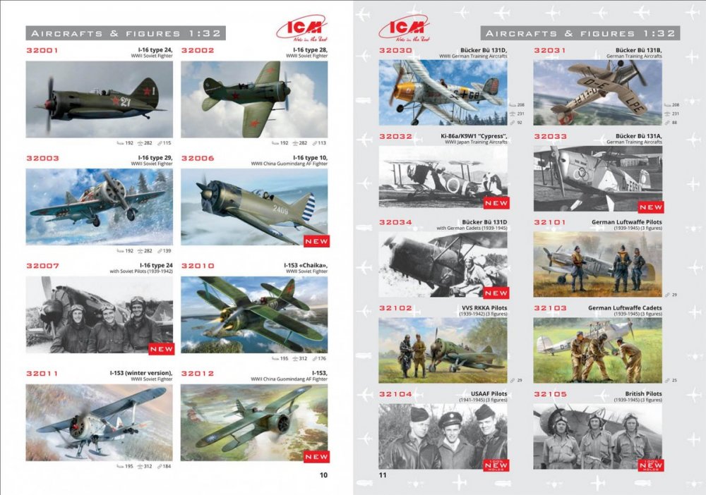
ICM has just published its 2019 catalogue: https://issuu.com/7727025/docs/catalogue_web_2019 It's quite expansive - I don't think I quite realised just how prolific ICM has been in recent years! Here's a peek at the LSP pages: Good to see them expanding their range of figure sets! Kev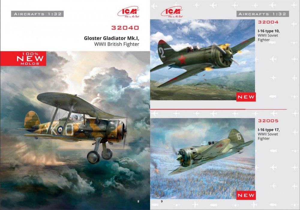
 5 points
 -

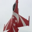
Lockheed Martin F-16CJ Blk 50 1/32
Model_Monkey and 4 others reacted to alex1688 for a topic
It's Tamiya kit I've built on Nov 2018.5 points -
Found this posted on Silver Wings FB page . It's a D.XXI w/Wasp engine. Simon said they weren't gonna do this one. Wonder what's up. Hope they changed their mind5 points
-
small progress fit was so far great after I have attached the nose I have realized that I dont like the shape of the lower part of fuselage behind the nose, will check some reference pics fuselage taking the shape 30mm cannon, it will be almost completly hidden wheels wells thanks for looking jan5 points
-
Nearing completion of the cockpit: Some more wood work... More soon...5 points
-

1/32 Gotha G.I Scratch Build
blackbetty and 4 others reacted to guitarlute101 for a topic
Just a quick update, The fuselage is primed and everything is smoothed out nicely and I've drilled preliminary holes for the wing attachment points...………….. I'll have to add the reinforcing strips later after I've completed the rest of the upper fuselage. Thanks for looking in, Mark5 points -

1/32 Hasegawa P-40E Finished
Anthony in NZ and 4 others reacted to fightnjoe for a topic
Ok friends a post with two objectives. First: I have begun the weathering on the 1/32 Hasegawa P-40E. Using both a cheap set of oils and Abteilung 502 paints. I want to give this build a finish that suggests a story of an aircraft that has seen some hard use but is still airworthy. The aircraft was based out of India and supported flights over the Burma hump. Now the second objective is the quality of the pictures. I have spent quite a bit of time over the last four or five days trying to dial in a better quality picture. These are the latest in the test. Please all comments, critiques, and criticism are encouraged. Joe5 points -
4 points
-

Trumpeter Swordfish 1:32
Model_Monkey and 3 others reacted to Fvdm for a topic
Before I could prime the fuselage i had to place some more parts. One of this parts was the lower center wing. And man o man, did I mess this up When I glued this part I saw something strange. I looked at the model, I looked at the manual , I went to the wall en hit my head against it. In the manual you will see at the end of the toothpick some sort of adjusting. Now look at my piece eal Something did not go wel here. While cleaning this piece i must have tought this were some kind of sprue or something so i cut it off.......... A well, after realising what I had done I had a good laugh en fixed it with some styreen rod and a piece of a earbud. This will do for me. After this I sprayed the fuselage in the primer and went on with the wings. I had the idea of cutting out the ailerons but there seems to be a different between the top side and the bottom side. The piece of tape is of the same lenght. When the aileron moves upwards, the pivotting points are at the black stripes. (Is it called pivotting points or is it called hingeline?) But where are the pivotting points when the aileron moves downwards?????????? I really have no idea and I can't find it in the references so I think I will leave it as it is Thanks for watching.4 points -
I also added more wires and whatnot to floor, as well as port fuselage wall (still not quite finished yet, but almost).4 points
-
Tonight was very productive. I fine tuned the cannon cover top.4 points
-
CAD exercise nearing completion with the large centerline ML type G winch and pylon "good enough." I have yet to draw up the generator blades for the front of the thing which I hope to do over the weekend. I'll also draw up the cable guides for the tail and a few additional parts to make this conversion look right in the coming days.4 points
-
OK - I think I've figured out how these 100+ turnbuckles and turnbuckle/clevis components are going to be fabricated. Solder is definitely superior to super glue and the copper safety wire looks great against the brass buckle. I was also concerned that the final piece wasn't cleaning up as well as I liked but as I look at these photos, I kinda like the "grimy" look. I just realized however that I forgot to add the hex nuts at each end to allow the turnbuckle to be tightened. Hopefully the third time will be a charm. I think the safety wire in this picture may be a few millimeters too thick, but it's all I had in the shop tonight. I'll go with a slightly skinnier garage and I think we'll be right there. I almost cheated today when I was at the hobby store and discovered a set of Proctor Turnbuckles. But in the end, I think this looks better. Now I just have to figure out how to fabricate 100 of these given the fact that this ONE took about an hour!4 points
-
Thanks Squizzy and Ben, appreciate your interest! As soon as the windshield is in place and the cockpit masked off, the model seems to accelerate. You can actually read the history of my fitting ****-up by the layers of styrene, much like the rings of a tree trunk! It does sit nice and snug now, and an added bonus was that I had to squeeze the sides a bit to make it fit, which in turn pushed the profile up a bit from what was a slightly flat frame. Some added depth to the rivets and panel lines at the fin "join" as well as some different fasteners to add interest to the surface. The static-wicks are from Profimodeller, but look a bit too long to me. The control surfaces have three skin layers, which I recall Karl replicating with actual layers! I just accentuated the first panel line to create an impression of depth - cheating... The APU intake is mounted on some thin styrene card, and these lifting handles created from the same 0.13mm sheet. The chaff and flare dispensers need a bit of extra attention, and the side fairings really help the look. Stretched sprue for the weld seams and carefully fill and sand the cover to get it flat. The kit photo-etch intake grilles really look the part. Now at last some of the pedigree created in the Design Bureau is starting to show. What a shape... Still no soldering , back in a week... Sean4 points
-
Hi guys! This is the kit I like to participate with. I'll start building it asap. Håkan3 points
-
F-86F Hasegawa 1/32
Model_Monkey and 2 others reacted to alex1688 for a topic
I've used the Hasegawa 1/32 Canadair Sabre Mk.6 kit to build this F-86F on the beginning of Dec 2018. I was interested in exploring the visual expression of Natural Metal Finishing type of aircraft. I've used the Alcled II lacquers for the painting. With the limited colors and experience I have, this is best I can do at that time. F-86F Sabre 40, Hasegawa 1972 kits, rebox on 2005, 1/32 with raised panel lines.3 points -
Thank you for the kind words. I made some more progress: installed the cockpit and radio operator compartment. It’s a very deceptive kit: it looks like it is going to be an easy fit but actually the main components do not fit at all without careful sanding. I was forwarned by Wouter’s build but it not expect it to be so difficult. Since these pictures I have managed to close the fuselage. I need now to clean up the seam and rescribed the lost details. More pics this week-end. Cheers, David3 points
-
1:18 Hobbyboss AV-8B Harrier
Greg W and 2 others reacted to patricksparks for a topic
Spent a couple hours putting in some more screw heads..I must have some loose ones in my head.. I used slightly larger screw heads than what I guessed as to what they are on the real thing, I figured the heads are probably in the 5/8"-3/4" diameter range, the heads I used are about 1" in scale at first I thought they might look too big but when paint goes over them they look alot smaller than what the raw brass looks like.3 points -
cool project Bill!3 points
-
Thanks guys! Chuck sent me a PM wondering about my Aim-9X, since I chose to model the training round with fuse windows and open exhaust. I actually researched both of these points, as far as the exhaust is concerned there are plenty of pics out there showing training rounds with non-blunt rear ends, see e.g. here. I could have sworn I found pics of raining rounds with fuse windows, I specifically remember a pic of a Superhornet with a trainer that had fuse windows. But since I wasn't able to find suitable evidence anymore and I am wondering if my memory is failing me, I doubled back and created a cover for that section of the missile, which together with the seeker cover seems to be standard when they are on the ground. Fortunately, Zacto provides a neat nose cover. I am pretty satisfied with the result, it adds a bunch of color to the overall model, it's already hanging from the wing. Cheers, Marcel3 points
-
I love your definition of "something a little simpler". 1/24 scratch built Fokker. My definition is 1/72 Airfix.3 points
-
3 points
-
lol - Wasnt trying to imply anything! I had to do that with my gift too, and I JUST barely made it under the 36" mark where the USPS price jumps up. Just making sure everyone is communicating (both directions) Sometimes we have had instances of confusion on the raffle, where something happened (nothing intentional at all) and parties got a bit upset, but it was only due to miscommunication. Thanks Mike!3 points
-
Thanks for looking in....but shock horror, i have found a short shot in a WnW kit But its ok its the hidden petrol tank so I'll probably do a bodge job pack and move on. To be honest the 3 petrol tanks are not what I have come to expect from WnW, the seams are way out and the parts concave, i have seen other builds where people have used plastic card discs to cover the whole diameter, but i dont have a punch so i'll fill and sand3 points
-
The 2nd 1/32 kit in my Natual Metal Finishing projects. I spent most of my 2018 Christmas and New Year holidays on it. F-100D Super Sabre 1/32 Trumpeter Kit with Alcled II Lacquers. I've tried not to ink on any panel lines. Instead, using the delicate control of airbrush and compressor PSI to express the idea of metal panels.2 points
-
ICM 1/32 MiG-25 Foxbat?!?
Daniel Leduc and one other reacted to thierry laurent for a topic
Does this guy know something most of us do not...? https://www.shapeways.com/product/NSQ7TUYSJ/1-32-mig-25-foxbat-exhausts-short-type?optionId=71199182 I'm afraid this is too good to be true but who knows...?2 points -
1:18 Hobbyboss AV-8B Harrier
Greg W and one other reacted to patricksparks for a topic
A little more photo recon revealed an access panel that shouldn't be.. so have to fill, too bad I didn't notice until after I opened all the fastener holes for photo-etched parts, well at least I didn't glue all those in .... this panel is only on the left side of the cockpit.2 points -
2 points
-
1:18 Hobbyboss AV-8B Harrier
patricksparks and one other reacted to Fvdm for a topic
Wow, those fasteners are awesome. Stil a few more to go?2 points -

F-16A & F-16C Aggressor Double Build - The Double is Done!
A-10LOADER and one other reacted to chuck540z3 for a topic
Great "Save" Marcel! I bet 99% of the modelers out there would never have noticed the fuse windows, but what you've done with the covers is way more realistic for a missile on a parked jet anyway. Cheers, Chuck2 points -
1:18 Hobbyboss AV-8B Harrier
Anthony in NZ and one other reacted to patricksparks for a topic
AWESOME !!!!2 points -
Good idea. A bit more drivel from me about this. As I said earlier if you are going to bite the bullet and do it freehand (I think tis the only way really) then get things together to be able to brace your arm on something. Have some sheets of paper pretty near the model to practise on. Get the old muscle memory going and keep going on the paper until things are consistent then just move quickly across to the model (or move the model to your existing position) and carry on. If you bork one up don't stop but do another and come back and fix it later. Just my warped opinion of course.2 points
-
The famous order issued in September 1944, which introduced 81/82, stated that 71 was to be discontinued and 70 would continue to be used for props. My point is this: there seems to be a generally-accepted attitude that after September 1944, there was NOTHING other than 81/82/83, even in the cases when we clearly know that 70/71 was used. For example, how many models of Do 335 or Ar 234 are painted 70/71? Everyone paints them 81/83, without exception. Radu2 points
-

2018 LSP Christmas Raffle Winners
LSP_K2 and one other reacted to Phartycr0c for a topic
Received Shawn's DH 2 in fine order. Many thanks. I know my Hunter has landed with Mick and the Mig book with Maru, just awaiting an update on the B1 book. Thanks again for organising this great event.2 points -

Late War RLM usage of 81/82, etc.
Padraic Conway and one other reacted to MikeMaben for a topic
They were standard on bombers and props thru the end of the war weren't they ? There was likely plenty of it available. Hi Padraic, they're not on your keyboard. They're in your character map or this easier method : alt 132 ä alt 142 Ä alt 148 ö alt 153 Ö alt 129 ü alt 154 Ü alt 225 ß alt 0235 ë alt 0203 Ë may have to type 0 in front of the number. alt 0128 = € I copied the above to a text file and keep it on my desktop. hth Edit : oops forgot the E2 points -
Messerschmitt Bf-109E-3, 1:32, Cyber Hobby
ShelbyGT500 and one other reacted to Hartmann52 for a topic
PeilG IV system antenna2 points -
found some motivation for the second saet and some placement off the parts next up the other ip and mid consol Mark2 points
-
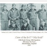
Been working on the bombardier's compartment 110_4474 by Rick Martens, on Flickr 110_4477 by Rick Martens, on Flickr 110_4478 by Rick Martens, on Flickr 110_4479 by Rick Martens, on Flickr 110_4490 by Rick Martens, on Flickr I have added the bomb release switch, bombdoor controlls, a portable oxygen bottle and the springs and pulleys for the two machineguns in the nose. Maybe not all that accurate but it looks fine to me. 110_4482 by Rick Martens, on Flickr 110_4484 by Rick Martens, on Flickr 110_4485 by Rick Martens, on Flickr Could't resist a dry fit. That place is crowded they had hardly room to breathe in there!! 110_4495 by Rick Martens, on Flickr 110_4494 by Rick Martens, on Flickr Also finished the Norden bombsight. Only could't get the crosshairs done. Tried stretches sprue, thin wire ( too thick ) and even the dogs hair so I will probably leave it as it is. Thanks to Daniel I know the noseart Liquid8er 1 by Rick Martens, on Flickr Liquid8er 2 by Rick Martens, on Flickr Rick2 points
-

3D Printing
Harold and one other reacted to SCRATCH BUILDER for a topic
Turbo cad should be ok as long as you give your part thickness, Here's a pic from Blender of my servo's, there in 1/16 scale Printed... And i print all the bolts and rivets i want, i could do about 600-700 at a time, and these took about 45 mins I'll get a better camera soon, But one thing to think about, resin is stinky so have good ventilation, i made a box for mine and vent it out the ceiling to the outside in my work space2 points -

HKM Lancaster
alanash1963 and one other reacted to Smeds for a topic
Nose and tail turrets under construction.2 points -
1:18 Hobbyboss AV-8B Harrier
Greg W and one other reacted to patricksparks for a topic
Finally figured out the mystery instrument panel shroud, countless hours of photo interpertation....no kits have anything close to this thing... the new one is in the foreground the kit part that I tried to modify is at the rear. I still have to put the defogger tubes on the sides of it. \2 points -
Thank you for the offer. I have the WWP publication with a very complete walk around of the Cosford museum Me 410, highly necessary reference given the fact that HPH instructions are rather vague. I plan to scratch build the BK5 and leave the bay open. My understanding is that with the BK5 mod, the Me 410 was not retaining the usual opening mechanism of the bomb bay but the two doors were screwed or riveted together and the whole thing was coming out as a unit when it was time to load or service the gun as shown in the picture above. I will cut the two doors, glue them together and I will look into embedding some tiny magnets in the door so I can show the bomb bay or close it at will. I made some good progress but this kit is not a run in the park, every little piece needs to be cleaned up and you need to be careful doing that as some parts are actually pretty fragile. A set of micro and pico saw from Radu are an absolute necessity. I have started sanding the fuselage. As was noted by Wouter in his build, you need to remove about a millimeter on each side of the fuselage (and more at the tail) otherwise the tail and the cockpit glass will not fit. I am in the middle of doing that but it takes time and it cannot be a rush job, plus it's bloody cold outside so the resin sanding sessions are always short... I am 90% done with the pilot cockpit and 60% done with the radio operator / gunner. I have chosen not to use the HPH/eduard colored etch for the cockpit as it is in a strange shade of blue which does not match the RLM66. I have used the resin pieces as they have pretty good details and used airscale dials and placards plus some careful painting with acrylics. I have cut a few items from the eduard photoetch when I could use them. All in all I am pretty happy with how it looks. On the pics below everything has been gloss coated in anticipation of some light weathering. I still need to add all the levers but will do that when I am ready to install the cockpit in the fuselage to avoid breaking them. As was the case for Wouter's build, you only have one half of the control stick in the box, the top half is missing. I followed Wouter's path by carving the top half from a piece of sprue and added bits and bobs, I still need to add some wires but you get the idea, should look better under paint: That's all for now. It is amazing to see all these ambitious builds going on at the same time, highly motivational. Cheers, David2 points