Leaderboard


Popular Content
Showing content with the highest reputation on 07/16/2019 in all areas
-

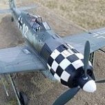
Bf 109 G-10 Erla/type 110, Hasegawa 1/32
109 and 5 others reacted to French frog models for a topic
Here it is finally finished ... the paintings ak real are great to use ... a little rest and zou it will be necessary that I finish the other 109! A huge thank you to Vincent Kermorgan and jean-claude Mermet for their invaluable help! See more on my FB's page: https://www.facebook.com/125768474675320/posts/431152264136938/6 points -
Once again I find myself struggling for quality time at the workbench, but I've managed to squeeze a few short sessions in here and there, so here's the latest progress update. Firstly, I managed to fix the too-wide fuselage at the forward end, by slicing away some of the upper section of the forward bulkhead with a #11 blade, until I could press the fuselage sides into a better position to much the upper cowling part. This at least eliminates one fit issue. Rather than plough on and try to get the nose to fit at this stage, I decided to switch to dealing with the lower fuselage section that goes between the wings. This needs modifying to accept a resin forward part. I decided to use the chain-drilling method for removing the unwanted plastic area (which is what I should have done when modifying to fuselage, too): Note that the resin part is positioned backwards in the photo above. Here's the assembly after the removal, and much test-fitting and refining of the mating surfaces: The conversion instructions aren't completely clear about how to handle the subsequent assembly of this area, so I decided to take what seemed the most logical approach to me. Since everything becomes a bit of a jigsaw puzzle at this stage, there's plenty of room to get things wrong, so I elected to glue the kit's plastic spar to the two remaining locating holes, which I figured would help anchor the resin section in place while the CA cures. However, the join between the resin and plastic parts has a lot of vertical flex, and I could see it becoming too concave or too convex if I wasn't careful, and getting the spar sitting at the wrong plane in relation to the two parts would have made things worse. I decided to tape everything up and fit it to the fuselage, and the poke the Tamiya Extra Thin brush into the wing roots to run some cement into the plastic locating holes and pins. This meant that the spar would set up in the correction position, and I could then CA the resin part into place, confident that the geometry of the assembly as a whole was as good as I could get it. I know that's a pretty confusing explanation of the process, but here's the result: The next step was to fit the new resin locating socket parts for the landing gear, which you can see in the photo above. But these introduced some new fit problems, as you can see below: The solution here was pretty straightforward - reduce the width of front tab on the upper wing root: Much better! But now you can see that the roof of the landing gear sockets is forcing the leading edges apart, so I'll have to reduce those before everything sits how it's meant to. I'll be back after some filing and sanding! Kev6 points
-
After 7 months of work, the Albatros D.Va (OAW) is finally complete...The build is based on the Wingnut Wings kit and finished as Hans Von Gössel's flying skull, circa mid 1918. The kit was extensively modified in order to make the small details more accurate. Additions were Bo Monroe's 3D printed wing radiator and Fuel tank, HGW Models textile harnesses and Yahu photoetch instruments. I completely scratchbuilt the air valve assembly behind the starboard instrument panel and linked the piping based on the NASM plans for the restored Albatros (the restoration book was of tremendous help with the plans and detail photos). The kit received a new windcreen made from thermoformed clear acetate to thin it to scale, and the coaming was modified to add wrinkles and retaining washers for the leather. Master brass jackets were used for the Spandaus. For the engine, i had run out of Taurus resin overhead cam so i just scratchbuilt the valve springs, the induction manifold was wrapped with teflon tape and the heat shields were made from lead sheet and MENG styrene bolts. Taurus resin spark plugs were used and everything wired using Modelkasten rubber thread. Rexx metal exhaust attached. The Niendorf propeller was my first hand carved propeller and i used different veneer sheets and then coated it with MR. Paint clear. The wooden fuselage is finished with Knotless decals from Uschi van der Rosten and a few filters. The decals are just flawless in their application and in the result you get. I initially had the rigging attachment points 3D designed and printed by my friend and ALM Studios team mate Imad Bouantoun, but they turned out too big due to their hollow nature and limitations on SLA printing so i ended up scratchbuilding those using styrene and thermoforming the domes with styrene sheet to be able to use the Gaspatch Models albatros specific turnbuckles. Rigging tubing is from Bob's Buckles and rigging is done with EZ-Line thin. The lozenge linen is Aviattic and is superb as are all the linen decal series from that manufacturer... Alot of additions and scratchbuilt items which would be too long for me to itemize here, or which i might have forgotten over the period of time since. The figure is to give a sense of scale and was painted by my friend and ALM Studios team mate Bernard Bassous. You can find all the juicy details in the build log . Id like to thank everyone who encouraged me to push the envelope so to speak. As i mentioned on the wip log, it looks like the stars were aligned for this one! Thanks again, Stay safe and happy modeling! Karim5 points
-

RAAF FAC OV-10A Finished!
Starfighter and 4 others reacted to ericg for a topic
Thanks Brian. I do like your white EZline idea it looks great. I was a little concerned at how it might react to paint and washes over time though. Another action shot of Graham. Some more work. I tidied up up the wiring, glueing short lengths of plastic rod onto the fuse boxes to simulate plugs and sticking the lead wire into them. They should look pretty good once painted. I carved some T shaped fire handles from plastic card and installed them on the rear IP Much has been said about the way the wings, booms and fuselage join together. This is one area of the kit that I think could have been done a bit better. I assembled a long spar that went from one wingtip to the other. This was made from plastic tube for ease of glueing it into the wings with styrene glue. I then used a length of brass square tube, to allow me to bend and set the angles of the wing in case of any alignment issues and then used some think music wire in the middle for overall strength. Wings attached.5 points -
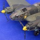
Ju-87B, 1:32, Trumpeter
dodgem37 and 3 others reacted to Hartmann52 for a topic
Ju-87B (Trump) + BigEd + ...4 points -
Hi All, i remember when Airfix first announced a new 1/24 kit was on the way and all of the speculation started.. maybe a p51b, a gloster gladiator, A Corsair (how awesome would that be!). Or even a P38!! So when the hellcat was announced I was a bit disappointed and a little underwhelmed! That didn’t last long and as more and more details of the kit emerged I came around to the idea and nearing release I couldn’t wait to get my hands on it! I’m not disappointed, what a great kit, the plastic is great to work with, the detail is brilliant. And the finished model will have real presence in any collection. I’ve made a start on the cockpit and engine. The plan is to have all the panels open like my bubble top typhoon. And if I’m brave I may also fold both wings but may end up with one out. cheers Matt4 points
-
Wait till you see THIS The pink JS-2 is the gate guard. And the yellow and green "Armoredslidedevice 2000" above is part of the museums playground for children Otherwise all of the display items are properly painted in camo colors or factory finish. Regards - dutik4 points
-
It's been slower progress on the build for the past week or so after I finished the cockpit, although we're moving along. For the past couple of days, I've been laboring in the world of "why am I doing all of this nobody's ever going to see it!" with the Eduard PE set. I must say, though, having completed it (without losing a single tiny part - a first for me!) it is satisfying. The enjoyment of modelling for me is the process at least as much as the finished product. PE addons to the main landing gear and radiator fairings (chiseling off the "L" on the left part was more for practice with a new tool - discussed more below) I had a glue misadventure, unfortunately, while attaching the gun cover panels, and had to do a little rescribing, re-riveting, and sanding. I sprayed a coat of black primer to see how my work looked. I decided to wipe it back off so I would have an even surface for final paint, so I sprayed it down with IPA and wiped it off. This inadvertently gave me a panel line wash/preshading effect, which also gave me a really good look at where my scribing was and wasn't adequate. Starboard wing got the worst of the glue trauma, and unfortunately lost a few of those beautifully fine raised fasteners, as you can clearly see here. In other exciting news, though, my backordered Yahu panel finally arrived, so I was able to do this: Followed by this: Unfortunately, I did something wrong with that landing/ID light that is sandwiched between the fuselage halves, and ended up with about 1mm x 5mm gap along the bottom of the fuselage, which I filled with thick CA glue. I take issue with that light, actually, as well as the one that they ask you to delete in the instructions. Both are, I think, contrary to Tamiya's usual elegant process. The one involves trying to cut out a perfect half circle from the bottom of the fuselage half, and the other involves removing a prominently molded piece of detail from the middle of the wing section, which includes both raised and engraved detail. I'm leaning towards being inaccurate and leaving that as is, because I think the likelihood of my messing up the beautiful detail in surrounding areas is great. I also wanted to take a minute to praise a couple of new tools that I'm using during this build. The first is this micro chisel I got from UMM: http://umm-usa.com/onlinestore/product_info.php?cPath=21_28&products_id=7431. It's a very precise and beautifully (even dangerously) sharp tool, and I've found several good uses for it already. Highly recommended. I also am trying Gator's Grip for the first time. It is a nice thick PVA glue that dries quite fast and strong. I've used it as well as CA for my PE in this project, depending on the particulars, and found it very useful. FInally, these little guys retail for 8.99 at Harbor Freight, and I got them on sale for 5. The 1/8 shank means that they can be used in my Dremel, but it also happens to be a perfect size for using them as hand drills as well. These have already been very handy, and I'm sure will continue to be.4 points
-

Zvezda Star Destroyer - a new detailing project
Greif8 and 3 others reacted to The Madhatter for a topic
So, here I am with another update. The roof is finished - or finished enough for now. It's looking pretty good to me. It's hard trying to keep it all in scale but I think I am doing alright. A test fit of the bridge and neck was okay but I had to remove some stuff off the back left sidewall to allow the neck to slide all the way in. The fit is not the best - I'll be honest, I'm not sure if it's all me, or part me and part kit or just the kit itself. Either way, I'll have to think carefully about how the final construction is going to go. Well, that's me done for another couple of weeks I think. I'll be making a start on the lower level sidewalls tonight hopefully, then the main body which will be very time consuming I think. Till then Adios amigos Si4 points -
I've seen modelers using black primer, but I didn't know the real thing has black primer: Here's the link to the article: https://strategypage.com/military_photos/military_photos_20190713153130.aspx3 points
-

Large Scale Flak - 40mm Bofors Gun
mustang1989 and 2 others reacted to BradG for a topic
A little something I threw together watching the Cricket World Cup the last two weeks. This is Bronco's 1/35 40mm Bofors gun. It's a good kit, well detailed and fitting but with some frustrating points. Some sections are over complicated with detail included that cannot be seen once completed or photo etch that could have been included as molded on detail with a loss of detail. Also make sure you read ahead in the instructions as parts often need to fit into others in steps down the road, if you mess up the alignment you will have trouble down the road. It would also be nice if Bronco included some extra smaller parts as they are easy to lose. It's finished with Gunze Olive drab and weathered with MiG pigments dry mud and European dust.3 points -

RP-3 rockets for Mosquito in 1/32, and placement
Uncarina and 2 others reacted to Darren Howie for a topic
Given we have a beautiful Mossie in 32nd and Strike wing Mossies are a popular subject would you think a dedicated Mossie rocket set would be a good seller? Id be up for at least two sets...3 points -
Looking for someone that can cast resin
Pascal and 2 others reacted to thierry laurent for a topic
I am crossing my fingers for you. In any case you should cut the rear wing as this kind of undercut is very difficult to cast. Resin casters typically separate the shapes to get correct casting results and avoid damaging the molds.3 points -

Hanriot HD.2 scratchbuild
Rick Griewski and one other reacted to kensar for a topic
This is my scratchbuilt Hanriot HD.2 I built for a group build on WW1aircraftmodels.com. The only commercially made parts are the engine (WNW), machine guns (Eduard), and instrument face decals (Airscale). Enjoy!2 points -

HK Lancaster , The Dambuster version
Azgaron and one other reacted to Phartycr0c for a topic
Ok so some of you may know, I had every intention of producing a HPH Catalina in respect of this GB, and I must be completely honest, of late, I had felt a little burnt out with modelling, that and other "real life" projects getting in the way of any spare time. That said, I am now coming out to play but for various reasons I cannot do the Catalina as intended, (bearing in mind the 32 Sig table theme for Telford was Navy) I have now committed to producing the HK version of the Dambuster Lanc which Neil at HK has graciously made available for my to build in time for Telford. I now have approaching 5 months rather than the 5 weeks I had last year so hopefully I can 1. produce some sort of WIP as required by this GB, 2, savour a little more of the engineering involved in this kit and 3. produce something resembling the famous aircraft. OK so, the kit goes without saying, It is HK's brand new not quite to market yet, Dambuster. I will be adding only Petes Airscale panel set and replacing the kit guns withe the set from master barrels. Started the Airscale panels a while ago as a "standalone" model before even the Dambuster hoved into view. This is where I am at the start. So hopefully I can build and post as I have a very poor track record of WIP builds. Tons of Plastic. A full lancaster with the addition of the upkeep mine and launch mechanism, a second addendum to the instruction booklet and a set of decals representing Guy Gibsons famous special 464 Lancaster. Here goes nothing!2 points -

Dragon Bf 109E-4B
R Palimaka and one other reacted to LSP_K2 for a topic
Here the IP has now had some paint slopped on and is awaiting clear coat and Airscale decals. Admittedly not the best bit of painting, but I think I can live with it.2 points -
Dragon Bf 109E-4B
R Palimaka and one other reacted to LSP_K2 for a topic
In an effort to see if I could close up the fuselage before adding the IP, I taped the fuselage halves together to check. IP will most definitely not be able to be added "after the fact", so I've moved on to the IP itself. I'm hoping to have the fuselage all zipped up in a week or so, but I guess we'll see about that.2 points -

Kitty Hawk 1/32 F-5E/F Tiger II / Special Interest Group (SIG) !
Kagemusha and one other reacted to Dave Williams for a topic
Actually, it’s on the RF-5E Tigereye too.2 points -
1/48 Hasegawa Arado 234 "Blitz"-After 3 Years...Completed
Gazzas and one other reacted to mustang1989 for a topic
Thanks Kevin and the rest of the gang for the "likes". I'll be starting on the engine assembly and painting next. I've been doing my research so as to build as accurate of a 004 as possible. Stay tuned: Here's where the completed main part of the build is as of now....2 points -
Getting replacement parts from Aires
AlbertD and one other reacted to thierry laurent for a topic
They do not necessarily reply quickly but I always got a reply from them, typically from David Lajer. Hth Thierry2 points -

P-47D-25-RE Lt.Col.Francis Gabreski
nmayhew and one other reacted to Miloslav1956 for a topic
Here is photo.2 points -
Hello gang... For this update there will unfortunately be no photos as there is nothing really worth photographing in terms of step by step or work in progress type photos. The Albatros is finally finished and sitting in the middle of the shelf, reigning over every other single model i have built in the past ten years. The wings lined up exactly on the strut locations which is typical Wingnut wings, and the rigging went smoothly and was very enjoyable. I added the scratchbuilt flare rack on the left side and finished off by adding the photoetch latches to the lower wing panels. I also painted the bottom of the tail skid iron and finally installed the various subassemblies like the wheels, the home carved prop and other little parts. Touchups were made to the parts that either lost their luster or where paint had flaked off due to handling during the building phase. I am in the process of preparing the text for the RFI section and posting her there... The stars were really lined up for this one, so to say! Thank you to everyone who has checked in during the build and encouraged me and pushed me to go beyond my skill limit! You have all a part in the end result ! Karim2 points
-

RP-3 rockets for Mosquito in 1/32, and placement
Isar 30/07 and one other reacted to John1 for a topic
I was thinking about having a go at a Banff Mossie but it appears all the Aviology decals are out of stock. Anyone else do Strike Wing subjects for this kit? For that matter, any resin night fighter conversion sets out there?2 points -
I answered my own question. I found an old file envelope that was mailed to me in 1994 from the Grumman Corporation. I wrote at the time asking for some wing fold details for the Hellcat. What they sent were some engineering drawings of the wing fold hinge and photocopies of some overall drawings. On the last page is a fold-out drawing of an F6F-5. The caption at the wing states “ ROCKET MOUNTS When used, 3 Rockets were carried under each wing and protective covers fitted to bottom of fabric surfaces of outboard flaps.” It has the Grumman Hellcat logo on the page so I guess that’s as “official” as it gets. I totally forgot that I had this.2 points
-
Eric, you can't receive messages. I have OV-10A & D manuals on cd if you're interested. Sincerely, Mark2 points
-
The David Brown should be ready during August. Graham2 points
-
Looking for someone that can cast resin
Alain Gadbois and one other reacted to Pascal for a topic
Been busy this weekend making the mould. First part of the mould : Second part : And the first test shot : I'm quite pleased with the result. There's very few air bubbles and most of the details are present on the test shot. Before I cast a second shot, I'll do some clean up on the mould cause there's a couple of spots were the rubber has formed 2 layers in stead of one. The mould could have been a bit wider, I'll take that into account for a next mould. I took out the first test shot (after 24 hrs) before the resin had fully cured. According to the instructions the resin is fully cured in 7 days (!) Should be able to cast the second shot on thursday or friday, will take photos of all angles when the resin has fully cured. Sincerely Pascal2 points -

IMAM Ro43 1/32 scratch-built
Model_Monkey and one other reacted to baffozac for a topic
Hello, Little work on the fin: Contrail profile and Gaspatch turnbuckle. Left upper wing And a blank mouting to motivate me.2 points -
I've got printed Well, not the whole book. But there is a fistful of my photos inside Regards - dutik2 points
-
Hi, guys! After some time in posting the updates of the kits, besides that I had made progress in the kits, I failed in update the jobs. So let's go: I was unhappy with the Wheel bays, so I decided to made some scratch to get a better results. I sanded the original tubing. and created the tubing of the bays using brass tubes. The results: This work gave me so many troubles, tat I decided to made the scratch in only one kit, leaving the other one OOB. Here the two planes completely assembled: Here a modification (I can't resist). The position lights of the kit are quite ugly, and not create a good shape in the wingtip pod. So I discarded them and made new ones, with colored plastic. Much better, I believe: Here, finally I received the Archer rivets set. One part absent in the kit, as the Kittyhawk kit are not an F-5E, but an F-5N, is the windshield cleaning pod. I copied in resin from the pod included in the hasegawa kit. Here applied: So after the correction of some issues, finally I started to paint them. First color in the two(Brown in the 4870 and grey in the 4857) Soon, more updates. Cheers, Paulo.2 points
-
Amongst some recent goodies from Harold I received these F-5E wheels and a counterweight for the RF-5E and F-5F, sadly missing from the kits, as is an ACMI pod which he also makes, which I've bought previously.2 points
-
Got some washes on, placard decals from the Barracuda set, a little touch up painting, and a final dull coat. My Yahu IP is on backorder, so this is as far as we go on the cockpit for now. Mar on the starboard sidewall is where I had the oxygen hose attached, but realized with test fitting that it needs to go on after attached to that fuselage side. [/url] My second attempt at HGW belts was much better than the first. I threaded the belts through the buckles while they were still on the sprue, which made things much less likely to go pinging off into the ether.2 points
-
Nice work! If you need more or thinner scale wire bundles, I found that white EZ Line stretched and held together with sections of the thicker EZ Line work tremendously well \2 points
-
With my Hasegawa Bf109F-4 in the books and the recon 110 nearing the painting stage - I thought I might start my next build. With three german planes in a row an allied bird will be a welcome variation. Choosing the Spitfire as my next build wasn't too hard to decide but which one? A Tamiya Mk.VIII or IX? - a Revell Mk.II or one of the Malta Mk.Vs (converted from Revell Mk.II)? Ultimately my choice fell on a recon Spit (no wonder since I'm into recon planes). A conversion to PRXI is to much butchering for me right now - so FRIX it is! (source: IPMS réal côté - for discussion only) I'll build one of the famous Spitfires in PRU pink - MK716 as shown above. The inventory for this project: Since the Revell kit is cheap as hell (at least in Germany) I can justify putting more money in AM than the kit itself: eduard brassin cockpit eduard exhausts eduard fabric seatbelts Master cannon barrels Barracuda wheels - maybe I just go with the Revell wheels with the PE covers from my Tamiya kit The camera window in the fuselage will be scribed with the template from Alleycat (the PRXI conversion is already ordered).1 point
-
Erik Pilawskii's 'Soviet Air Force Fighter Colours' (p. 117) says the following about I-16 interior colors: "Internal finish. The cockpit of the I-16 was somewhat different from its 'cousin', the I-153. At Gor'ki, interiors were usually completed in A-14 [steel] in the pre-war era. Examples of I-16s with AII Blue interiors are not at all uncommon, and, in fact, might have been the most popular option during 1940-41. A large number of I-16s also show unpainted interiors. Two surviving I-16s demonstrate Wood Finish [a blue-grey primer] interiors, again uniformly applied, and it is possible that a large number were also completed in the more usual manner, in which various items were left in their primed state." I think I've also somewhere seen AE-9 Light Grey quoted as the color for the interior - I'll see if I can dig out the reference. Hope this helps! Peter1 point
-

Airfix 1/24 P-51K Main Wing Spar Template
R Palimaka reacted to Peter for a topic
And there you have it! Mid-August is a great start date for this project! LoL!!! Steve great to hear you will have a spar kit on the way soon... I'll be standing by. Thanks Everyone!1 point -
Not to worry its not written off. It just not to what i was expecting. I have completed the build. Pic are in the lightroom queue1 point
-
Lovely model. Tony1 point
-
Been busy this weekend making the mould. First part of the mould : Second part : And the first test shot : I'm quite pleased with the result. There's very few air bubbles and most of the details are present on the test shot. Before I cast a second shot, I'll do some clean up on the mould cause there's a couple of spots were the rubber has formed 2 layers in stead of one. The mould could have been a bit wider, I'll take that into account for a next mould. I took out the first test shot (after 24 hrs) before the resin had fully cured. According to the instructions the resin is fully cured in 7 days (!) Should be able to cast the second shot on thursday or friday, will take photos of all angles when the resin has fully cured. Sincerely Pascal1 point
-

Lt.Col. Maxwells BUSTER - FINISHED
Greg W reacted to blackbetty for a topic
started the metalizing process1 point -
Interior detail added. Flare rack installed, ejector marks filled with Mr Surfacer and sanded.1 point
-
Rudy, thanks for your kind words, but I'm sure of these lights. And a curiosity: The lights on the sidewinder pod are red and green, but the round ligths in the wing are red and blue, in the same way of the ones in the inlets of the fuselage. At least in the Brazilian jets. Cheers, Paulo.1 point
-

MIG-25 FOXBAT 1:48th
HL-10 reacted to Troy Molitor for a topic
The tiny canopy surrounded by such a massive airframe just makes this interceptor look so menacing. Again awesome efforts going on here. Well done. Troy1 point -
Trumpeter 1/32 Messerschmitt Bf 109E-7
109 reacted to mywifehatesmodels for a topic
Just finished this one. This was on the shelf of doom for quite a while. I had purchased the kit for quite cheap and, due to the shape issues of the kit, it ended up being the last Bf 109 in my kit stash, so I figured I would go ahead and build it. However, I managed to destroy the canopy/windscreen parts before completion and also started to be really annoyed by looking at the shape issues, so I just shelved it. I finally decided to use a vac canopy from my spares and modify it to fit. I also sanded down the huge sharp corners that come off the trailing edge of the wing root fairing, into the rear fuselage. The fuselage cross section still leaves a lot to be desired, but this did improve the overall look of the fuselage, even if only slightly. But, don't even get me started on shape of the nose! In any case, I was able to complete it by adding the canopy mentioned above, MM enamels, oil and pastel weathering. The main decals were from the kit, but the unit/number markings were from a few different sources in my spares and represent an aircraft flown by 1./JG 2 around the Battle of Britain. I also added a few bits from scratch in the somewhat strange looking cockpit. In my rush to finish it, I introduced plenty of problems on my own, but the goal was to just finish it and then decide what I'm going to do next. I would really like to get into the Multi-Engine GB, but not sure what I'm going to do next. Anyway, I'm calling this one done (and I'm also likely done with Trumpeter, spare a couple of kits I already own that are from their "A team", which has apparently disappeared). Thanks for looking, John1 point -
B-17G + all detail sets from Eduard
Kagemusha reacted to tomprobert for a topic
Lovely metal work - it certainly does add some finesse in this scale. Just don't go and plaster interior green all over it And @Avenger2614 is absolutely correct - no wartime B-17s were fitted with the external ammunition cans. They're often seen on warbirds, but WWII-era Forts had all ammo stored inside the turret itself. Looking forward to more! Tom1 point -
Zvezda Star Destroyer - a new detailing project
Greif8 reacted to The Madhatter for a topic
Hi again Thought I'd share some pics of the successful lighting test of the hangar bay. I'm very happy with how it's come out. The light's aren't too strong which is good. Not far from finishing the top section. The windows have all been drilled out and is now ready for the fun task of installing the fiber. Joy Thanks for looking1 point -
B-17G + all detail sets from Eduard
Martinnfb reacted to Miloslav1956 for a topic
Last update!1 point -

1:200 USS Missouri Build Log - Trumpeter w/ Pontos Detail Sets
Greg W reacted to steinerman for a topic
Here's post #2 of this set: A lot of people have asked me what I'm going to do with this ship when I finish it? Truthfully, I have no idea! I definitely am going to enclose it in a protective case to keep the dust off, but other than that, I haven't decided. I'm thinking of possibly displaying it for a while and them possibly donating it to the Veterans Home here in Grand Rapids. Who knows - that's a long ways down the road. The light gray deck is in place just so you can see where turret #2 is located. Nothing has been done to this part - it's just as it came out of the box. Aside from all the brass parts, the entire ship was this color. Everything except the decking (which is real wood, by the way) has to be painted either Haze Grey or Deck Blue. Here's a closer look at the foredeck and anchor chains Adding the 6 chain stops was a real pain in the you know what! The little red things with white handwheels are high pressure fire suppression water valves. As I said before, the deck railing has not been added, nor has the 20mm AA guns and flagstaff at the prow. This is a close-up view of the foredeck just behind the anchor chains, showing the various detail on the main deck. First are the windless and brake controls, then the (2) 20mm Oerlikon anti-aircraft guns, various hatches and vents, and then the (2) quad 40mm Bofors gun positions, along with their respective gun directors. The storage boxes are ammunition lockers for the respective guns, and the torpedo shaped things behind the 40mm gun tubs are the (2) paravanes This is a shot of turret #1. There is a structure that is located between turrets #1 and 2 on the main deck that has not been added yet. It won't be added until Deck #1 is glued in place. I glued fender washers under the deck and magnets inside the turrets to hold them into place. That way they can be rotated and removed if necessary. The gun barrels are brass, believe it or not. Yeah, I know, why would you pay for brass gun barrels and then paint over them. I'm sure all of you know why!!! This shot shows the back side of the breakwater and the equipment located there. Also, note the helmets for the gun crew and the loudspeakers mounted on the rear of the 40mm gun tubs. A lot of this detail was added by me and did not come with the kit. I have a set of plans for this ship that are 9 feet long that shows all this extra detail. Here is turret #2. It has a 40mm gun position on top of it where turret #1 does not. You can see why!! Also note the 20mm AA guns on either side of the ship. The small diagonal tubes mounted on the front of the splinter shield are spare gun barrels. Cooling tubes for hot expended gun barrels are located inside the splinter shield, as are more crew helmets. The two valves just aft of the splinter shield are refueling ports for when the ship is refueled at sea. all this is extra detail that does not come with the detail kits. Overall view of the starboard side of the fore main gun battery This is the part I'll be working on next. There is a ton of brass detail that gets added to the sides, along with wooden decking similar to the main deck. I also plan to grind off some of the doorways and show them open with brass doors. The (4) rectangular protrusions along the sides are where the 5" gun mounts are located. There are 10 of them on this deck and the one above. This is just astern of Deck #1 and the location of turret#3. There's a lot of detail around here including 20mm and 40mm gun positions, winches, hatches, vents, hose reels, and fire suppression equipment. The long, grey device on the side of the ship swings out and ladders lower to dock small boats that come alongside. OK, this is another 10 photos. There are 6 more which I will post in the next one - #31 point -
1:200 USS Missouri Build Log - Trumpeter w/ Pontos Detail Sets
Greg W reacted to steinerman for a topic
Howdy Ladies and Gents, It's been a while since I posted pictures of my battleship. I thought I'd update you on where it stands now so I got out my tripod, cranked up the f-stop on my camera, and took some decent pictures for once. NO, I didn't do all this since my last post! This series of pictures (26 in all) will bring you up to date to where I currently am. From now on however, my posts will be a lot less frequent because a) it took me 2-1/2 years to get this far, and b) I AM working on my Monogram 1:48 B-17 at the same time. I just don't have anything interesting to post yet. So, here is my "Plastic Toy Boat" as it stands today. Hope you find it worthy: Here it is - 4-1/2 feet of pure enjoyment. At least for me. I love doing this. My big thrill is building models. Once they're finished, yeah, I take pride in them, but sitting there looking at them isn't like the work of building them, right! There are (2) 20mm antiaircraft guns and a flagstaff that are supposed to be at the very bow of the ship. Because I keep the ship covered with plastic for dust purposes, I haven't mounted these yet for fear of knocking them off. Note the railings along the hull are also missing. They won't be added until the ship is almost complete. In this next photo You can see where I made a big mistake. There is supposed to be a ladder made up of individual grab-irons up the hull at the stern. With the handling and messing around, half of them have been knocked off, reglued, and knocked off again. I'll fix this, but I'm going to wait until near the end so it doesn't get damaged again. The screws are real brass and the silver rectangles are anti-corrosion plates. On the Iowa Class battleships, the inboard screws were 5 bladed and the outboard screws had 4 blades. Also, the starboard screws turned clockwise while the port screws turned counterclockwise. You always thought a battleship was gray, right? These are the actual colors of the USS Missouri in September 1944, when Japan surrendered on the deck of this ship The chain hanging down from the bow is called a "Paravane" chain. Paravanes are towed from the ship and are used to bring floating mines to the surface where they can be detonated by gunfire. A view of the foredeck up to gun turret #1. The deck in front of the capstans is steel and the remainder of the decking on the ship are teak boards. OK, that's 10 pictures for this post. More coming on post #2 of this set.1 point -
B-17G + all detail sets from Eduard
Martinnfb reacted to Miloslav1956 for a topic
Today update.1 point