Leaderboard

Popular Content
Showing content with the highest reputation on 10/27/2019 in all areas
-
evening ladies Hi Jay - thanks for the tips - I have no real refs for what is going on and have just found page 290 of the manual seems to show some of the workings - I will just have to see what I do when I get there as I can't say I have anything as sophisticated as a plan Thanks Andy - yes, it is going to be a bit odd painting all the tailfeathers black, and I will have to also paint the insignia & anti-glare panel... thats what I like about NM airframes - little paint so, it's been raining all day here, so what better excuse that to spend the day at the bench here is the task - something else I have been quietly dreading as it's so distinctive... ..the B/C doors are very different to the D, so this pic of Lopes Hope is super valuable reference.. I started by getting the PE templates I had made a while back along with lots of other bits & bobs after scaling the drawings - once I had these I made up laminates of sheet stock until I had the thickness right and dremmeled out the wheel disc and started to prepare the indentations... ..further refining the shapes and a quick test to see how the skin responds to the plastic core shapes.. seems ok so we press on... ..once the core is finished and has cutouts for the retraction arm etc added, it was lightly CA'd to a perspex sheet to start the skinning process... ..after one try where I split the sheet, I CA'd the core to the PE door template and then CA'd that to the perspex - after working it some details start to be added.. ..the sheet was then removed from the core so the raised rivets can be added.. ..the outer skins were made up.. ,,and after making the covering strip & painting it, the doors were assembled & detailed with brackets etc.. ..this side has a strut mount in a semi-circualr indent.. ,,and this side has the retraction strut mount.. ,and in place will look something like this.. ..thats it for now, lets hope it rains again tomorrow TTFN Peter12 points
-
Sepecat Jaguar GR3.A / GR1.A in 1/12th Scale
Violator1991 and 10 others reacted to Timmy! for a topic
It’s DONE!! Well the nose gear well at least. It’s been more of the same work I’ve previously posted, just more of it. Getting the last bits of wiring and tubing installed at the halves and front and rear bulkhead came together was a bit of a challenge. The are a few lines that proved impossible to install. But none of the ones I couldn’t get to can be seen easily or at all. In fact there’s a good bit of detail that will be difficult to see when the gear and doors are installed. You never know what will be seen or not until everything is installed so I put the details in. On to the photo’s: The CAD model as it exists today, a good chunk of time was spent updating the model with new parts for printing. The completed well: The last parts to install were the “filler” parts that close off the well and define the door opening. That’s all for now… Oh and I created a new template for my website, that I hope is a little more modern and user friendly. Feed back welcome. Full article here. Timmy!'s Tech Jaguar Nose Gear Well Thanks, as always, for stoping by. Timmy!11 points -
erm..... geometry is probably off as it's a first fit... ..but we have legs7 points
-
Cheers guys. Some more work. I hope to have this finished in time for the upcoming model show in Canberra in a couple of weeks, so my attention has turned to the display base. I cut a suitable shape out of 3mm board. I glued squares of 600 grit wet and dry sandpaper to the board to represent the texture of concrete. I then painted the base with SMS Haze grey, and then mottled a darker shade of the grey over it. I blended it in with a thin coat of the Mod grey and then used the salt technique to give it a worn look by spraying the darker shade over the dried salt that I had sprinkled over the wet base. I then painted the white lines on it before flicking a muddy mix of oil paints over the base. I made up a plinth from Tasmanian Oak, which I will attach a plaque to the front.7 points
-

Heinkel He-111 H-16 BG VIP Transport Revell 1/32
nmayhew and 5 others reacted to ShelbyGT500 for a topic
Hi guys Continue with the work over the Jumo engine and its nest The half-wings are ready also: Cheers friends6 points -
Hi Peter, I will check it out. I painted the model using MRP camouflage grey, then used the MRP Have Glass flat clear which has very small reflective chips in it. I then clear glossed the model using SMS clear and applied the decals. I used the Ronin graphics 3 SQN decal sheet for the tail eagles and the serial numbers but elected to use the kit stencil data and roundels as they were a bit larger and more lighter. I made up some intake bungs, and the small bung that goes into the small intake above the right side engine intake. I made some resin copies of these. I will make these available for purchase once I rework the intake bungs a bit more. A small rope will be added to the bung.6 points
-
Lukasz has announced Sopwith Baby on their facebook page beautiful plane https://sk-sk.facebook.com/pg/lukgraph/posts/?ref=page_internal 4 box versions. 32-22 Sopwith Baby - British service (2 painting schemes) 32-23 Sopwith Baby - French service (1 painting) 32-24 Ansaldo Baby - Italian service (2 painting schemes) 32-25 Sopwith Baby - German captured plane (with wooden trolley)5 points
-

1/32 Hobby Boss B-24J Liberator Assembly Ship Tubarao
Daniel Leduc and 4 others reacted to monthebiff for a topic
Some work on the B-24 again this weekend and made a start on adding the internal ribbing in the nose section but before that I realized that Tubereo had the round rather than oblong windows in the nose section sonInglued in the kit clear parts and the drilled out a 10mm hole. Should be interesting as I've never tried making my own clear parts!! Regards. Andy5 points -
of course! here with a pot of Tamiya paint5 points
-
1/32 Eduard/ Alley Cat Messerschmitt Bf 109B Condor Legion
tucohoward and 4 others reacted to monthebiff for a topic
Had no time at the bench in the last three weeks but had some time this weekend and really enjoyed being back at it. I have now finished the cockpit modifications with the floor now complete. A couple of levers added, early foot pedals added from RB productions and the pilots stick modified to a spade grip. Alley Cat do supply one in the upgrade set but I chose to use the kit part and add a grip from the spares box. Cocking handles added to the instrument panel And the completed interior sub assemblies And so all ready for some colour now. Regards. Andy5 points -

RAAF FAC OV-10A Finished!
Starfighter and 4 others reacted to ericg for a topic
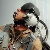
Some more work. It is very easy to get bogged down with adding detail to these big models, so I took a small break from it and did some other projects, hence no progress for a while. I intended to have this model finished by the end of the year so had to get a move on. There is a considerable amount of detail missing from behind the seats so a lot of extra work has gone into detailing those areas. I used the AMS parachute packs and scratchbuilt everything else behind the seats. As can be seen in this excellent pic of Graham, you can pretty well add an unlimited amount of detail behind the front seat. Another opportunity for extra detail on the kit is the nose gear leg. This is quite visible and can do with a tidy up. the torque link is just a lump of plastic and does not have a good representation of articulation. I carved some detail into the link and separated it to show the articulations. The back side of the stock leg. I carved out the pivot point between the oleo and the yoke.5 points -
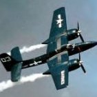
I've got the fuselage closed up (May I say right here the fit of this kit from the 1970's can shame some modern kits!) the left...port side? engines are faired in and nearly done, with a bit of panel scribing and repair needed as yet. It looks from the pictures to be a pretty good fit (going by the small amount of filler?) but there's a few hours of sanding so, looks may be deceiving. Right side fairing in is underway. Thanks for looking!5 points
-
I have a major distraction from large scale planes going on, being this Ferrari GTO 250 from Model Factory Hiro. I think it does qualify as large scale, and the real thing costs more than a small aeroplane, with the last one going for around US $ 48 million. To my mind it is one of the most shapely and attractive cars ever made. There are not many WIPs of these examples, so I thought I'd give it a go. The kits themselves are horrendously expensive, but are incredibly well detailed. I also have a classic Pocher 1/8 Alfa Romeo in its box waiting to be built, but the MFH kit wins hands down in terms of accuracy and fit. I have got this to completion of the engine, but won't be taking it much further at this stage as we are relocating from Australia back to New Zealand shortly. The model comprises of the major body parts being formed in white resin, with the bulk of detail parts being in finely cast white metal. These are complemented by two large and one small etched stainless frets and a large number of very nice plated metal parts, wires, tubes etc. The spare wheel is made up from cast parts, whereas the main wheels all require building up with stainless spokes, turned hub parts and plated rims. The detail is nothing but stunning, although I am still not sure that I am Zen enough for the experience of building the wheels. I'll use the rest of the kit as practice. My early lessons in my work on this so far are that the kit instructions must be studied extremely carefully and on any one part you need to be looking several stages ahead to check for any fit details. Unfortunately the instructions are not quite as clear as they could be, but that is more a reflection of the sheer complexity of the kit. The many hundreds of tiny white metal parts all need cleaning up and often require relatively minor work to fit perfectly as originally designed. Because of the amount of detail included, there is absolutely no wriggle room in terms of fitting all of the various assemblies together. If they do not fit perfectly, then there will be trouble later! But, before even starting, delving into the big red box revealed all of the white metal parts wrapped in layers of plastic wrap in one bundle spread across the bottom of the box. Unfortunately I didn't photograph it - it had the appearance of a mass of metal cobwebs! What I did photograph is the end result of many evenings spent sorting the parts into small bags labelled with the relevant instruction step. None of the parts are numbered, and some were a real mystery until the process of elimination identified their place in the scheme of things. There are still a couple of pieces that I have yet to identify - and only one small missing part which was quickly set right by MFH. The only aftermarket I have got are seat belts, scale pipe clamps and some tiny pipe fittings for some of the oil pipes. I had decided to build this as my representation of Chassis # 3757, which has belonged to Nick Mason of Pink Floyd fame since the late 70s. This choice is mainly because it is surely the most photographed example. I even have an entire book, almost all of which is devoted to this particular car. Plus I am a Pink Floyd fan. The kit includes markings for "White 22", but the model is a curious mix of the car as raced in 1962 and some later changes made to her. I will model the car as she appeared about the turn of this century. it will include the three cooling vents behind the front wheels and an oil cooler above the rear axle, but will be before the two rows of cooling slots were cut into the bonnet. This particular car also had the bolt on rear spoiler, as originally fitted, replaced by the later faired in version, so that also must be changed. One of the small number of inaccuracies in the kit which I have found are the cooling intakes below the nose. They are modelled too far back from the front and, as a consequence, are formed too shallow so as to avoid fouling the radiator as they sit directly beneath this. In fact they are located very close to the nose and direct air to the radiator. So the first job was to take a wonderfully molded resin body and cut into it. The new intakes were formed from plastic card and then glued into a rectangle cutout made in the resin body. I made a template for the cutouts in paper as the shape was not a simple one to cut directly into plastic sheet. the gray area is where i hadn't managed to superglue the rectangular insert in perfect alignment with the body and had to use filler to smooth the join. GT 3757 has an L beam across the rear of this panel, presumably as a stiffener. I replicated this with a piece of brass L section. The cooling intakes are still not quite as close to the front of the bodywork as they are supposed to be, but to bring them any closer would have required a total rebuild of the nose, due to the way in which the piece has been formed. This I was not prepared to do as I would surely ruin a perfectly shaped nose. The other body changes were smoothing in the rear spoiler with the surrounding body work, cutting an extra cooling slot behind each of the front wheels, rounding off the corners of the remaining cooling slots and extending the spar wheel storage shelf to the rear of the body shell. The cooling slots , which had squared off corners as provided, were rounded off using superglue gel, but will no doubt require further work when eventually primed. I think these also had panels behind them as "gills" which will need forming from plastic card. I will post the work on the engine later, and then there will be a break until the model reappears across the Tasman. Cheers, Mike4 points
-
Just finished phase one of the re-scribing on the left fuselage half, then cut out the full length of the bomb bays (26.4 cm). The reactor needs one coat of primer then silver paint. It's taken a couple sandings/primings of the reactor to remove the 3D printing artifacts.4 points
-
Howdy folks, Brian Leitch takes a look at Doyusha's latest release of its Willow kit: Doyusha Type 93 Akatombo Advanced Trainer - K5Y2 "Willow" Thanks, Brian! And thanks also to HobbyLink Japan for the review sample. The kit can be purchased from them at the following link: 1/32 Kawanishi K5Y2 (Willow) "Akatombo" Seaplane Kev3 points
-

Lancaster B.II
scvrobeson and 2 others reacted to Royboy for a topic
Do it anyway, the result would be you'd get one before anyone else! Good luck!3 points -

Dragon/ Cyberhobby 109E
thierry laurent and 2 others reacted to nmayhew for a topic
Yup that’s pretty fatal right there. I’ll PM you my address so you can send me the kit.3 points -

STRIKE TEST TOMCAT
Starfighter and one other reacted to Collin for a topic
I swear, I am doing a large scale plane next. Want to get this project done so I open the display case only once to put in this build and my recent EA-6B build. Tamiya 1/48. OOB, but out of a few boxes since I have to use parts from the D kit to make a late A. This will be Salty Dog 202 in the end. OOB cockpit, Milliput seatbelts. URL=http://smg.photobucket.com/user/tatuskocs/media/DSCN8726.jpg.html][/URL]2 points -

Tamiya 1/32 F4U-1 Birdcage Corsair - Done!
Starfighter and one other reacted to Brett M for a topic
A little bit of progress today. Just worked on the cowling, armored glass and gunsight. Nothing big, but at least a step forward.2 points -
They're actually one of our sponsors! And produce a fine range of inter-war kits. This is their first entry (that I'm aware of) into WWI subjects. Kev2 points
-
Stencil cutting material?
D.B. Andrus and one other reacted to Out2gtcha for a topic
Prior to finding out about the pre-tension issue with the giant rolls of Ora-mask, I actually purchased the end of one of these enormous rolls, that had about 200 - 300 ft of Ora-mask left on it. I took it to my local FedEx business office that had a office supply workshop with a 6' long straight edge cutter. The roll was 24" wide, so I cut strips 12" x 24" off the roll, then proceeded to cut those 12" thick strips into 3 8" x 12" sheets. I spent probably 3 or 4 hours in that FedEx shop that day, and cut enough sheets for myself for the foreseeable future. I took the 12" x 8" sheet home and stacked them neatly in my office. After I got home that day, I experimented with the sheets I had just cut, and made several mask cuts including a full checker board for an upcoming project. Several of those sheets I cut down to 1/2 their original size, and cut some of those with masks too. I made the mistake of taking the checkerboard downstairs with my to my work shop, as I was going to see how well they lined up to the base I wanted to use. The mask cut of the checkers was perfect at the time, 100% nearly impossible to see the cut lines. I made the mistake of turning on my portable heater in that room that night to accelerate the drying time of a model I was working on..............I made a second mistake of leaving the full checkerboard sheet in that room overnight. A few hours later in the morning I went to check my model, and noticed that ALL the checker cuts had shrunk so badly away from each other, that there were now 1-5mm gaps between all of them. I took the rest of the sheets I had experimented on and placed them in my basement where its cool and dark. Now months and months later only some of them have started barely shrinking away from themselves. There really isn't anything that helps the pre-shrunk tension in the Ora-mask other than keeping it in as cool and dry a place as you can find, and cutting the masks as close to the 11th and 3/4 hour as you can. The shrinking issue follows the sheet to whatever size you cut them to unfortunately.2 points -
Hi Tony, Ha Ha! ....Yep, Feather one minute, Sledge hammer the next - that's definitely my modelling style. Materials? Some local ( AUS)... some overseas... Ebay is a good source - long list of other suppliers - msg me if needed. Weight? strangely no. Apart for the odd bucket of nuts & bolts I've been using , I try to use alloys/plastics/copper in the accessorising/mastering parts of the build. Mind you- these parts will be converted to resin later , so what- ever weight there is in the mastered original parts right now - will be lessened later on in resin copies ( except for metal landing gear and the wing / fuselage structures) Pip2 points
-
This could be irresistibly cosmic. Tony2 points
-
Love the combination of detail finesse and brick sh**-house construction turning a flimsy vac into something more robust. I was getting through so much expensive plastic strip etc extending and beefing up just a fraction of a Tigger Su-15 Flagon (although it'll be great, one day) ; where do you get the extra materials from, and is weight an issue? Great work Pip Tony2 points
-

Dragon/ Cyberhobby 109E
Rick Griewski and one other reacted to MikeMaben for a topic
While messin' with my D-1 conversion ... I discovered a fatal flaw. There's a panel line missing on the port side of the fuselage. I have 2 -3s a -4 and a -7 and it's missing on all of them.2 points -
Tamiya 1/32 F4U-1 Birdcage Corsair - Done!
Anthony in NZ and one other reacted to Brett M for a topic
Thanks everyone, I appreciate it. Definitely feel the headrest looks better with the stretched sprue added as well. Plus, it looks better than the rectangular headrest, IMHO. Progress may slow even more now. My wife found a much faster route down the stairs yesterday and broke her wrist, so bench time may be limited to short spurts. She may need surgery to repair, so time spent away from the bench (and work) will be at an ortho surgeon's office! For now, I've started on the glass on the instrument cowl as well as painting it with MM Interior Black. Montex masks made short work of protecting the clear areas and were much nicer than cutting out the Tamiya masks. I plan to also spray some Tamiya NATO black to replicate the rubber bumper edge that I see in pictures...... Pictures.....tomorrow? We'll see! Hopefully some time to spend in the hobby room!2 points -

1/32 WNW Sopwith Pup
D.B. Andrus and one other reacted to kensar for a topic
An update to catch up with the build: I replaced the kit detail with some more realistic parts - spokes and valve stem. Weathered wheels. Wheel hubs were turned out on the lathe. The ends of the LG axles got some thread bungie cord and metal retaining pieces. Test fit of the wheels. Weathering will begin soon. Thanks for looking.2 points -
hello again so while I can't fit them yet, I wanted to get the flaps built up.. I used the same principle as the ailerons in that an inner core with raised rivets was made and then skinned with panels with normal rivets - you can see the raised rivets on the trailing edge in this shot... ..the first thing was to get the drawings into the overall 'folded out' shape along with the rivet markings - the raised ones are in threes along the trailing edge. there are also cutouts & shapes along the leading edge which curves under the wing trailing edge.. ..I always work in pairs if twothings need doing, so I don't do one and get bored doing the other, so bothe were made and folded.. ..the drawings actually had me confused as they show the lines of lateral rivets in paired rows, but all the pics I have show just one row so that was what I went with - here are an upper & lower pair for the panels with recessed rivets - the bottom one has just been done, the top one already burnished out to get rid of the 'pillowing' effect of the rivetting process.. ..the structures were strengthened with thick card and an inner core made up to define the profile and stop sagging.. ..details added and taped up ready to paint YZC where needed.. ..then the rivetted panels were added - here tape acts as a hinge at the top, and is masking where the impact cement goes at the bottom.. ..after painting the details showed quite well - I also noticed the curved edge that goes under the wing is normally seen quite glossy, I guess it doesn't get as much exposure as the rest of the structure, so I polished this area.. ..I also worked up and fettled the wing & fuselage so they fit and painted the recess YZC ..the aileron detail can still be seen.. ..not at the right angle or fixed yet, but you get the idea.. ..and that is the flaps nearly done - I will finish the fittings when I fit them .. ..I have the 3D printed wheels & hubs I designed from Tim Perry now, so they are next to take a look at TTFN Peter2 points
-

HK B-25H
Whitey and one other reacted to machine_marty for a topic
A bit more progress. decided to mask/spray the mouth using the decals as a template for masks on my cutter. Came out better than I thought, so happy with that. I've applied a pin wash all over (photos to follow), and then it's just a case of putting it all together. Thanks for all the generous comments2 points -
1/32 Hobby Boss B-24J Liberator Assembly Ship Tubarao
Daniel Leduc and one other reacted to monthebiff for a topic
So a little more work done over the last few days, first up I built up the bomb bay assembly, not to many parts really but some care is needed in getting everything square but the close fit of parts does help. In general I think the interior is pretty good on this kit, however I do think the bomb racks are very very clunky and poorly done but not a lot will be seen when complete. I believe Eduard make a couple of sets to replace a lot of this but its an expensive upgrade to be honest, I do think when its all painted up and closed up nobody will really notice to much as its hardly like a B-17, Lancaster or even a Mosquito for that matter with big wide open bomb bays showing everything off. I've also test fitted the whole interior in to the fuselage before moving on to adding any further detail and the fit is very good, here are a couple of shots. and a quick shot of the cockpit opening. I've got a good picture on which direction I'm going on this now and which area's to add further detail to. The nose and waist areas will get the main attention from here now. Regards. Andy2 points -
Normally no, but I'm going to display it with the reactor in the process of being winched up into the aft bomb bay, so it will be visible.2 points
-
Pete - I made the pulleys on my lathe. Some general progress... Moving to the top wing next. Thanks for following along and commenting, everyone. Ken2 points
-
It's tricky to figure out where to cut the nose of the bomber off. The available diagrams and photos don't seem to agree on this, so I picked one and started cutting. I found if I cut the radome off first the fuselage will fit snugly in my miter box (or mitre box, depending on which side of the Atlantic you reside). Lucky! The cut still came out a bit crooked because the fuselage radius is slightly larger than the height of the miter box. After cutting you need to sand off some raised features on the inside of the fuselage halves. Then the test fit of the new nose from Click2Detail (https://www.click2detail.net/) Deciding where to cut the bomb bays open is another guessing game. Here are the end points I decided on, and also the center point where a bulkhead will go between the two bomb bays.2 points
-
Thanks Jack and Ben - your kind words are very appreciated! ( AND Thanks everyone for the 'Likes' ) Front fuselage structure : My focus now is the flooring / Back wall , and Front wheel well areas. I must construct and design the 3 areas to connect together as the following drawings and photos explain.... The red areas above , I am working on - in terms of design /fit / detailing ( rivets etc) and construction of individual parts... The common areas are that everything 'hinges off' is the back wall of the cockpit ( more of a reinforced station or bulkhead of the fuselage ) as ... 1/. the front is pressurised and the flooring is attached to the rear cockpit wall 2/. the back of the wall is really a fuselage bulkhead sealing the front of the fuselage to the bombay and also must carry .... 3/. the front wheel well and the landing gear structures ( which includes the weight of the aircraft) as well as absorbing the forces of landing.... The problem is : as shown previously .. the front landing gear mounting points are to the front of the wheel well - which is also part of the rear wall bulkhead. So I must incorporate the front wheel well attachment point to the rear wall bulkhead as one molded piece. First I must enclose all open areas in terms of molding processes... The piece to the right ( above) must be merged or incorporated into the rear wall / Bulkhead This piece must be square and also needs a tidy-up before the next process..... I have made and incorporated some bracketing pieces to make construction of the individual parts more easier for everything to line up and go in it's proper places - as it should.... The red arrows show the alignment strips, so that each parts simply clips in place " Like so! ".... Now we move to the other side of the rear cockpit wall/ bulkhead to the inside back cockpit wall for rivet detailing..... starting with photo references... From this 'Base' I can begin with detailing cockpit.... wish me luck ! Pip2 points
-
I'm replacing the molded-in detail of the aileron pulleys. Getting on with the general painting and decaling.2 points
-
RAAF special occasion Mirage buggy FINISHED.
scvrobeson and one other reacted to ericg for a topic
Thanks guys. Yes it is yellow as per the tug. Some more work. I finished the tractor, weathering it a bit more than I would like, but it has added a lot of character to the scene. I also scratch built the searchlight on the bonnet. One of the challenging aspects of this build has been getting the straps securing the buggy to the trailer right. I scratch built the hook and ratchet assembly from plastic card. As I needed a couple of these, I copied them in resin. A thin strip of Tamiya tape makes up the strap. A test fit of the strap. I painted one and rolled it up In the photo of Sean, it looks as if there is something in the stowage basket on the rear of the tug, whilst I can’t prove what was in there, I thought the rolled up strap might look pretty good, as if it has been chucked in there in case the buggy started to fall off. I glossed up the buggy in preparation for the decals, using simply THE BEST clear gloss I have ever used.2 points -
I plan to paint this model in the newer all over grey scheme with Three Squadron markings. It will make for a reasonably boring jet as I don’t plan on having anything hanging off it yet in the way of ordnance. My good mate Peter sent me some excellent clear photos that he took of an F-35 parked at the Australian International Airshow held recently. This jet had really cool exhaust and intake bungs installed with colourful 3 SQN logos painted on them and they will add a great splash of colour to the jet. Now, I dont usually like putting these things on my models as any good jet modeller will go the hard yards to sort out intakes and exhausts which are usually amongst the hardest part of a jet model. I reckon it is a way of chickening out of that part of the build but in this case I will make an exception. Here are the pics (with permission from Peter, thanks mate!) I am am not aware of the existence of the bungs in this scale so have set about creating my own. Due to my experience gained with the nose art on my Boomerang build, I will be creating spray masks for the logos painted on them. I cut out a circle of thick plastic card that fit into the exhaust pipe. A suitable quantity of Tamiya epoxy putty was mixed to form the area which I would be sculpting The putty was stuck to the plastic circle and shaped to fit it, then smoothed over with Mr thinner painted on with a brush. Not sure why the scissors are making an appearance here. I used various tools to sculpt the ripples in the surface of the bung and scribed a line around its edge as per the pics. Primed, smoothed, primed again...... Should look great painted. I will add the pull handles after this process.2 points
-

Another Felixstowe, (Just to keep the first one company).
MikeC reacted to Bradleygolding for a topic
Okay. Time to fess up. I started this a month or so ago. It's my first WNW kit and my first serious use of Acrylic paints. No airbrush either, but did use a spray can for the clear coat. Steve1 point -

Lancaster B.II
alanash1963 reacted to reconspit for a topic
Hey, does anyone know, if there is a Lancaster B.II with radial engine is planned? Or a conversion? ...before i hack 2 Revell Beaufighters...1 point -
1/32 Hobby Boss B-24J Liberator Assembly Ship Tubarao
Anthony in NZ reacted to monthebiff for a topic
Nice idea Anthony and wish it was that easy as it needs to be a bulged window so should be interesting!! Regards.Andy1 point -

1/32 Hobby Boss B-24J Liberator Assembly Ship Tubarao
monthebiff reacted to Anthony in NZ for a topic
Nice work Andy! Just a thought, I would probably put an oversize square piece of clear in the fuselage and polish it up. Then spray the window with a circular mask....? Keep up the great work1 point -

1/18 P51C Mustang "Lopes Hope the 3rd"
daHeld reacted to geedubelyer for a topic
Watching this come together is astonishing but extremely entertaining. Thanks so much for taking the time to share every step of your progress Peter. It's much appreciated. Cheers.1 point -
my newly Tamiya 1/48 Me2621 point
-

F-117A • Nighthawk
Jan_G reacted to F`s are my favs for a topic
The adventure with the side frames of the cockpit. OOB they are just long clean pieces of plastic... That's how they look like in the real plane: I made provision for the canopy handle and for this huge black knob in the pic above, then I glued another stripe of plastic with the same thickness undernead and sanded them. The two cooling tubes that go into the frames are also added while the cooling grids will be easier to add after the painting - with just thin stripes of tape... and it is so much better now. Still not painted though.1 point -

1/32 Trumpeter Sukhoi Su-25 Frogfoot *Completed*
scvrobeson reacted to BradG for a topic
Managed to get the rest of the camo on tonight. Just masking up various other parts now. Still got landing lights and a few other bits to put on and of course the weapons.1 point -

Vietnam Hun "nashville sound" FINISHED
AlbertD reacted to blackbetty for a topic
started to add some PE in the wheelwells and on the wings1 point -
Article on Lou IV colors...
Rick Griewski reacted to nmayhew for a topic
reading that now is as confusing as when i first read it as much as i stare at those pics, I just can't see any blue maybe has something to do with being colourblind lol1 point -

Aviatik 'Berg' D.I
109 reacted to sandbagger for a topic
Hi all, The engine is now completed. I've added the ignition leads and spark plugs, timing mechanism, oil filler caps, water pump and coolant pipe, vale levers and springs and carburettor lever. I've also made the exhaust pipes from 1.8 mm diameter brass tube mounted onto 1.4 mm tube - the kit items had 'solid' bores. Test fitted into its mounting frames. Mike1 point -
The trailer was next to be finished. I added some extra detail to it, which I was almost about to leave off. This particular trailer has a handbrake system fitted which is visible under the deck between the front and rear wheels in the picture of Sean posted earlier. There is a small hand brake lever under the front of the trailer, connected to two wires that run to disk brakes on the rear axle. If it hadn't been for Max's excellent photos, I would have had no idea how this was all supposed to look! I added a number plate which is also visible in the reference pic. I have a special no. picked out for it which will be placed there once I get the decals made up. This was a tough little bugger to make but certainly worth it in the end. The status as it sits now. I am waiting on the decals, and just need to do the straps and it will be done!1 point
-
woodgrain done with oils A little chipping also... loading up the gun... Still slogging through the general painting.1 point