Leaderboard
Popular Content
Showing content with the highest reputation on 07/24/2021 in all areas
-
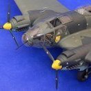
Short Sunderland MkII
Sharkmouth and 8 others reacted to tomprobert for a topic
Cheers, Rich - and yes I'm a frequent visitor! Howdy folks, I've been busy working on the stabilisers of the big Sunderland of late. As usual, the first job was to scribe on the panel detail: I did contemplate removing and scratch-building the elevators, but there is some really finely moulded rib detail that is actually well worth keeping. I'll need to add the hinges and with a dark wash along the hinge line when painted, I think they will look fine. Each section was cut from the backing sheet and sanded to shape, ensuring the correct depth and thickness. As you can see, the fit was pretty good when test-fitted: Given the fact that the stabilisers are likely to get whacked periodically during the remainder of construction, I wanted them to be nice and sturdy so I have added a plastic card spar, as well as the usual scrap sprue treatment along the leading edges. I've also opted for a brass tube spar system that will fit through the fuselage and offer a really strong set up: The stabilisers were then trimmed carefully and added to the rear of the fuselage - careful consulting of plans ensured they are in the correct position: The careful trimming of the mating surfaces, along with the spar structure ensured only a lick of filler was needed along the fuselage to stabiliser join. She's starting to take shape now: She lacks a bit of stability at the moment, so I better get cracking with the fin... Until next time, Tom9 points -

Fw190 D-9 | 1/12th scale scratch build replica
HerculesPA_2 and 8 others reacted to 109 for a topic
Next are the Gerätebänke or side consoles in the cockpit. Proved to be more tricky than expected including researching the exact geometry. I hope I have it right so far. I started by making paper templates and a styrene template. Then I cut some 2 mm MDF and made the final one. White styrene strips were used for final adjustments to make it fit properly.9 points -

RAF FG.1 XV571 WILD HARE Phantom Conversion
Spooky56 and 8 others reacted to Anthony in NZ for a topic
Thanks as always @Derek B Well i have to admit to a bit of burnout here. Correcting and replacing surface details on this right hand side is mind numbing and hard to motivate myself to carry on with all those rivets! Anyhow I have still done a little bit each night and the Phantom builds here have been hugely inspiring, thanks guys. I put my head down today and tidied up some more areas at the back end where the resin and plastic join (from where I earlier cut the conversion fuselage into 3 sections). only a couple of panel lines to do now and continue working on adding the fasteners. Then I can do the rivets. I will leave the best part of this post until the end as it's the main reason to update you all because I dont really have a lot to show from spending hours on the surface detailing. Here are some results of all my fine tuning, see nothing really looks different, but I really hope it pays dividends with the final result Then as a bit of a side track for me was to take a look at the lower nose profile and how I was going to fix it. I added some thick plasti card to the front, more on this later) and removed a couple of antennas that are not present on Brit Tooms. A suitable section of the original Tamiya fuselage section was cut out of the back for the Aux air doors in the back. Still yet to add some surface details before I make them too thin and add a bit of internal structure Anyway the big news and main reason to post is this......... Kerry said, well I made a 'Hot' section, I may as well make a 'cold' section!!! Isnt he awesome! He said to me that the NZ IPMS Nats are coming up on 8-10 Oct in Auckland where he lives, so I am going to see if I can finish this beast up to take up there. I will do my best and it gives me a target! I probably wont enter it as I have let my membership slip for quite a few years and I am not into competitions or placing anymore (I used to judge them as well) but happy to bring it up to display if nothing else Thanks for looking all, and until I have more to show.... Cheers Anthony9 points -
Hi all, I decided to join the subassemblies of the rear upper deck and the seat rails-armor plates. After careful aligning these parts for some 30 mins. I joined them with a few drops of Loctite 480. After that came some cleaning up, de-greasing and masking/airbrushing RLM 66. I settled on RAL 7015 for RLM 66, it´s not too dark which would absorb too much light in the cockpit tub.8 points
-

Revell Bf 109G6/R6 1/32 Pilot Gottfried Weiroster
Wolf Buddee and 5 others reacted to Gazzas for a topic
Thanks to a few words from Kais, and finding that my original plan wasn't going to work, I cemented the card fillets to the bulge sections: Then I test fitted, pulled apart filed and sanded... re-test-fitted... pulled apart again... until I finally got it to the point where I reckon I can call it good. It's quite a funky wing design. The kit has some nice engineering features... that are a PITA when it comes to getting stuff right. YOu have to do everything in perfect order... you can't reverse the order of parts going together. Anyway... with that done, I considered cleaning up the parts... filling behind the card with black CA and then sanding it all smooth and continuing with assembly... but then I had a second thought... I need to prepare for the WfGr 21 rocket tubes and mountings before I get the kit too far along! I'm not one to seek perfection when I know it goes beyond my abilities and supplies. Basically what I did was use some photos of an Eduard set, and use them to help me 'engineer' the parts I came up with. So, I had to take pictures supplied by friends with the Eduard AM... resize them to meet the parts I've found and do a little math to tell me where to drill. The intersections of tape mark drilling points in the polished aluminum tube. The mounting brackets of the rockets will be .5mm rod enclosed in .7mm tube. This way I can space the parts to imitate detail. Here, the tube and .5mm rod are held in situ by blutack. I'm not sure of the angles, but I'll fiddle with it some tomorrow. I lightly sanded the tube to give the primer something to get hold of. The prospect of trying to work around these tubes is daunting as there is little, fragile detail to add to the wing, yet... and then there is all of that other assembly and weathering to complete. Thanks for looking!6 points -

Henschel Hs-129B-2/RIII - Finished
Greg W and 5 others reacted to Dpgsbody55 for a topic
This is my first ZM kit, and it won't be my last. I also have a DO-335 in the stash but I'm looking forward to their BF-109 and FW-190's too when these are released. This kit is very well detailed and the parts fit is excellent too. Definitely gets my recommendation. Thanks Tim. The kit really lends itself to showing off some of the details and it's not that difficult to build. Just follow the instructions, which is something I'm not good at. So you could be excused for thinking I've been asleep at the wheel on this build, and indeed I have been. Not a lot has been done these last two weeks in part because of a now fruitless search for a car to re live my youth and tinker with - one with chrome bumpers, if you remember such features. My first job after the last update was to add the ailerons and flaps, then add all the panels that close up the guns and other fuselage openings. In the end, some of these just kept falling off, so I glued them into place as they don't show much anyway. Also, I'm sure they'd fly off into the never never as soon as I pointed an airbrush at them and I'd have paint in the wrong places and missing hatches. Some, however, will be removable. The ailerons and flaps are attached only by their actuating hinges, two for each flap and four to each aileron. I've also placed a masked canopy in position and painted the cockpit colour to represent the inner side of this part. And forgotten to take photos.... I've also been pondering the paint on this, as looking at Humbrol's idea of sand gelb left me increasingly concerned about it's authenticity. I also needed to ponder how to use an alternate colour considering I need to get it around other painted parts. In the end, I've managed to brush paint some Tamiya XF59 in and around the engine and exhausts by cutting a piece of paper to size and holding it in place while I poke a paint laden brush under and around the exhausts. Here it is with the engines and nacelles masked off as I'll be painting soon and still haven't fitted the cowlings which don't fit because I didn't follow the instructions. I've also built up the MK-103 30mm cannon which will be mounted to the underside and unfortunately covered. Would you believe that there's eleven pieces in this?? Here it is placed, but not glued, into position. You'll also see the ailerons and flaps and how these attach. The last shot shows the last few remaining items that need to be attached before painting commences; a long aerial, even longer pitot and the landing light fairing which will have the reflector painted in and lens attached after painting. That's all to report at the moment. The next stage is to break out the airbrush and start painting this model. It will be sand gelb (yellow) with green splotches and blue undersides with the usual Luftwaffe white desert markings. Incidentally, I'm fortunate in the masking in that there's no green applied to the real thing around the exhausts, hence the exhausts being fitted now and masked off as they are. Cheers all, and stay well. Michael6 points -

HK B-17...C 5/4 sweating the metal
Derek B and 5 others reacted to brahman104 for a topic
.....and a 5 axis CNC machine would be pretty handy too! Yes the current house is definitely not big enough for even this one, but one day..... Again one of those little updates where you don't have much to show for a whole heap of work. I realised that before I can build and install the rear entry ladder, I needed to do the window behind it and, while I was at it, the two radio room windows. These should have been kit parts, but after 7 years and an international move, they are nowhere to be seen...... I'd had good results on the nose with gluing in a an oversize piece of acrylic and filing/sanding back to make it flush with the fuselage, followed by hours of polishing... Very difficult to photograph a window it seems, especially if you've done a reasonable job of polishing them The first two are "in progress" And the last is the final result... There's still some very fine scratches in them from the sanding process, but I'll go over them all again along with the nose ones prior to starting the skinning. Unglamorous, but necessary work to enable what comes next Cheers, Craig6 points -
I think this is the final post on the cockpit for a time. I have completed as much as I think I can without assembling the fuselage pieces together, at which time I can finish up those components that cross the boundaries (quite a few). So this post describes the flare pistol installation and the cockpit heater installation. They can be seen here: Note the pilot seat is missing in that picture - these components are not going to be that easily seen in the end. So it was on with the flare gun installation. This cute little thing is the AN-M8 flare pistol - something that maybe all American aircraft of this era had: There are lots of pictures of this item on the web. That and the Vought installation drawing (obtained from Aircorps Library of course!) left little guesswork. Here it is with it's bracketry on the RH side of the cockpit sidewall: Note the tube that extends down. On the real aircraft, this tube connected to a fabric covered flush penetration in the lower fuselage skin. When fired, the round would exit that way. Note here that the exit hole, if I made it, would be on a different part. One more example of a component that crosses boundaries. Many of these cross-boundary items pose big challenges for me, as I have said before. However in this case I will not reproduce this penetration because it cannot ultimately be seen. So no big challenge. Next on the docket was the cockpit heater installation. This unit at first (on birdcage versions of the Corsair) was under the instrument panel, but somewhere along the line relocated to be under the pilot seat. And that config is what this aircraft gets: The "hose" is the insulation covering from a 12 gage household wire. Note that the "hose" passes through a lightening hole in the (flimsy) foot trough bracket - just like the real thing. Had to be very careful. Integrating that, for me, was a major victory (well partly - read on). I had been brooding about that very thing for months. FYI, that hose in real life goes to a defroster unit under the windshield coaming. The heater box is simple plastic sheet, and simplified some. It just will not be seen enough to warrant more effort. The black elbow on top of it is a chunk of .25 by .75 evergreen plastic block, dremeled and filed into shape. The heater box support bracket, as can be seen, slightly overhangs a boundary - once again. But not much of a challenge. So it was time to dry fit the RH and lower fuselage and see how it's going: Compare that to the first picture of this post. Another shot without the labels: You might think I am thrilled. I am not. About the time weeks ago when I installed that large electrical box you see there behind the hose, I suspected at that point that the right hand rudder pedal was going to clash with the heater hose, and indeed it does - in a big way: This clash prevents the rudder pedal from assuming the same position as the LH pedal. Unacceptable. Why did this happen? Well it's simple. This is an example of heavy gages on the model affecting the integration of the cockpit. Something we all deal with from time to time. On the actual aircraft, clearance is tight in this instance - it's obvious from pictures. I have not decided what to do yet, but it seems clear that the hose has to go. At least locally. I will probably cut a section of it away just forward of where it penetrates the foot trough bracket where it passes along the electrical box. Just enough to clear the rudder pedal. And hope it isn't very visible. This little abomination will hide behind the foot trough and be deep in shadows. So maybe no big loss. So guess what is next! Landing gear bays! As I have repeatedly described ad nauseum, in order to finish the cockpit and do other fuselage work, the center wing has to be done first. So here we go: All the molded features in the bays must be dremeled outa there: Look at all those posts meant for screws that fasten the upper wing to lower wing. It's going to be an adventure. First will be making and installing the spar segments. See ya later.6 points
-
Happy Summer All Many thanks for all the kind and thoughtful comments. Things here are progressing. It was decided to go back to the cowling assembly which, turned out to be more challenging than I thought it would be, especially the nose piece that closes the front of the cowling. It took a couple of days of sanding (very carefully) filling, and test shooting. The curves on the nose frontus closure is very subtly curved in several directions with the area directly behind the spinner sitting forward (raised) in front of the rest of the nose. You can see what I mean in the photos. It took five iterations with very small adjustments in between(one missing in photo). The last (far right)to get to the last one. Three were made from .020 card. One made from .030 card.. and the last from .040 card. Getting the curve under the spinner seat and the smale radius on the chin where it meets the cowling were the biggest challenges. From there, it went to the fairing that sits between the fuselage and the rear of the cowling. I might reshoot this part. In hind sight, it might have been better to just leave the fuselage a little long and try to sand the needed radius into it rather than making a separate piece. The end result... So is the state of the ST-A. Maybe a spinner next and revac that fairing. I hope everyone is enjoying their summer and enjoying good health...Be safe. Best Geoff4 points
-
Hi John - I know it's a lot of "unknowns" for the nose/radome configuration on the actual Bolo flight. Note that even the standard radome with the IR sensor fairing (aka the donkey dick), prior to the APR-25 RHAW installation, was fitted with a short, dummy (empty) IR-sensor cap, which was 2"-3" shorter than what became the standard RHAW antenna fairing for all USAF Cs and Ds after 1967. When the RHAW was installed, that round cap was an extended version of the factory blank cap installed where the Navy IR sensor was meant to be mounted. Jennings's first illustration, "B," has the short cap (and a smooth vertical tail surface above the rudder); while the later, "Aug '67" illustration "L" from your earlier post, has the longer RHAW cap, as well as the acorn antenna above the rudder on the trailing edge of the vertical tail. We really have no way of knowing how 7589 was configured on 2 Jan 67, during the Bolo mission. It reasonably could have been any one of those three nose radome options. The 8 TFW seems to have been using "slick" radomes without the IR sensor fairing as temporary replacements for aircraft that needed their original radome repaired or replaced; and potentially while the primary radome was getting fitted with the APR-25 RHAW antennas. Any photo on one day showing a slick nose could have been instantly out-of-date on the next day, when the radome was replaced with the new RHAW system...it seems that those configurations were changing that fast. When looking at August '67, however, those configurations were more stable, and nearly every F-4C in Thailand and Vietnam (Cam Ranh Bay and Da Nang) had been fitted with the RHAW radome by then, as well as the USAF-standard "curved" inboard pylons with the MAU-12 munitions rack. Note also that by Aug '67, the 8 TFW was quickly re-equipping its squadrons with F-4Ds, and the remaining C-model airframes were shuffling through the 497 and 433 TFS (the last two squadrons to convert to the D) and getting transferred to the 12 TFW at Cam Ranh Bay, or back to stateside units. I think by late Nov/early Dec '67, all the Wolfpack's C-models had been transferred out, and they had established four squadrons with F-4Ds: the 555 TFS, 435 TFS, 497 TFS, and the 433 TFS. The 12 TFW at Cam Ranh Bay, tasked primarily with CAS missions within South Vietnam (and later, interdiction missions over Laos and Cambodia), stayed equipped with F-4Cs through at least 1970, while the 366 TFW Gunfighters at Da Nang re-equipped with F-4Ds at the same time the 8 TFW Wolfpack did, at Ubon.4 points
-

Wolfpack Phantom - 8th TFW F-4C
Jerry M and 3 others reacted to oppenheimer for a topic
I just used Red Fox panels on my F-4C, they are great and gives life to the cockpit 100%, quinta studio is taking too long to release the 1/32 version of the F-4C my pit with aires ejection seats4 points -
Disclaimer - this is going to be a very long project. I've got other irons in the fire and limited modeling time. This is just my introduction to the upcoming build. Of course I'll be using the Tamiya 32nd F-4C/D kit, along with a (surprisingly) large amount of aftermarket bits. First off - my subject. I have never much interest in the Phantom from a modeling standpoint and zero interest in the F-4C version. The C just seemed "dull" compared to the colorful Navy jets and the later, more sophisticated Airforce D and E models. That changed when I happened to take a look at Fundekals downloadable instructions for their latest release - F-4C MiG Hunters - Operation Bolo and Beyond. As with all of their decals, the instructions are absolutely amazing. They really qualify as a reference booklet, much more than just "Apply decal X here" that most aftermarket outfits provide. I highly recommend you grab a cup of coffee or your favorite adult beverage and give them a read. They can be found here: https://www.hobbyzone.biz/fundekals/docs/fun_32011.pdf Once I read through the instructions, I became fascinated with these jets. Aside from their history (and that of the 8th TFW "Wolfpack" and their legendary wing commander, Col. Robin Olds), what really blew me away was the absolutely insane variations in markings, paint jobs and weathering on these Phantoms. From a modelling standpoint, I am drawn towards unusual, non-standard subjects. The majority of the jets in the Fundekals set were early F-4C's, which started life in the USN standard light gull grey over gloss white. Once losses started to mount in SEA, there was a crash program to camouflage all tactical jets in the now famous SEA scheme. These early jets were mostly painted at repair depots in the Philippines. These early paint jobs weren't exactly per the USAF specification. The gloss white undersides, with all the Navy stenciling, were left alone (the AF spec requires FS36622 camouflage grey undersides). On many of these jets, the existing large underwing national insignia and "USAF" were just lightly sprayed over with white, allowing them to still be faintly seen. The topsides were done roughly in accordance to the prescribed pattern but it seems that no two jets were painted exactly the same. The paints used also seemed to weather quite severely in the tropical conditions of SEA. Lastly, the jets changed markings quite frequently and the old markings were painted over using whatever paint was available. Often a dark olive brown was used. These non-standard paints were also used for touching up the rapidly fading tan/dark green/medium green paint job. Some of the bright yellow rescue markings were also lightly overpainted to tone them down, while many of the large tail codes were done in some unknown shade of light grey, presumably for the same reason. Here are a few examples of some interesting paintjobs: Between all three jets, we've got "50 shades of tan": Worst looking F-4 ever: SEA scheme with a gull grey canopy frame and gloss white AC intake. In addition to those "features", we have probably a dozen shades of paint (some just randomly applied), grey and white squadron codes and toned-down (overpainted) yellow rescue markings. Puts late war Luftwaffe aircraft to shame! So to wrap up this longwinded intro, here is what I'm tentatively planning to replicate (profile taken from the Fundekals instructions): More about 589 in my next post. Thanks for looking!3 points
-
Good evening LSP friends; finally the phantom is completed and posted in the gallery. Needless to summarize the whole thing, I just say that the dated kit is not exactly a pleasure ride. The aftermarket did not lack to enrich the model. I used the technique of black basing and if I'm honest in the end I was satisfied especially for the subsequent treatments that have returned to that pile of gray a little "life". The AoA decals behaved very well: thin and resistant and did not fear the aggressive Mr Mark Softer. I also added the fuse and igniter on the Snakeyes. For those who want to take inspiration on the work done I invite you to revisit the wip ( https://forum.largescaleplanes.com/index.php?/topic/87608-f-4j-vmfa-115-silver-eagle-132-tamiya-home-made-decals-result/ ). Away with the pictures taken a little with the cell phone than with the Nikon I hope the images aren't too many Vintage... Well, I hope I haven't bored you with all these pictures but the Phantom, good or bad it came, is still the KING of the USMC. Thanks guys and I hope you like the model. Happy Holiday3 points
-
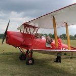
A Pair of Pups - Finished
Archimedes and 2 others reacted to MikeC for a topic
The last couple of weeks have seen setbacks like a broken strut; diversions like a HKM Meteor (also on the bench) and doing a bit of "due diligence" on a potential mask cutter purchase; and some real life stuff. So there has been slow progress, but progress nevertheless. To cut a long story short, she's now a biplane! OK, no more modelling today, that's going to need some serious setting time before rigging the flying and landing wires, adding the engine, tidying up the paintwork, weathering, and sorting out a base. Do I dare say the end is in sight?3 points -
OK, my order has been parked in Chicago for the last three days now. With any luck, I should have it in the next few days.3 points
-

Mengnut Wings Fokker Dr. 1
JayW and 2 others reacted to Wolf Buddee for a topic
More decals, more decals, and more decals, The streaked linen decals are from Aviattic. The fuselage crosses are the kit supplied decals. I’m quite impressed with the kit decals. They lay down extremely well and have minimal carrier film so two thumbs up to Meng. The cowl fasteners on the dark green metal parts that were moulded on were removed and replaced with Taurus Models Fokker Cowl Fasteners. They are two part fasteners and saying they are tiny is an understatement. However they are a big improvement over the moulded on ones as they sit proud of the kit panels and add a wonderful level of detail. There’s a lot more of them to add. Cheers, Wolf3 points -
Hi all, I finished the armor plates, primed them and applied a coat of red oxide primer. Then added some screws. For glueing the pates to the seat rails I added angles to the MDF jig that allow for a precise placement of the plates. And then the inevitably dry fitting .... Bye for now, Bernd.3 points
-
F-4C Phantom II Tamiya 1:32 I can see that the F-4 Phantom has been in fashion recently on LSP. There is no point in writing about the model because it is a model that has been available on the market for many years. I made the F-4 on an individual order. The contracting authority had two requirements. First, F-4C model cannot have the side number 829 and the second is to be an extremely worn out Phantom II2 points
-

Fokker Dr.I Mask set for MENG - 1/24
scvrobeson and one other reacted to Eagle Driver for a topic
Hey gents, this should cover the basic needs related to newest MENG kit in 24th scale. Click here for the new set2 points -
.thumb.png.84c5d3a464f2dd83f0ac37a5aac81ec8.png)
Fw190 D-9 | 1/12th scale scratch build replica
HerculesPA_2 and one other reacted to Antonio Argudo for a topic
wow, that's looking pretty cool, keep pushing that awesome cockpit, cheers (190A-8 cockpit though)2 points -

Trumpeter F-100C
scvrobeson and one other reacted to Ben Brown for a topic
As far as I can tell, the only issue with the wings is they are too thin. This, combined with the too-tall main gear tires, causes the model to sit almost level, instead of with the F-100's characteristic nose-up attitude. It's easily fixed by replacing the kit wheels with resin replacements (I found Renaissance's to just be copies of the kit wheels) and cutting ~3 mm from the tops of the struts for the 1/32 kits. Ben2 points -
So did I! Richard2 points
-
1/18 Scale Blue Box F4U-1A Corsair Modification
TAG and one other reacted to Wolf Buddee for a topic
Hi Jay, What about using a slightly smaller diameter heater hose that would infringe less on the rudder pedal’s space? Cheers, Wolf2 points -

JetMads 1/32 Viggen
Phartycr0c and one other reacted to Landrotten Highlander for a topic
The last email did say something about shipping starting 16AUG2021... Hope the heat has gone by then, otherwise I need to make room in the house for a walk-in fridge unit to work in.2 points -
Mengnut Wings Fokker Dr. 1
D.B. Andrus and one other reacted to Wolf Buddee for a topic
One thing I forgot to mention is that there is a steel cable that wraps around the firewall where the engine cowl is secured using retainers and the cable. This is moulded very fine and is hard to make out before the application of primer. There was no way I was going to be able to paint the cable so I used some silver decal stripe material from Fantasy Printshop. The decal stripes on the sheet were too wide so I covered one of the stripes on the sheet with Microscale decal film to prevent it from breaking up when dipped in water. The decal stripe was trimmed to the width I needed with (this is important) a brand new #11 blade and then applied the decal around the firewall. The retainers were painted with a small, sharp, Tamiya paint brush. This is a detail I haven’t seen on any other Fokker Dr. 1 kit. Kudos Wingnut Wings! Cheers, Wolf2 points -
So not a great deal of progress worth sharing. The little time I've had available has been spent sanding off the horrible Battle Damage Repair (BDR) patches that cover the kit's fuselage. More on that later, suffice to say, it is a thoroughly unenjoyable activity. I get that this kit is 20 years old but still, what the heck was Tamiya thinking? Anyway, a quick blurb on 589. The wonderful Fundekals profile I posted above shows her in all of her weather-beaten glory in August of '67. Just 8 months earlier, she had a much different appearance. Again taken from the Fundekals instruction PDF (Jennings, if you have any issues with me posting your work, please let me know and I'll take those pics down): Definitely a different looking aircraft. The paint is in much better shape, though it still has a few oddities - such as the OD on the fin cap used to paint out a previous squadron color and a similar patch of color used to overpaint the early serial numbers on the tail. Aside from that, she's got the early non-standard SEA paintjob with slightly unique topside patterns and the gloss white Navy undersides. Also note that these early jets had the area immediately above the horizontal stabilizers camouflaged. Later jets had this area unpainted and they also a very non-standard light grey color for the codes and "last three" of the serial number. From a hardware standpoint, the early 589 does not have any radar warning equipment fitted. As losses mounted to SAM's, the AF instituted a crash program in early/mid-'67 to outfit it's jets with RHAW equipment. This gear detected enemy SAM and AAA tracking radars and just as importantly, informed the pilot when a SAM has locked onto his aircraft. "Late" 589 has this gear fitted. A final hardware note, the early jet has the straight edged USN style inboard pylons. Later that year, these were replaced with the standard USAF curved pylons. An interesting note on these pylons - for the early portion of the war, these pylons could not mount both air to ground bombs and Sidewinders. It was either / or. Later, the AF introduced modified AIM-9 launcher rails to provide sufficient clearance to finally mount bombs and Sidewinders. Last (I promise) note on the early jet - it's not 100% certain that it had the "donkey d***" undernose fairing installed or not. In typical Fundekals manner, an alternative profile of the early jet is provided. I personally like this profile better. Anyway, that's it for now. Gotta get back to sanding and re-scribing.2 points
-
Thanks, Kais. Actually... you are correct. When I went to shim them last night, I discovered the problems you mention. One thing I want to avoid was to sand near the large screw heads inboard of both upper wings. So far, this is the only picture where I can actually see them. Nobody takes a picture of this area on any plane. But they look more flush here. Maybe I should replace them with flush screw heads made with a beading tool and a knife. Opinions??2 points
-
rudder and stabilizer riveting, scribing, priming, blank assembly [img more pics[url=https://lapatrouillesimple.forumgratuit.org/t369p25-le-franc-suisse-ou-ms-540-alias-doflug-3802]herei[/url]2 points
-

MH-6M Little Bird
Greg W and one other reacted to Pete Fleischmann for a topic
Thanks all! appreciate the kind words! Just about ready to close-up the killer-egg fuselage. A few fit issues from the aftermarket bulkhead that took some head scratching to resolve, but all good- a few projects on the bench at once! cheers P2 points -
Talk about timing... Tom Anyz put up a post 12 minutes ago for a new product he has.2 points
-
Been thinking about how to jazz up the cockpit a bit. It's not one of T's best efforts. Then I came across this picture: Hmmm.... I may have to go over to the dark side. EDIT - to my chagrin, these are actually 48th scale for the new Tamiya F-4B. That being said, Quinta is supposed to be working on 32nd F-4C cockpit bits as well. If they are anything like the ones above, they will be mind-blowing!2 points
-

HK "Nose Art" Lancaster B MkI R5868 QL/Q No. 83 Squadron
scvrobeson and one other reacted to Greif8 for a topic
I joined the fuselage this week and spent a fair amount of time cleaning up the joint seam. The seam at the rear on the inside had to be filled as this can be seen when viewing the cockpit from the rear. I did that with a combo of evergreen strip cut to size, and then a few tiny pieces of the same stuff melted into place with Tamiya quick setting glue. It was then hand painted. All that took a surprising amount of time to do and as it is pretty boring work, I did not take any photos of the progress. I also "made" the forward escape hatch. I will explain the process I used in the photos below. First up though is the buttoned up fuselage. Not much to say here, it looks the part I guess. The opposite side. View from the rear. It is out of focus, but you can just make out some of the filling I did to the seam. Also, unsurprisingly the interior is fairly dark. The maps turned out well. So the escape hatch. I thought a lot about how to replicate this. Until fairly late in it's production life, the Lancaster escape hatch was 26.5" long x 22" wide, 67cm x 56cm for us metric types! That scales out to be 2.09cm x 1.75cm. Part P13 is where the forward escape hatch was. You can see in the above photo I traced the hatch in the correct scale dimensions with a pencil and flexible ruler. I forgot to take a photo of the next step for the exterior, but I lightly scribed the outline. I'll explain why below. And here is the interior of the hatch traced in. I then cut up some wing walkway boundary decals, as well as the rounded corners of some handle outline markings and applied them over the traced area - all this is still drying. Photos I have seen show "No Step" or "Do Not Step" in red and white lettering at the front denoting where the ummm Opening Handle is. As you can clearly see in the macro photo I ended up using the German "Do Not Step" as I don't have any red lettering in English. Fortunately you can't read it at normal viewing distance given its location in the aircraft. The white lettering is a decal from a Dauntless decal sheet, and of course say's something else then what was actually said. Again, you won't be able to read the words at normal viewing distance, and you might not even be able to see much after everything is in place. I plan to replicate the exterior in similar fashion, hence the light scribing to give me reference lines to decal after painting. Macro shot of the part test fit in place. I am sure once the turret is installed much of this work will disappear. Macro photo from the front. It is pretty clear that the turret is going to cover the majority of this up, which is good as there was a bit of silvering in a couple of areas!2 points -

Tweak Lists!
kalashnikov-47 reacted to LSP_Kevin for a topic
There's been a bit of understandable confusion on the forums of late about where our Tweak ListsTM are located (well, they're mostly Thierry's tweak lists actually). They are located in the Marketplace section of the main website, but this will be subject to change and reorganisation down the track. In the meantime: Tweak Lists! Kev1 point -
The RN ground crew who applied these decals to their Merlin should be fired. Obviously they didn't Future the helo first. And honestly, would it have killed them to use a bit of Micro Sol as well? SMH....1 point
-

Make the others jealous
scvrobeson reacted to LSP_K2 for a topic
Newer tooling, not the antique.1 point -
RAF FG.1 XV571 WILD HARE Phantom Conversion
Martinnfb reacted to D.B. Andrus for a topic
Anthony Your dedication to accuracy and persistence is inspiring. Wonderful results. Cheers, Damian1 point -
I merged these two topics1 point
-
Jay, That cockpit is just awesome. I honestly thought I was looking at pics of the real thing at first.1 point
-
The Helldiver has arrived.....
Kagemusha reacted to thierry laurent for a topic
I just ordered a limited edition Mk.5 from the French distributor on eBay. It has a different spinner boss, a smooth pilot canopy and French decals for the Dien Bien Phu battle era! I ordered it as that was exactly the version I am interested in. The frustrating part is the fact I should get from Germany more or less at the same date the Navy one I intended to convert into an Aeronavale bird! So it looks I will need to ask my friends if someone is interested in a Navy Helldiver!1 point -
Mengnut Wings Fokker Dr. 1
scvrobeson reacted to Wolf Buddee for a topic
Hi Matt, I rarely build the same subject matter twice so it’s highly unlikely that I’ll get the 1/24th scale one. Unless, of course, someone graces me with a wonderful present. Christmas is coming, right? The Wingnut Wings instructions would have been a huge step up from Meng’s but I guess we’ll have to be happy with what we have. Cheers, Wolf1 point -
1/18 Scale Blue Box F4U-1A Corsair Modification
JayW reacted to brahman104 for a topic
I can certainly imagine the frustration with the hose fitment Jay.... it's always a problem with scratchbuilding and certainly the amount you're doing here, I'm amazed that you've been able to cram all that detail in and not have it happen multiple times already! Looking forward to you wheel well work; I know you won't disappoint! Craig1 point -
That looks real nice Tom, but big money there! Jeff.1 point
-

Mengnut Wings Fokker Dr. 1
Wolf Buddee reacted to scvrobeson for a topic
Excellent update! Really like the look of the decals and paint. Matt1 point -
Stunningly beautiful work Mark. I had the chance to see the actual machine as a boy and your build captures the look exactly! Ernest1 point
-

HK B-17...C 5/4 sweating the metal
Bomber Command nut reacted to Dennis7423 for a topic
Brahman, good news coming your way! Armory is going to be releasing several B-17 wheels in the four major scales (1/32, 1/48, 1/72, and 1/144), and they are including early B-17 wheels/tires in their lineup! - Dennis S. Thornton, CO USA1 point -
1 point
-
I grew up poor, in a suburb of Detroit. I made my own toys with cardboard boxes and surgical tape that my mother would bring home from the hospital where she worked. Ever hear the phrase: "If you don't have anything nice to say, say nothing at all"? Please think of it often. I'm not poor any more.1 point
-
HK "Nose Art" Lancaster B MkI R5868 QL/Q No. 83 Squadron
Alain Gadbois reacted to Wolf Buddee for a topic
Nicely done Ernest, I’m sure the crew will appreciate the irony of the escape hatch’s “Nicht Betraten” warning, LOL! Cheers, Wolf1 point -

Fw190 D-9 | 1/12th scale scratch build replica
Antonio Argudo reacted to dodgem37 for a topic
Boy, does all of this look good, or what? Are the cards' colors printed from your printer or are the cards store bought? If they are store bought, do you have a link? Thank you. Sincerely, Mark1 point -

Quinta Studio Vinyl “Decals”
Whitey reacted to Smokeyforgothispassword for a topic
Sorry if this has already been posted, but here’s a guy using them to great effect https://youtu.be/9DIkqlb4ojU1 point