Leaderboard
Popular Content
Showing content with the highest reputation on 02/03/2024 in all areas
-

1/32 Kotare conversion; Supermarine Spitfire LF Mk.Vb YO-A 401 Sqn RCAF.
KiwiZac and 16 others reacted to monthebiff for a topic
Managed some good progress on the wings during the week. First up I needed to fill the oil cooler recesses and with the excellent fit of the Kotare part I figured why bother with filler and use the kit part instead as so much easier and cleaner and with that it was chopped apart and then the lower part glued in to place requiring minimal filler I then cleaned up the lower blisters from the AML set and realised they have dropped the ball a bit in making them symmetrical which they aren't so I taped them together and sanded them down as much as possible. Before and after May need some more adjustment and it is quite subtle but on side is flatter than the other as well as the bottom of the teardrop being much rounder. A quick test fit along with the HB oil cooler which needs some remedial work regarding the shape. I've also added the Hispanno cannon shell ejector exits Then on to the upper wing, some re-scribing and test fitting th resin bulges Plenty of clean up to do but have a very clear mind where I'm going with this. Regards. Andy17 points -

Navy Phantom II aircrew by Reedoak, 1969 - late 70s : last versions with visor up
scvrobeson and 9 others reacted to norbert for a topic
Hi Further to the F-4 aircrew for the 1969-late 70s era, Reedoak provides now versions with visor up, and with or without boom mic, in 1/32 and 1/48 scale Cheers Norbert10 points -
...in Japan. 1 x 1/32 Tamiya Mistubishi A6M2b Zero Fighter - Model 21 2 x 1/32 Revell Me-109G-6 1 x 1/32 Hasegawa FW-190D $106. Shipped to Yokota. AFO parcel to the US @ $27 (he told me). It hasn't arrived yet. The bulk of the savings is with the Zero. I should have bought three! It's Christmas all over again9 points
-

1/16 scale scratch built AT-38B Talon-The Smurf jet is back!
Azgaron and 8 others reacted to Pete Fleischmann for a topic
Everything seems to get made three times- just how it goes- P9 points -
1:18 Scale B-17G Flying Fortress Forward Fuselage
BiggTim and 7 others reacted to patricksparks for a topic
A little update, I have printed some preliminary seat frames with the armor plates for the flight deck, they need a little tweeking, but pretty good.. I just happened to have a 21st century 1:18 scale pilot figure which has movable joints, which I never thought about how much it can help to get a real image of how things fit together..sizes look pretty good so far.. I had some old printed cockpit parts that were a free download for a RC B-17, instrument panel, throttles they are ok but I have aready drawn a new panel and will also draw a throttle set up to fit better and a bit more detail...I finally got the chin turret drawn and printed, pretty good but I need to tweek it a bitdiameter needs to be reduced slightly which I can do in the slicing program but I also need to open the barrel ports slightly.. enjoy, Pat8 points -
Myself I was not originally too fond of Japanese aircraft. I bought the kit because I was curious about the new technology of model-making and wanted to discover the shapes of things to come. But then I became gradually infatuated. Like they said in a famous song, ‘if you cannot be with the one you love, love the one you’re with’. @zaxos345 Thanks John! Glad you like it. Trust me Dennis. The interior is just an appetizer. The main course comes with the exterior, camouflage and weathering. The Kate is one of the airplanes who wears her backstory on her skin. The same Kate in PH will look different whether she’s in the Ceylon raid or at Midway some months later. Specialists are still battling among themselves. Hey, what would we do without temptation? A glimpse of what’s in store… Cheers, Quang8 points
-

Tamiya F-16 Aggressor, Kicked Up a Notch, April 11/24: Lighting Details
Marcel111 and 7 others reacted to chuck540z3 for a topic
February 1/24 February already? I’ve been modeling close to a month now and I’m only starting to feel comfortable with all things plastic, resin and paint again. After taking a modeling hiatus for a year, simple things like paint mix ratios, airbrush pressures and gluing techniques had left me, but it’s all coming back to me now. For instance, I know that with a certain airbrush and type of paint I need the air pressure regulator to be about “there”, without even reading what the numbers are. With a few paint splatters and quick adjustments, I figured it out in a hurry! One small item I didn’t mention earlier is the HUD, which is the earlier version for this Block 25, which is the one supplied with the kit using parts using parts N4, N5 and the clear part L1. The Aires version at the bottom is just the sides of the HUD glass with no overlap on top of the glass, which is more accurate. Further, gluing clear parts to metal can be a nightmare, especially when using CA glue, so I opted to use the kit HUD instead, by cutting off the side portions from parts N4 and N5. Here it is assembled and carefully glued with Tamiya extra thin cement instead, leaving no glue marks. More on this below. It's finally time to paint the Aires landing gear bays and cockpit, which I always start with gloss white and black respectively. I use Tamiya lacquer from a rattle can, but I’m sure the “LP” line of Tamiya lacquer paints in a bottle work just as well. When that has dried, I applied a good coat of Tamiya X-22 acrylic clear gloss. Why so much gloss black paint? · Many instrument panels are black to begin with · Black paint creates interesting shadow areas in areas hard to paint · I use a lot of cockpit decals, which need a smooth surface · Subsequent coats of enamel paint can be easily removed with solvent, if there is a protective layer of X-22 I did the same for the landing gear bays, only this time with white, with roughly the same logic as above. To keep the black areas black, I applied a mask of Mr. Masking Sol Neo, which I find works really well when you need to remove it from small tight places after it dries. Micro-Mask on the other hand, is almost impossible to remove from these same areas, so I never use it in cockpits. This next pic is sad to me, because my extensive line of Model Master enamel paints are no longer made by Testors. I use enamels in cockpits and landing gear bays, because painting flaws can easily be removed with solvent, which you can’t do with acrylics. Thankfully I still have about 70 bottles of MM paint, although I didn’t have the exact F-16 color noted below, so I used Neutral Grey (FS36270) instead, which is really close. After a little weathering, you’ll never notice the difference. After carefully removed the liquid mask, most black areas came out looking pretty good, but there are always rough looking areas where the grey paint leaked underneath. No worries, because a little solvent on a brush- with X-22 protecting the black lacquer underneath- removes these flaws easily. The Aires kit comes with 4 pieces of acetate (1 small one missing below) that are perfectly clear, so you need to paint the back of them white, or you’ll never see the gauges against a dark background. The Aires instructions, if you can call them that, don’t mention this critical step. Using a very iterative procedure of painting certain areas grey and black, then correcting overlapping flaws, the margins of the black instrument panels become sharper. The many switches and small dials were then painted using a plastic toothpick from an old microbrush. After applying many tiny labeling decals, I then sprayed everything with Tamiya Flat Clear lacquer and added a few pastels here and there to make the cockpit look used. I left a few of the smaller parts off for fear of breakage and loss, until final assembly. The joystick and HUD are only dry fit for these pics and will be installed permanently at the end of the build. That HUD might be a bit too high, so I'll likely drop it a mil or two by sanding the base before I glue it on. With the coaming removed, you can see where I added some boot wear to the floor to match what I see in Jake Melampy’s Viper Guide, that shows clear chromate green exposed along the side of the deepest wear that looks dark grey/black. As mentioned above I used lots of tiny cockpit decals, mostly from Airscale and Barracuda. The P-51D decals from Barracuda are especially good for cockpits, because there’s lots of them with tiny plain white lettering that you can’t read anyway, which work very well on a black background. The Airscale 1/32 Jet Cockpit Labels and Warnings (AS32) set will come in real handy when I paint the seat, as you will see soon enough. Placement of the decals was a hit and miss affair to make things look busy, while trying to mimic some of the pics in Jake’s book. A lot of what you see on the floor and rear wall will be hidden when the seat is installed, so I think I might leave the seat loose so that it can be removed later. Speaking of the seat, I am NOT looking forward to using those Aires (or Tamiya) metal seat-belts. How do you paint them, then insert them into sharp buckles without scraping off the paint?! So that’s it for now guys. It’s great to get passionate about modeling again, although my retirement is getting in the way of modeling again far too soon. My wife and I are going on a 6-week cruise to New Zealand, Australia and Polynesia in a bit over 2 weeks, so there will be no more modeling during that time until April. I’ll see what additional stuff I can get done to this Viper before that happens! Cheers, Chuck8 points -
CF-121 Redhawk (Trumpeter Mig 21 UM)
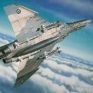
themongoose and 6 others reacted to chrish for a topic
A project designed around a WHIF based on images from an April fools joke Nothing corrected or, added to the model (except an AOA vane and decals) Painted with Alclad metalizers and Tamiya and Vallejo acrylics and a couple pounds of putty. "Ready for inspection" may be a bit of a stretch...more like calling it done. Please be gentle. I didn't get a great fit for the canopy and my clear coat made a kind of a swoop/ discolor on the port side behind the cockpit As always, striving for mediocrity Thanks for looking7 points -
Ok, time to put this thread to bed, clearly becoming political.7 points
-
Much to my surprise the exterior details of the Wasp are now completed, leaving 'only' the cockpit and AS.12 loadout to do. Having spent longer though than is probably good for one's sanity on Planet Torpedo recently, it's probably a good idea to list the symptoms below.... It started innocently enough in trying to work out the remaing surface features that festoon the helicopter beneath the cabin area: In the process of working out what went where, it occurred to me that as such prominent features, the torpedoes and their carriers make a useful datum for scale and position of the features surrounding them. Not a whole lot of technical documentation freely available on the Mk.44 torpedo that I could see, but did find a useful summary on general torpedo design procedures produced by US Naval Ordnance Systems (Hydroballistics Advisory Committee) in 1974: https://apps.dtic.mil/sti/tr/pdf/AD0777092.pdf Of greater help however for the Mk.46, in 1978 Naval Ocean Systems Centre produced a well-illustrated summary in of this Mk. in terms of its physical characteristics and visual appearance of different range Exercise, Tracking and Warshot variants: https://apps.dtic.mil/sti/tr/pdf/ADA081111.pdf Tying this documentation in with photographic references meant that at least I had some idea regarding the original function of what I was reproducing in scale form: One problem I stumbled over in my references for the carrier itself was that I had a variey of close-up photographs which, being devoid of wider context, fooled me into thinking that there were perhaps two different types of carrier for torpedoes/bombs. The PNs are explicit however that as the Wasp in its operational lifetime carried both Mk.44 & 46 torpedoes, the same EM/EF 100/1000 was used for both (with no mention of subsequent Mods): The quandary with regard to what I was seeing in photographs was finally resolved - as always - by discovering the missing piece to the puzzle; in this case an image showing a close up of the carrier ID platge which matched the one I could see faintly in the excellent shots which @Anthony in NZ had taken of the carrier on NZ3906: This clarified that there ween't two different types of carrier, only that the one carrier has a different arrangement of features on each side. The giveaway (once you understand this) in wider contextual photos is the silver cylindrical fuzing unit visible on the Stbd side and the prominent rectabgular ID plate in the centre of the Port side. makes sense in hindsight but you always doubt yourself in such situations reliant upon photography until the evidence resolves itself! Interestingly enough the Weapon Stations graph in the PNs indicates that a Mk.46 was only ever carried on the starboard side of the Wasp. Starboard view of carrier: Port: A Mk.44 to hang from it: I divided the Mk.44 into warhead/fuel-tank/afterbody/propellors(x2) and parachute bag sections for print purposes. to align all the parts during assembly a channel down the middle for brass rod helps everything align along the longitudinal axis, with a similar side channel to line the sections up laterally: Iused the same sectioning/channel methodology on the Mk.46 as well: Whilst their diameters are the same, the 46 is longer than the 44, with different propellor, parachute and guidance features, as well as differing port/surface features. At the rear, the prominent battery unit and fire control sockets are visually similar hwoever, and, as far as the RN/RNZN are concerned, the same Type-C suspension bands utilised for holding both variants in place: Assembling the torpedo(es) onto their carrier, I wanted a strong but visually unobtrusive method. The release hook of the real thing obviously wouldn't be strong enough in itself at scale to suspend either torpedo body from, I elected to use a brass pin between carrier and torpedo in a manner that should be largely invisible to the eye when the parts are glude together: Additional strength and stability will, like the real thing, come from the sway braces: A Mk.44 and carrier combined: A Mk.46 alongside a '44 to to compare visual differences: Having those features as visual landmarks on the underside then let me carry out the rather painstaking detective work involved in adding the various small fittings and fuzing units &etc. arrayed around the underside of the cabin: This step-like feature to port isn't a step I don't think as it has no counterpart to starboard. My only though it that it might be a parachute mounting for some other payload than torpedoes or bombs but have no evidence or documentation to back that up: The I-band transponder up front however has a clear purpose as part of the MATCH system between Wasp and frigate, with the pitot inboard of it: The front diagonal brace of that transponder seems to have an odd 'kink' in it in several of the photos I have: I thought initially they all just showed the same damaged one but this artefact is present on multiple airframes, leading me to wonder if this is that so that it follows the contour of the airframe when the transponder is in stowed position: Again, pure specualtion on my part. The above features with carriers fitted: - and a Mk.44 attached: Renders versions of same I need a break for a bit after that to start outputting the parts involved there prior to beginning work on the cockpit. It doesn't help that myself and wife are currently addicted to Le Bureau des légendes and bingeing through Season 1 with several more to go. Extraordinary writing and performances. Anyway, before this turns into TV Guide, I wish you all the best until next time. Tony.7 points
-

i will be singing off...............
F`s are my favs and 6 others reacted to Oldbaldguy for a topic
Sorry, I don’t follow. Are you saying that you are leaving LSP because people here build models of Russian airplanes or is there something I missed in translation?7 points -

1/32 Hasegawa P-47D-30 "Duck Butt"
scvrobeson and 5 others reacted to Tolga ULGUR for a topic
This is my recently finished 1/32 Hasegawa P-47D30 with the markings of "Duck Butt" from 9th Air Forcce, 367th FG, 329TH FS in France (Spring 1945) Additional parts are: -Aires cockpit set -Yahu instrument panel -Eduard seat belts -Quickboost engine and Trumpeter's magnetos -Barracudacast wheels Paints are Alclad metalizers and Tamiya acrylics. You can find the build story by using the following link: Happy modelling6 points -
I just don’t get the whole - “I can’t build models of x because of its horrible history in RL”. By that standard, no F-4’s because they, on occasion, may have napalmed villages in S Vietnam, no Lancasters because of Dresden, nothing Italian or Japanese (for obvious reasons), no IAF subjects cause of issues in Gaza, the list goes on forever. Every aircraft that flew in combat did bad things on occasion, that’s kinda what happens in war.6 points
-

HKM A-20J/K in progress
scvrobeson and 5 others reacted to Dennis7423 for a topic
Just saw on Facebook that this is ready for release, and this kit will include nose weights, AND metal landing gear :-) - Dennis S. Mount Juliet, TN USA6 points -
i will be singing off...............
BiggTim and 5 others reacted to thierry laurent for a topic
Hi Jack. Why cancelling your account? Simply stay out of some forums and websites for an indefinite period is also possible. And this gives you the opportunity to possibly come back here or elsewhere whenever you want...no?6 points -

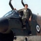
It helps to have a son in the Air Force...
lawman56 and 5 others reacted to Smokeyforgothispassword for a topic
Any chance you'll be putting your Son up for adoption? I can throw a couple of Airfix TSR2's in to sweeten the deal?6 points -
1/16 scale scratch built AT-38B Talon-The Smurf jet is back!
Uilleann and 5 others reacted to Pete Fleischmann for a topic
Hey OBG- Godzilla is my boy. I made all of my sons watch every Godzilla movie with me..the campy-er the better. They love him too. We have just about every Godzilla toy made. The one you noticed is my favorite. This one logged Many hours on the floor knocking over buildings made with foam blocks. Now he protects my bench from Rodan, marauding cats, and my general buffoonery. Occasionally he holds a model part or assembly, but I try not to distract him- P6 points -
Academy F18D Hornet 1:32 "Night Attack"
TankBuster and 4 others reacted to Mel for a topic
Hello guys, while the f15 spare parts arrive, I have started the academy f18 at 1:32, this time I will use the redfox interiors but I have also ordered the fifth sudio ones (the large set, the one that comes with the side walls, the ejector seats and other details that redfox does not have), the resin air inlets from Dmold modelworks and waiting for the double layer masking tape, what aftermarkets do you recommend to improve it further?5 points -
Hi all, I started a quick build this week. My six year old grandson asked if I could build him a plane for this desktop. Rather than just build him a model,I decided to build one on a stand (1:24 Airfix) with working prop. I picked the old Revell Corsair. It has the unique wings that he likes. All detail is filled and sanded.A lot of filler and sanding ! Leaving just the overall shape. The most difficult step was fixing the canopy and the electric motor from a small racing car. It works on a 1,5 Volt AA-battery. Next is to choose the color. I shall stear him towards a Navy-type one. But if he decides it has to be pink...!?5 points
-
Revell 2024 catalogue
LSP_Matt and 4 others reacted to thierry laurent for a topic
Hi guys, As we already knew nothing really new is announced except the Meteor. Alouette II is at last coming back and it is interesting to see the Me110C and Harrier in the catalogue as they came back not that far in the past. The old Viper dog is also coming back with new decals. To me the interesting part is actually some other sections of that catalogue. Not that far people were announcing the end of Revell as a model company. Well, to my eyes, the contents show the opposite! Revell is cleverly working to attract youngsters: dozens of models linked to various well-known movie and series franchises, drones, many cheap fun RC models, snap kits such as the recent 1/32 Me109, 3d puzzles and so on! This diversification of the concept of 'model' is actually what will preserve the company profitability and future! And it looks there are not many companies in that arena that are doing the same (Tamiya being another exception). This possibly implies few fully new classical kits will be released yearly but at least this ensures the company will keep the means to make them even if this does not sell that much. Frankly I'm impressed! Have a look!5 points -
Rather than make a grand announcement about cancelling your membership, etc, why not just walk away from the forums, relax and focus on whatever you want to focus on? If you feel like returning at a later date, come on back. We'll still be here. As a side note, I feel 100% the way you do about Russia. Take care bud....5 points
-
Work continues, the sheet metal is assembled and the interior is ready.5 points
-

Fokker Dr.I Meng 1/32
Rick Griewski and 4 others reacted to Copicops for a topic
Continuing with the fokker, I made the MGs with the photoetched cover and finished the cockpit: I tried to make a circular polished effect on the ammo case with AK true metal, not really convincing but it will be not much visible inside the cockpit. Next was the cockpit weathering, I made some dust effects due to this aircraft flew from grass airfields. Then I started assembling the engine, its really well detailed, I primed it with mr surfacer 1500 but later I airbrushed another coat of AK Xtreme metal Black base.5 points -
A little bit of good news about the Typhoon rebuild.5 points
-

Clostermann's LO-D by Airfix Spitfire Mk.IX
chaos07 and 4 others reacted to Dpgsbody55 for a topic
The wings are on now and it's really starting to look like a Spitfire. Having completed the right wing innards after my last update, the instructions have you gluing this on without the top wings being on. A bit wierd, I thought, but I found that there was method to the Airfix madness. The wings glue to the fuselage by the wing spar centre section to the engine fire wall and at the back by the wing fillet and fuselage. I taped it into place at both ends and found it needed clamping at outer end of the wing fillet. Then I noticed a gap developing at the front where the wing spar butts up against the front of the wing fillet, so two G clamps were applied. This was left to dry thoroughly before attempting any more work. The next stage is to add the top wing surfaces. When doing this, I'm always tempted to firmly clamp it all together four ways from Sunday along all edges. Dont. If you do, you'll finish up with a nasty step between the wing fillet and the upper wing surface. The plastic on the fillet is much thicker than the upper wing. Test fitting showed an almost perfect gap if the upper wing is just layed on, so to add a bit of support I added a small length of 1mm x 0.5mm stock plastic strip to the top of the rear spar. Not enough, so I added a second piece. This provides the right spacer for this joint. Glue was applied to the wing top leading edge, tip and rear spar joint only as far as the aileron and adjacent area to the aileron, and lastly along the wing fillet. Once in place, tape was used to hold it all in place, and a couple of clamps at the outer end. No clamp or tape was used near the wing fillet. Correct dihedral is also not an issue here if the lower wing is properly assembled and the joint to the fuselage is done carefully. This gives a very nice joint in what is often a problematical area. The other side was done in the same method. Once dry, the tail plane was added, but without the elevators and rudder. The joints were finished off using one application of Mr Surfacer 1200 except for the lower surface of the left tail plane which needed two applications of Mr Surfacer 500. Here it is after clean up, which is easier before rudders and elevators go on. Here it is now with the last of the tail installed and the engine and cradle test fitted into place, mostly for inspiration. The engineer's one foot ruler gives an idea of the length of this model. The engine was quickly slapped together after the three individual assembles were painted as shown earlier in this build. I have two small problems to attend to now. The first is with the upper wing surface, around the outer edge of the cannon bay. The plastic here is buckled, but I think if I can get the paint off the two surfaces, I can glue this together without creating other problems. The next is also with the right wing upper surface, as the trailing edge in the middle of the flap recess is wavy. Perhaps a little steel wire clamped and CA glued to this may fix it before I add the flap itself. That's it for now. Once I get these two problems sorted, it's on with the radiators. Cheers, Michael5 points -
1/16 scale scratch built AT-38B Talon-The Smurf jet is back!
Shoggz and 4 others reacted to Pete Fleischmann for a topic
argh!!!!5 points -

Desktop Corsair : FINISHED
Landrotten Highlander and 4 others reacted to themongoose for a topic
South American markings maybe?5 points -
1/16 scale scratch built AT-38B Talon-The Smurf jet is back!
Christoffer Lindelav and 4 others reacted to Oldbaldguy for a topic
Several photos up in the thread I spied a sub-scale Godzilla among the many things on your bench, Pete, and was wondering if he was photo bombing or if he has a job. My smaller version of the same critter has guarded things I consider important for almost 60 years. I found him discarded on the ground decades ago and, after a good scrubbing, have had him ever since. He lived in my field box among my horde of Eberhard Faber Ebony pencils, kneaded erasers and cheap water colors while I was in college before moving up to my big hangar tool box years later to protect seven different airplanes and an equal number of BMWs. He looks much the same now as he did then - that Gatorade-looking yellow green that looks like it might glow in the dark - and still does a manly job of keeping order on my bench to the point that I can’t imagine life without him. My son understood the importance of the thing but not the special bond that has developed over the years and tried to purloin him for the same mission before heading off to his first assignment. I sensed that something was afoot and rescued the little bugger at the last minute. Always on the job, never misses a thing and is good company. Highly recommended. Everyone should have one.5 points -
Well, back to work. After a "dream" week at my in-laws' (but what possessed me to go there with my wife???) I'm back at work. I'm making slow progress because my weak point is assembling and gluing the plastic parts. I always use too much glue and I'm still having a bit of trouble getting to grips with Tamiya extra-thin glue. You can sense her willingness to go to places where she's not welcome. In the company of a very famous Belgian, I assembled the fuselage, which isn't as easy as all that: ICM's fuselage cut-out makes it not very rigid. At the front there's only a small contact point in front of the cockpit, and at the rear it's a bit better from the top of the fuselage to the rudder. Underneath there's nothing. The following photos show an upper panel glued in front of the cockpit, and underneath a more or less triangular panel simulating the canvas. The good thing is that there's virtually no conventional glue line, so less sanding and trimming. I also worked on the wings, in particular the U/C housings, with the installation of lots of useless Eduard kit stuff. I added hoses for the U/C hydraulic fluid. I also made the rivets on the U/C doors. The plastic is really nice to work with, but the most remarkable thing is the overall finesse of the engraving of the structural lines of this aircraft. It's great art, and the overall effect is truly superb. One small negative point: I'd have liked the engraving of these structural lines to have been deeper, as they're too easily erased at the slightest sanding. Denis, who gained 2kg in a week. Thanks to the Riesling and choucroute... C'est la vie !5 points
-

Building the Border 1/35 Kate. Got paint!
The Madhatter and 4 others reacted to quang for a topic
INTERIOR DONE! The 3-crew stations are detailed and painted although I’m well aware that much of them will NOT be visible through the narrow openings. As I don’t know yet what would be visible and what would’t, I gave it the whole treatment. At least I can sleep with both my eyes closed. Without much ado, here are the pics… The main assemblies Stock IP painted with kit individual decals and glazed bezels Side panel arrangement Spare m.g. clips. Note the trailing antenna spool below them. Stored Goertz type10 bomb sight I made the oxygen bottles for the crew from scratch… … and painted them black as per the IJN regulations. Pilot’s station. Seat belts from included PE. Shoulder belt added from tin sheet. Note the 3 red bomb and torpedo release switches on the left. Observer and gunner stations Gunner/ radioman station. Note scratch-built morse code transmitter at his right (with wood base). Interior installed. A side profile showing all the elements in place should be helpful to every Kate builder Left fuselage panel added Fuselage closed. I was a bit apprehensive concerning the fit but my fears were unfounded. Every joint followed the natural lay-out of the original panels and is invisible if the assembly is done right. Also as predicted, not much of the interior is visible through the narrow openings… Bottom view of the assembly. Note how the parts fit together. That’s all folks. As always, comments and questions are welcome. Thank you all for looking. Cheers, Quang5 points -
1/32 Kotare conversion; Supermarine Spitfire LF Mk.Vb YO-A 401 Sqn RCAF.
Anthony in NZ and 4 others reacted to monthebiff for a topic
I decided to spend some more time sanding the deleted gun covers on the upper wings as Kotare have these sitting slightly proud on the kits which gives some nice visual interest but definitely not needed on the B wings smoothed out as best as I can. and under a light coat of primer very happy with how that has gone and now to the lower wing Initial sanding complete and then under some primer Pretty happy so far but will let everything cure and shrink back should it wish to before a final round of filling/sanding....how very painful. Regards. Andy5 points -

i will be singing off...............
scvrobeson and 3 others reacted to blackbetty for a topic
i still dont get your reason for leaving, Jack4 points -
Right, one does have to establish sensible priorities.4 points
-
Another short update, par for the course lately it seems. The only things I have shot photos of is the progress with the anchors; the rest of my recent work has either been cleaning up parts, though that is about finished as there are not that many more parts left - rigging will soon be the only focus for the build. Researching how the studding sail booms and yards were attached and worked brought to light some interesting information. I will describe those items in a bit of detail here as some of you may find the information interesting and useful. Like most warships of the time the Consititution was capable of utilizing additional sails in light wind conditions. Known as Studdingsails or "Stunsails" for short, they were attached at the end of the yards to increase the amount of sail area to catch light wind in order to gain at least a small increase in speed. On the Consitiution only the Fore Yard, Fore Topsail Yard, Fore Topgallant Yard, Main Yard, Main Topsail Yard and Main Topgallant yard were equipped with the booms and yards required to attach and work the studding sails. Further, only the booms for the Fore Yard, Fore Topsail Yard, Main Yard and Main Topsail Yard had the booms attached. In addition, there was a Fore Swinging Studdingsail Boom that attached to, and was worked from the channels for the foremast located on the hull sides. The kit provides a Main Swinging Studdingsail Boom, but historians agree that the ship never had those. The kit gets the setup wrong; not surprising as it was designed in the late 1950's and went into production in the early 60's when it was thought that the way the Constitution's Studdingsails were organized on the actual ship at the time the kit was designed and the molds made was correct. Research in the 1980's corrected that mistaken impression, but the molds were never updated; understandable given the cost to to so. So what does all this mean for my build? To start, the only yards that will have studdingsail booms are the four listed above. None of the studdingsail yards will be displayed, as those were struck below when the studdingsails were. I will have to work on the yards that will not have booms to fill the small notches that are on them to place the "incorrect" booms. That would have been easier before I painted them, but I will deal with it. I have also decided to replace most of the kit booms as many of them are warped, badly molded making getting them round nearly impossible or both. I have both the material, tools and a plan to make the booms - I just need to get my skill up to speed to make them, so that I can turn out acceptable parts (I see I large "FAIL!" pile in my future.). Now on to the part of the post that most of you are actually interested in! One of the combination A/M and scratchbuilt anchors waiting for detail painting. The completed anchors. I stained the wooden stocks with a light oak stain to both bring out the wood pattern and give the color some warmth. Close up of the installed starboard anchor. You can easily make out the lashing I did to attach the main anchor cable to the anchor ring; just as it was done in real life. Slightly wider view of the same anchor to show how it was secured. Close up of the port anchor. Here is the lower part of the gammoning for the bowsprit. This was a challenge to thread and run keeping the wraps tight and aligned. Hope you all enjoyed that! Ernest4 points
-

1:32nd scale Macchi M.5
Paulpk and 3 others reacted to sandbagger for a topic
Hi all The model is now mounted onto its display base. Just the figure and propeller to complete this build Mike4 points -
1/16 scale scratch built AT-38B Talon-The Smurf jet is back!
Azgaron and 3 others reacted to Pete Fleischmann for a topic
Popped this circular panel out in brass just because I thought it looked cool-4 points -
1/32 Tamiya P-51D-5 "Little Eva III"
Starfighter Jock and 3 others reacted to zaxos345 for a topic
Good morning gents, I finished weathering the ''lady'', put on her shoes, the external tanks, wrapped up all the details and bits and i am presenting her to you!! Hope you like it!! I really loved my journey with her!!! More here... Thanks a lot, really appreciate any comment!! John4 points -
CF-121 Redhawk (Trumpeter Mig 21 UM)
Loach Driver and 2 others reacted to Out2gtcha for a topic
Great! I've really only done 1 what-if, but I have to say it was quite liberating. Well done!3 points -
I got in several hours of work on the build today and it was dedicated to making the studdingsail booms and the fixtures to attach them to their respective yards. The first step was turning birch dowels down to the correct diameters. Surprisingly I only had one redo - I was expecting to have to do the work several times to come up with the six booms required; the moon and stars must have aligned today. I then made the fixtures to attach the booms to the yards. On the actual ship these are iron hoops that are fixed to the yard, some of which can be opened. In the photos below I will describe what I came up with to somewhat replicate that. One of the birch wood booms that I made. It and the others are much better then the kit parts and I am glad I took the time to make them. Another "compare and contrast" photo. I twisted copper wire into the right sized loops and then cut a section of brass tube that was the right size to the correct length to gain the right stand off from the yard. It is a very simplified version that replicates how the real booms were attached in a very basic form. I drilled the correct sized holes in the yard to insert the end of the twisted copper. This will give strength to the bond and I can make slight adjustments if and as needed. This test fit shows I need to drill the inboard hole a bit deeper. Construction is finished. I am going to stain the booms rather then paint them. Somewhat risky as I am sure I will not match the shade of the other spars, but different shades were common on the tall ships of that time as spars, yards and sections of mast were replaced as needed, so the wood would have looked different in some areas. I terrible photo of the stained booms. After the stain had dried I brushed a thinned coat of Tamiya Transparent Yellow on the wood areas to give it a very slight sheen and add some warmth. The copper and brass were painted black to simulate painted iron. Another underwhelming photo showing the Foreyard with its studdingsail booms in place. Close up of the end of the yard showing how the boom is placed and attached. I am happy with how this, and the other yard/boom combos, turned out. I only had to make a couple of slight adjustments to get the correct angle and offset. The next phase will be adding the footrope and blocks to the yards. There are very few parts left to attach to the kit so rigging will now begin taking up most of the bench time.3 points
-
Westland Wasp HAS 1: 1/24th Scale.
Anthony in NZ and 2 others reacted to Derek B for a topic
Hi Tony, I love coming to school, er, I mean reading your posts, as they are so educational! I ran out of superlatives a long time ago, so all I can say is that it is awesome work on a scale that I have never seen before...well done Tony. Regards Derek3 points -

Hawker Typhoons in 1/32 scale?
Rick Griewski and 2 others reacted to mozart for a topic
Ok, resistance is futile! Once my 56 Squadron Hurricane is finished (today with luck) I’m starting my MDC Typhoon, and the Revell Hurricane as flown by 175 Squadron, Hurribombers.3 points -
More stuff into my place! For comparison, the TV is 65 inch!3 points
-
Hi Matt, Originally, yellow, then NATO dark green later (you will notice that there is a standard green set of front red steps). As a manufacturer, we (BAe) had red steps (McDonnell Douglas used both yellow and red steps, but mostly yellow). I think that some of the RAF units that conducted major overhaul of the aircraft (and training units) occasionally used red steps as well (but these were mostly yellow as well in the main), but at operational squadron level, they were generally gloss yellow (late 60's to late 70's, then dark green thereafter. Looks like the RN FAA preferred red steps. The above image is also BAe at RAF Scampton as per my images. HTH Derek3 points
-
Hello Jack, I know how you feel. Sometimes you just need a snooze and come back when skies are clearer. Nothing lasts forever.3 points
-

Interest in sharing of aircraft pictures from museum visits
Out2gtcha and 2 others reacted to drsquid142 for a topic
I think I can do both. Share some highlights from my museum visits as photos in a forum thread, link to my entire albums which can often contain 100's of pictures, and also curate a selection of walkaround images for specific aircraft we can add to the walkarounds section. For example, just quickly looking over the initial images I am going through now from the WW2/Cold War hangar of the RAF Museum, I have enough pictures of their Spitfire F.24, Typhoon, Tempest, Phantom FGR.2, EE Lightning, Vulcan, etc. for walkaround sets. It's unfortunate though that for many of them I didn't have access to take any cockpit photos for many of the planes.3 points -

i will be singing off...............
Michael931080 and 2 others reacted to JeepsGunsTanks for a topic
I think I get it; I don't build Nazi German equipment because after I got over my wehraboo stage and actually read up on them, I struggled to find anything admirable about the WWII Germans (except the few resistors). I just don't enjoy building them. I don't care what other guys build, at all, as long as they enjoy it. As for the current Euro conflict, all I want out of it is for it not to kick off WWIII. Neither side is clean. It's all a tiresome waste of lives and treasure. Good luck in your future endevors!3 points -
1/16 scale scratch built AT-38B Talon-The Smurf jet is back!
Shoggz and 2 others reacted to Oldbaldguy for a topic
Holy crap, Rodan!!! We need an LSP Rodan!3 points -

i will be singing off...............
Martinnfb and 2 others reacted to Rick Griewski for a topic
Must be other reasons about model building that could help you carry on. I have contempt for Russia also. I have dumped/destroyed all my modern kits, Space race models and tanks. Maybe you can build a few Ukrainian subject models, buy from ICM. I do not know if I helped or not. Take care3 points -
Awesome ladder Anthony (much kudos to TonkaXV for producing such a fantastic set of ladders). Looks like you are making some real progress on this Anthony, even if the hot end is causing you some pain. My Phantom days with British Aerospace (BAe) back in the late 80's/early 90's: Derek3 points
-
1/16 scale scratch built AT-38B Talon-The Smurf jet is back!
Azgaron and 2 others reacted to Pete Fleischmann for a topic
Top panel was done with JB Weld- Mask the panel off with tape equal to the thickness of the metal sheet that will butt-up against this panel- sand back to the tape- here you can see how the metal will butt the top panel add fasteners- here’s a look at the fuel overflow vent-3 points