Leaderboard
Popular Content
Showing content with the highest reputation on 04/03/2024 in all areas
-
1/16 scale scratch built AT-38B Talon-The Smurf jet is back!
williamj and 11 others reacted to Pete Fleischmann for a topic
Chopped out the channels for the speedbrake arms.. The gear wells have suffered some shop rash over the 14 years of construction and need some love. the printed speedbrakes from Timmy! Literally drop into place. genius. fabulous. P12 points -
Let's get up to date! There have been some issues, at least in my head, that needed to be resolved. One, the side windows. I don't like the ones I did myself. So I await the 3D printed transparencies from Shapeways - due in a week or so. It is my hope they turn out as nice as the Malcolm hood has. Two, blue paint that has been sitting for months - I feel I need to finish up the blue painting while the paint is still healthy. Because if it dries up, I will have great difficulty matching up a new batch. In the mean time, I have been working on the RH side of the cockpit wall where we find the radio gadgetry and some electrical equipment. Recall in previous posts that radio equipment for US ETO fighters was pretty simple especially for Mustangs with fuselage tanks, where the tank has used up alot of space where radio equipment went. Hence all they really had was the VHF SCR-522 equipment. Missing was IFF (identification friend or foe) equipment and low frequency radio equipment (the Detrola). The VHF SCR-522 consists of the following components: Transmitter-receiver - the big box behind the pilot's armor plate on the upper radio rack (to be done later) Dynamotor - a slightly smaller box also behind the pilot's armor plate on the upper radio rack (to be done later) Jack box - a version of this is included in the cockpit RH side stuff Radio control box - this item is included in the cockpit RH side Antenna mast - the familiar nasty looking spike antenna we see on all ETO fighters. Although this will be replaced by a whip antenna as part of the Malcolm hood modification. Here is the finished radio and electrical equipment on the cockpit RH sidewall: You see there in the forward-most bay the dominant black main switch box, below it the interior green radio junction box, and just aft of the radio junction box the fabric covered connector panel. The next bay aft has the SCR-522 radio control box with the red buttons, below it the jack box bracket, and below the jack box bracket the detonator box, and aft of the detonator box the silver mic adaptor box. I attempted to wire this equipment but the drawings are not very good - hope I got it close.... I may or may not include microphone cords. All this stuff except the fabric covered connector panel, and the red buttons, are 3D printed from my Rhino models, as usual for this build. You also see radio support brackets (3D printed), at least the one with a blank area where other radio equipment would go (IFF stuff), but is missing on this aircraft. Lastly another shout-out to Peter for the decals. They are marvelous. At this point, the sides of the cockpit area are pretty much complete. Here they are: Late additions are the flare gun stowage bag on the LH side (with the two brass buttons), and the map case on the RH side. The map case is just simple plastic sheet parts. I must mention - for those of you who followed the Corsair build, you may agree when I say the P-51 cockpit is much more simple than the Corsair cockpit. Mind you, I still have the floor to do, and some other stuff hanging off the IP panel, as well as the pilot's seat and armor plate. But there just is not nearly the amount of complexity. The Corsair cockpit was a nightmare! All right - I have been nervous about the blue paint. So what I have decided to do is to go ahead and paint the remainder of it on the windshield surround part - this: In order to do that, the rest of the skinning has to be done. And in order to do that, I have to fit this part to the already completed engine cowl, and tidy up the panel line between them. In order to do that, I feel I have to tool these parts up to one another. So I designed and built another jig: This new jig is part of a simpler plan than the one I laid out a couple posts ago. This way, I can still utilize the main jig (minus the firewall bulkhead). Construction and concept are similar to the main fuselage jig. That new bulkhead has a post on it that fits into the prop shaft hole in the nose of the engine cowl. Which will assure a proper orientation of the engine cowl to the forward fuselage both up/down, and sideways. The bulkhead can slide fore and aft in the center slot (the mounting holes are slotted), similar to the two end bulkheads on the main jig. This jig, or better an auxiliary jig, will bolt onto the existing fuselage jig that is working so well for me. Like so: Note that the firewall bulkhead has been removed. In its place is to be the actual firewall (actually a simplified version of it just for this exercise): Two parts - a top and a bottom - 3D printed. They fit onto or into the aft face of the engine cowl, which has just awakened from a months long winter hibernation. Note the firewall has the same four longeron posts that the jig bulkhead has. The beauty of digital design - the locations are identical to the zillionth of an inch. Much fiddling was required to get the firewall parts to fit perfectly into the big engine cowl part. Dimensional accuracy on 3D print parts is not quite perfect - parts grow just a bit, such that male and female parts when designed without any gaps often clash a bit with one another. That was the case here. Before using this new aux jig, I reloaded the fuselage side panels and windshield surround into the main jig, minus the firewall bulkhead, like so: The holes in the longerons are loud and proud in that picture - waiting to mate up with that new firewall. And here is the new aux jig in action with the engine cowl plus firewall loaded: f The jig is now about 13.5 inches long, and it is unwieldy to jockey around. Big model. The concept works great, but I got a bit of a surprise - tapering gaps at the firewall interface: Both sides. Not bad, but it makes me wonder if something is in error. I do notice that once the aux jig is clamped up and bolted to the main jig, despite my efforts to get it just right, its forward end has risen up a few hundredths of an inch above the flat desktop. That would cause that tapered gap, and maybe that's all there is to it. So I am going to shim between the jig surfaces to eliminate the condition, and hope that tapered gap disappears. Actually it matters little - when I skin the fuselage side panels, that gap will be hidden, and turn into a normal panel line. Still, I want that Mustang nose to be spot on relative to the rest of the model. Next steps - I believe I am going to adorn the windshield surround assembly with the electrical equipment that hangs off it - several boxes and a lamp. I don't want to do that work after I paint on the blue, because there will be alot of handling and that paint is a bit fragile. After that - then I will put the parts back into the jigs and skin the windshield surround, and then paint! You will see the results next up. Hope you like that aux jig - I sure do. Later folks.10 points
-
my latest built :9 points
-

RAF Harrier GR.3 - Norway - Matchbox 1/72
TankBuster and 8 others reacted to Piero for a topic
Hello, every now and then I get an attack of dreams from when I was a child... and then I neeed to build a Matchbox kit. This is my RAF Harrier GR.3 in the 1980s during NATO exercises in Norway. A few small details have been added, but basically the kit is from the box. Decals are from an old SuperScale sheet. Next, already in progress, will be an Hawk trainer. CIAO! Piero9 points -
Fin cap light, sanded to shape. Here are the horizontal tailplanes. Sc has come up with an ingenious design. There are 3 pins that hold both sides together and the whole thing pivots as well. And here I have joined the 2 rear sections together. Putty will be sanded smooth when dry. Dan8 points
-

Dewoitine D.500 [1:32 Dora Wings]
R Palimaka and 6 others reacted to Alex for a topic
This is a placeholder for now - I've got other things to finish first, but since the GB runs through December I should have plenty of time. I've had this kit of an attractive silvery French aeroplane in the stash for a while, so it's time it got built.7 points -

Malvinas Dagger
themongoose and 6 others reacted to blackbetty for a topic
another round of sanding and priming, still lots of little blemishes7 points -
Hello, to celebrate the 50th Anniversary of the F-16 Fighting Falcon, I decided to build a rather particular F-16, which was probably one of the few if not the only case of “unsuccess” of this phenomenal and innovative multi-role aircraft. In the second half of the 80s the USAF was looking for a replacement for the A-10 and so they thought of using a version of the F-16 equipped with ground attack devices, such as a FLIR, a laser tracker and a big cannon in an external pod derived from that of the A-10. Another aspect that certainly makes the subject unique is the camouflage, the Europe 1 or so called "Charcoal Lizard", also derived from the A-10. For the test phase, 7 F-16C Block-25 and a B two-seater were chosen. Before these there were some other tests with a couple of F-16As if I remember correctly. The test did not go well, in particular the cannon hanging from the ventral pylon when it fired caused various problems, both structural to the airframe and to the avionics of the jet, in addition to the fact that the strong vibrations made it decidedly miss the target: anyway, USAF is still waiting for a replacement for the A-10 (...). So, F-16 elegant shape + Europe 1 camouflage + external heavy weapon load has made this jet just spectacular and irresistible for me For this project, I'm going to use the Tamiya 1/32 F-16C "Thunderbird" kit. This kit contains the parts to make a Block-32 and with a few small adjustments it can be converted into a Block-25. I decided to use few aftermarket for this because the kit parts are really good just adding some details. The cockpit received instruments and consoles from Quinta Studio 3D set. Other than this, all the other parts are from the kit, including the ACES II ejection seat. Some electrical cables has been added on the back of the tube area. The undercarriage wheel bays are from the kit after, to my unpleasant surprise, I discovered that the resin parts of the Aires set are definitely too short to fit the plastic parts of the fuselage. Cables and pipes were added with some other small details. Since I had decided from the beginning that I would put a FOD cover in the main air intake, I saved myself from having build and fit the air intake duct: the FOD cover has a yellow head of a falcon drawn in the center. At that time these Block-25 F-16C didn't have the bulges above and below the wing roots and the "beer cans" RWR at the slats. These parts has to be removed from the plastic parts. Same for the 2 extra chaff&flare box dispensers under the left side. CIAO! Piero6 points
-

Zoukei Mura Fw-190 A-4
Johnny Cloud and 5 others reacted to Artful69 for a topic
Finally the standard release boxing of the Zoukei-Mura Fw190A-4 is up for preorder … https://www.zoukeimura.co.jp/en/ Rog6 points -

*** Finished*** 1/32 Trumpeter P-47D-22 "Kansas Tornado"
LSP_K2 and 5 others reacted to Tolga ULGUR for a topic
Btw, Cowling is ready for the decals6 points -

Hasegawa FW-190D "Late Version"
Azgaron and 5 others reacted to Rampenfest for a topic
Finally laying some color down! Using the Vallejo Air RLM 75, 81, and 83. The Eagle Cals description mentions that the very inner wing roots are RLM 81, so I have replicated that here. Also, some sources indicate that the engine cowling was a replacement and thus did not match the RLM 83 green in continuity along the cowl. I decided to do this as well to add some visual interest to the model. Some artistic liberty. Also got the drop tank painted up and ready for some light chipping. That’s all for now, cheers!6 points -

Hawker Hurricane K5083: the prototype
scvrobeson and 4 others reacted to mozart for a topic
Thanks Rich, so glad you're as fascinated by Hawker as me, but don't run too fast youngster cos the old man won't be able to keep up with you! All sorts of fun and games today (apart from the early morning power cut which meant my usual three cups of coffee had to be postponed, don't we take flicking a switch for granted?). Firstly the sproo-goo cleaned up well: and the surface is now smooth enough to be foiled later. So looking at the two scaled Bentley drawings started me thinking of options for putting in the new panel lines, and indeed if that is absolutely necessary? My initial intention was to cut up these drawings and use the individual panels as templates, that led on to why not draw them on the computer using the Silhouette software, cut them from Oramask then use the "masks" as templates....self adhesive so no real risk with slippage etc. So I did this for the starboard side: Advantages of doing this exercise: correct position of Dzus (or whatever they are) fasteners and the exhaust stub locations. This latter aspect will be very useful when it comes to making plastic inserts for the present gaps. Bit of an anomaly with the Bentley drawing vs the side photograph: I need to check my reference pictures closely for timings; so many features changed after the early test flights. For example the test pilot, Flt Lt "George" Bulman grumbled good-naturedly about the lightness of the sliding canopy; whilst accepting the enclosed cockpits had come to stay, he said that it creaked and flexed continually during flight, so Sidney Camm agreed to the inclusion of two stiffeners rather than one. The drawing above shows the Hurricane just before Acceptance Trials at Martlesham but Bentley's plan and port side drawings of K5083 as first flown also include the panels in question. The second option is not to do the panels lines at all but to cut the Bare Metal foil directly to shape and apply to the plastic, thereby forming its own panel lines. I did this reasonably successfully with my first Fury, which was also my first attempt at foiling: so I might do this again. Sorry to be a bit of a windbag.....kind of get carried away at times!! PS Panel issue solved; there were metal panels in those positions both port and starboard but painted silver rather than polished. Win - win!5 points -
Malvinas Dagger
Isar 30/07 and 4 others reacted to blackbetty for a topic
while things dried with the umpteenth coat of putty/surfacer/primer i drew the decals5 points -

Brush painted Kotare Mk.Ia - Weathering the underside
Alain Gadbois and 4 others reacted to Kelly for a topic
Hello there, I made a start at weathering the underside. This particular aircraft apparently has no stencils or markings on any underside surface due to its factory colours being over-painted in the field. It certainly makes for a large area to try to make make interesting! I considered putting them on anyway because I like the look of them, but historical accuracy won the day The oil streaks are extensive, but many (most?) contemporary pictures of Merlin powered aircraft seem to be almost black with oil. I'm not sure what colour to paint it, so started with a greenish-grey. Is the used oil black? The black n' white photos sure make it look so, but then they often make red look black, so I'm at a bit of a loss. Any suggestions would be super welcome. I've also found it difficult to locate exactly where the oil is leaking from. It seems to be coming from any/all panels anywhere near the engine! Modern spitfires at airshows show similar oil streaking patterns to the originals, but it is a very light/transparent colour. I'm assuming a wartime crate being flown sortie after sortie would get significant build-up, but I'm really just speculating. Painting the gun powder marks is tricky with a brush on such light colours. It looks almost airbrushed on the darker upper surfaces, but the sky colour is way less forgiving. I've done a little bit of chipping around the starboard wheel well. Silver just doesn't show up over sky, or look convincing so mixed a bit of black with it. Its a fine line though, if it gets too dark/contrasting it looks like steel or iron. I went with an artistic compromise. Really enjoying this build. Wonderful kit that looks every bit a spitfire. Can't wait for the mk.vb to come out. The V is my favourite, closely followed by the high-backed Griffon version which I'm sure we'll see one day... Sigh. Thanks for looking, and for any future insights into the oil streaking issues! Kels.5 points -
1/16 scale scratch built AT-38B Talon-The Smurf jet is back!
Derek B and 4 others reacted to Pete Fleischmann for a topic
Made it to the main gear well with the aluminum will work the sheeting around the speed brakes area, then flip it over and start on the top/sides moving back to front. Cant yet go all the way with the aluminum to the fuselage split( behind the cockpit)..I’ll need to blend the joint between sections before I can cover that area.5 points -
I may have told this anecdote before, if so please forgive me but in this context it’s worth repeating (I think ). It concerns this gentleman: Grp Capt David Bonham Carter was the Station Commander of RAF Waddington during the later years of WW2. He had previously been an accomplished test pilot but by this stage he was somewhat out of condition, rather deaf (his nickname was TR9, an early type of radio equipment, on account of the large hearing aid that he wore) and so irascible that he disregarded any notion of being in a landing circuit….he just landed! Anyway, post-war he had his “own” Hornet and he was paying a good will visit to a US base in the Far East (I’ll day Singapore but who knows?). As he approached the base an honour guard of four Sabres were sent up to escort the esteemed British visitor into land. Seeing them, BC opened his throttle, feathered one engine and zoomed past the astonished Sabre pilots. Their astonishment increased when, safely on the ground, BC reached into his cockpit for his walking stick and stomped off to the Mess. All totally true I’m assured.4 points
-
1/32 Eduard (Hasegawa) P-40N Warhawk "Klawin Kitten"
Azgaron and 3 others reacted to Tolga ULGUR for a topic
Some progress4 points -

Hasegawa P-40N
R Palimaka and 3 others reacted to LSP_K2 for a topic
This actually looks pretty cool in person, but the photos I took don't really capture it well. Regardless, I'm calling it finished.4 points -
Thank you all for your interest and comments, I’ll have a Doom Bar please Iain! After 24 hours drying time I did a bit of paring away of the goo yesterday evening and a light sanding, I think it’s going to be ok. I hope to have a good modelling session today….after 3 solid days on the garden and yesterday on the golf course (in the rain of course!) I think I deserve it. So, more soon pals!4 points
-
Ki-61-I Hien “飛燕” in the Papua New Guinea (Hasegawa 1/32)
Pfuf and 2 others reacted to sillymodeler for a topic
Hello everyone. This is my last finished 1/32 Hasegawa, Ki-61-I “飛燕 (Hien)” I chose this model as I still wanted to explore metal cladding. Hien is a suitable aircraft for this purpose because it was shipped from the factory in bare metal and then various camouflages were applied by units. I used the usual kitchen aluminum foil and water-soluble glue for the metal cladding. The hand-painted random camouflage applied to Hien is another attractive point for modelers. So, I hand-painted a crooked camouflage pattern on the fuselage and wings with an airbrush like a mechanic of the time. It was the most enjoyable thing in this build. One of the advantages of metal cladding is that you can redo the camouflage paint as many times as you like. Unlike other Japanese airplanes, Hien was equipped with a liquid-cooled DB601 engine produced under license. However, it suffered from low reliability and low mission-capable rates due to insufficient craft quality and frontline supply, and the inexperience of mechanics on liquid-cooled engines. However, as long as it was up and running, it performed as well or better than its elder brother Bf109E. I adopted a paint scheme inspired by the 68th squadron that fought in Papua New Guinea. The squadron was one of the first to receive the newly developed Hien. Papua New Guinea was far from its homeland and probably one of the harshest battlefields in WW2. Many died not only from battle but also from starvation and disease as supply lines were destroyed. It is said during the war: “Java is paradise, Burma is hell, and you can't return home from New Guinea even if you die”. Actually, most of the members of the 68th squadron, as well as many other soldiers, are still lying there. It’s basically OOB build. I just used metal gum barrels and pitot tube. The squadron marking is a combination of hand-painting and some extra decals. I also slightly modified Hasegawa’s lovely kit figure to one that resembles tropical pilot uniforms. (One more thing, I would like you to assume that my model is a reproduction of an aircraft whose tailwheel was lost in an accident on the battlefield. The tailwheel is still lying somewhere in my room.) I hope you all enjoy the model. Sorry for my plastic cup as usual!3 points -
Well, the pesky part hasn't reappeared, but I'm cracking on anyway - if it does turn up - great - if not, I'll have to scratch build a replacement - I'll think of something! Anyway, all the invasion stripes are now done. And I've started to peel off the layers of masking! Now to weather, finesse and hang all the fiddly bits - including the missing one!3 points
-
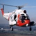
De Havilland
MikeC and 2 others reacted to Archimedes for a topic
And together with today’s De Havilland image we are asking why there isn’t a readily available injection molded kit of this beauty on the market yet? Downright drop-dead gorgeous and fast as the proverbial sh!t off a hot spade who would not like this? Kind regards, Paul3 points -
Oh man I’m so loving seeing this come together!3 points
-

Tamiya 1/32 F-16C CAS Viper - 50th Fighting Falcon Anniversary
Daniel Leduc and 2 others reacted to Zola25 for a topic
Gotta love the Lizards - I will follow this build for sure3 points -

Brush painted Kotare Mk.Ia - Weathering the underside
geedubelyer and 2 others reacted to MikeMaben for a topic
Hey Kelly, I use paint brushes, colored pencils and pastels for oil and cordite (gun) stains.. I use pastels with small brushes for gun stains and brushes and cotton buds for exhaust stains, varying in color shades and intensity. Varying colors looks more realistic to me than just black or brown. Have fun.3 points -
Hi all Here my last built: a Trumpeter Skyrader built as a n AD-4 from GC 1/21 in Algeria in 1960 - 1961 Hope you lie it!2 points
-
De Havilland
Archimedes and one other reacted to thierry laurent for a topic
Funny! I thought the same!2 points -

1/32 JetMADS Draken reservations are open
scvrobeson and one other reacted to Gary Needham for a topic
UPDATE RECEIVED TODAY from JETMADS. Hello, We are pelased to inform you that the project is progressing steadily. Our mold makers have started working, molds are beginning to come out ready for production, which is planned to start by the third week of April whereas the test printing of the 3D parts are also estimated to be completed in parallel. All pre-production works are expected to be completed around the end of April and the plan is to start full scale production by early May. All projects have their own specifics and it is generally better to make an estimate as to when shipments can begin only after the production of a kit is at full throttle, however now based on the experience of previous releases we can roughly expect the shipments of the Draken to start by late June / early July. Best, JETMADS Team2 points -
In the winter of the44/45, at the Zhijiang airstrip. the 27th Squadron of the 5th FG. The P-40N in the foreground is LIL' BUCK of Major Irving A 'Buck' Erickson. From January to April 1945, he served as the captain of the 27th Squadron, with 2.5 air to air combat kills. However , he also destroyed 21 enemy trucks in February 1945! The 27th Squadron was the last fully equipped P-40 unit in China, flying until June 1945.2 points
-
I think it's safe to move this one to General Discussion now! Kev2 points
-
I'm grown very weary of beating this bomb into submission, but I now believe all the seams are good (thank goodness). Now it'll get the OD 41, decals, and weathering.2 points
-
Indeed it would. Even a vac kit at that size would have a bit of sticker shock about it! Kev2 points
-
One Man Model is at it again: Kawasaki C2 Asuka in 1/32
scvrobeson and one other reacted to Archimedes for a topic
…although, to be fair, an IM kit of a beast that big would be pricey too…2 points -

B-17 F/G Bombardier's Overhead Loading Chart Image
D.B. Andrus and one other reacted to AirCorps Library for a topic
If you're interested in the original data, there were several different drawings for this decal that Boeing produced. The drawing/part number for the B-17F placard is 9-3745 (sheet 1). The drawing for the B-17G is 9-3745 (sheet 1A and sheet 1B). All three of these drawings list the overall dimensions of the placard as 12.50 x 12.25 but includes more info on where the text is to be placed etc. I believe that @thierry laurent may have used these drawings to recreate the placard that he posted above, but if anyone would like to look at the additional drawings and the data they contain you can use the links above to see a preview, or if you're already a member of AirCorps Library they will take you directly to the drawing itself once you login!2 points -

1/24 Airfix Spitfire Mk.IXe ML407
Javlin1 and one other reacted to Crossofiron for a topic
Hello All, Although a small part of the build, thought I would share this as it's quite involved. Airframe 11. As shown previously, this is the kit part with two Airscale etch parts overlaid. Here are the Kit Parts; The Seat and Seat Frame are from Aircraft in Pixels and is there Mk.I Spitfire Seat 'Updated' to composite. No kidding; off the charts this particular set, never seen anything like it, it even works and I was able to set the height for Johnnie! The Top Armour Plate is Airscale The Seat Armour Plate is bespoke. An interesting point here; In my spitfire construction manual, the top armour plate references steel with a thickness and finish meaning is is machined which I have reproduced. The bottom plate reference ' stock' in other words rolled flat steel as it came from the foundry based on this, I gave the bottom plate a rough finish and allowed for oxidisation, particularly the back as the stock steel is not treated for paint and would come through the paint after time as it rusts. The wear points are 'oily steel' rather than aluminium to differentiate the materials in the cockpit I lightened the top around the headrest to allow for a certain amount of bleaching in the sun The Altitude Meter behind the armour plate is bespoke and is correct to the period; the Tamiya 1/32 Spit shows a post war unit Anyz Models do a rather nice 'deformed' headrest in all scales which looks great The Harnesses are HGW of course The Voltage Regulator is true of this Mk.IV, the kit part is Mk.V to Mk.VIII There are 3 cables to the Voltage Regulator and these are run in a black sheaving in the route as per the below, not around the airframe As the three cables come out of the sheave, the sheave is given a serial number for traceability The Aileron Cable Pivot assembly is bespoke etch The Flares are 3D Printed Between the flares, there is retrofit box compartment for a Field First Aid Kit Many thanks for looking Cheers Steve2 points -
OK, back to this one now! I've just finished masking and painting the Coroguard panels on the upper wings and tailplanes: I used SMS Dark Gull Gray here, which turned out to be a pretty good match for the decals, though a tad lighter. Still have to do the lower surfaces, which will be an altogether more complicated process. Wish me luck! Oh, I elected not to repaint the engine pylons in light grey, as I realised after starting the masking job that it was going to be a lot more difficult than I thought, and really not worth the bother. Kev2 points
-
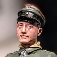
Wrapped the cockpit up today, it was pimped up with extra bits from a Mustang, Spitfire, and Lancaster, with the seat harness both American and German. Also it was a last minute decision to leave the pilot out, I’ve been wanting to get back to putting pilots in my models so I’ll use him instead for my USAF Skyraider build I have planned…2 points
-

Metallic Details News (LSP)
Bill Cross and one other reacted to Metallic Details for a topic
Gloster Gladiator. Cowling and engine (ICM, 1/32) Set contains 3D-printed parts for detailing of cowling with engine for the aircraft model Gloster Gladiator (ICM).2 points -
Metallic Details News (LSP)
Bill Cross and one other reacted to Metallic Details for a topic
Pratt & Whitney R-2800 late (1/32) Set contains 3D-printed parts for detailing 1 engine of the aircraft.2 points -
The finished IP. Not bad at all, if I do say so myself.2 points
-
1/32 Eduard (Hasegawa) P-40N Warhawk "Klawin Kitten"
chrish and one other reacted to Tolga ULGUR for a topic
Some progress2 points -

Revell 1/24 N-1 Starfighter
BGB and one other reacted to The Madhatter for a topic
hi everyone Hope we all had a nice relaxing Easter break? Not much to report on this one as I am waiting on some more paint to arrive as I couldn't stand that splotch on the front panel - so I stripped it right back and repainted it. Not the whole ship - just the front section Did a dry fit of the engines and they do look good. I just need to wire in the filament but due to the complex way Revell have you put the whole lot together, it's going to be a challenge to say the least Well, that's it for now. She's sitting on the shelf awaiting the new paint. Once that's here, I should get her finished pretty quickly - I hope. In the meantime, I am working on my HMS Exeter which I'm hoping to have done for Expo Thanks for your patience and I'll see you again soon Si2 points -
*** Finished*** 1/32 Trumpeter P-47D-22 "Kansas Tornado"
Azgaron and one other reacted to Tolga ULGUR for a topic
Some progress Fuselage painting terminated. Next step is decalling2 points -
1/16 scale scratch built AT-38B Talon-The Smurf jet is back!
Derek B and one other reacted to Pete Fleischmann for a topic
Thanks for checking in- slowly getting there…2 points -
I don’t know…. I tried researching BC a few years ago but not very seriously, there’s a Bonham Carter family in Dorset but not sure if they’re related. Later: it seems not.1 point
-
SAR missions north of the DMZ had a serious threat of Mig harassment. A mobile, or quick release air to air radar unit was designed and developed to mitigate this threat. More then a few Mig pilots found themselves on the unfortunate end of the Superbolts sting. Hugging the valleys and canyons they were fast, nimble and difficult to detect. It wasn’t uncommon with the aid of a airborne EC-121 Connie’s help to set traps for unsuspecting MiGs.1 point
-
Would a Devastator in pre-war colors qualify, lower part of the wings are stll silver? Stefan1 point
-
The next step was to protect the decals and existing paint work with a couple of heavy gloss coats: I used Alclad's Aqua Gloss, which I generally reserve for those occasions where I'm concerned that a solvent-based clear coat might affect the decals - which is the case whenever they're laser-printed, like here. I'll leave this for at least 48 hours now, before going anywhere near it with masking tape! I've also discovered some errors and omissions, some of which I also plan to attend to. The most visible one is that I got the colour of the engine pylons wrong. I assumed they'd be white like the engines themselves, but they are in fact the same light grey as the wings, so I'll be attempting to correct that, at least. Might get a chance to do a bit more work on the Welsh kit now. At least I know not to bother with the Corogard decals! Kev1 point
-
Have been busy working on classic cars, motorcycles and aeroplanes of late - but, with the nights drawing in here, I've been back to the bench. A little side-track from working on the interior: I wanted to see how the fitting of the wing spars/gear bays and initial ribs would go, as the instructions are very clear about not gluing anything until you have all of this loosely fitted. The instructions then have you carefully bonding everything in place on the lower wing moulding in one go - being careful not to impart any warp in the lower wing. The 'wheel' sections of the undercarriage bays were assembled and bonded to their adjacent rib, before laying everything in place (including main spar) on the lower wing and checking fit. All good, so I bonded everything in place with 'Quick Drying' Tamiya Extra Thin solvent - working out from the wing centreline on each side. Whilst everything drying I wanted to check everything was correctly aligned, so removed the upper-wing sections from their sprue and dry-fitted in situ. Fit against the lower wing/wing internals was very good, so happy that the internal structure was straight. And I couldn't resist a quick dry fit with the fuselage - just to see something a little 'Spitfire' shaped... Back soon... Iain1 point
-
I have some great progress to show you - it's been a very good day for the P-51 project. After a bad day yesterday. Not long after I posted this pic: I got busy preparing the Rhino dataset for print, along with my updated smiley face casting, and the newly designed exhaust stack. Here is a shot from the slicer software (Chitubox): This print job took 11 hours to complete, simply due to the height of the cowl part. 11 hours. When it finished at about 9 PM last night, and after waiting for it all day with bated breath, I found almost immediately that the nose didn't match up properly to the prop spinner. OMG!! It suffered a local deformation just like my early prop spinner did. I show no pictures - it's just too sad. Otherwise it was perfect. instead it is unsalvageable - scrap. The other parts (smiley face, and exhaust stacks) looked great. So at about 11 PM, I had another print job ready with a re-oriented cowl. I do not have a picture, but it was oriented straight up, not tilted. That is how I solved the prop spinner deformity problem. I let her fly at 11 PM, and at about 10 AM next morning (today), it finished. And viola!! It is about as perfect as I could ever ask for: I sweated bullets about it, but the re-orientation worked. Note it is hollow. That is a good thing, as this part is very large. Keep in mind, for those of you who think the exhaust cutouts are too large, that this part is going to be skinned in aluminum. And the final shape of the cutout will be the edges of the aluminum panels, and correct. You can see the faint panel lines that I am going to use to trim all the aluminum panels. What a relief, after 22 combined hours of printing. The other parts: The previous smiley face test part had raggedy edges; this one does not. It's as good as it can get. I designed the exhaust stack in about four hours in Rhino. Just like the drawing. So easy and so fun, after the nightmare wing-to-fuselage forward fairing, the radiator intake, Malcolm hood, and windshield top part. Very very hard. ModelMonkey has 1/18 exhaust stacks too, nice ones, but these were easy enough to do and were compatible with just how I want this thing modelled. Close ups: Let's see some dry fit action with the prop (which has been sitting around for a while now): I am so tempted to go ahead and skin this thing now, finish the prop, install the stacks, and paint/weather it. But the more patient modeler would wait. First things first right? And, I still must make a final decision as to which subject I will model. Will the nose be blue? Or yellow? Blue has alot of momentum behind it....Cripes A Mighty! This is a large milestone because the engine cowling part is the first truly large 3D print part. And it has to integrate with other big parts, in this case with the firewall, forward fuselage side panels, windshield panel, and wing leading edge beams. The first of many large complicated parts. Now what to do next. I might do that Malcolm hood test part - needs to happen. And of course - more surfacing behind the radiator. Later!1 point