Leaderboard


Popular Content
Showing content with the highest reputation since 06/04/2025 in Posts
-
Well Kev, it’s time to hit the deck This auspicious date is perfect to announce what marks the start of the next journey for airscale. The Defiant kit is selling so the venture is a success in my eyes, meaning I will take a chance on another subject in what I dream will be a long line of new exclusively 1/32 kits The Typhoon, the brutish, powerful, hedgehopping, unrelenting powerhouse that didn't whisper death from above; it announced it with violence – especially after D-Day. I chose the car-door version, both because I think it is more atmospheric, but also because I thought the transparent parts would be easier to manufacture – bubbletops are hard and have seams…. that said, the centre section is modular so assuming there weren’t many/any other airframe changes it could be done afterwards Key with this kit is the partnership with Typhoon Legacy, where Ian Slater and team are restoring JP843 to fly. As mammoth a task as could be imagined so I wanted to help. A healthy % of the sale proceeds will go towards that. The kit will feature JP843 before her conversion to a bubbletop as one of the options. I am keen on suggestions for other options too, especially any that were in non-standard or interesting markings. I have also been working with Arthur Bentley whose drawings and CAD knowledge have really helped kick-start the project. So here is where we are at… the cockpit is virtually complete, the remaining structure about 90% done but not ‘kit ready’ and the surface detailing less than 50% ..and a few coarse test prints to check a few things.. I would anticipate another 4 -6 months of development / production and welcome any and all contributions to this thread so we, together can make this something to fill the gap in the market. We are off again Peter48 points
-
Hello, everyone! Long time, no post. After completing the "panzer of the river" dio back in February, I've started a few things but struggled to get anything across the finish line. Happy (very) to report that this one is done. It fought me most of the way, but by the time I'd gotten really frustrated with it, I was too far along to pitch it. That said, I'm more or less happy with the result. The decals have me fits and you'll see quite a bit of silvering which is just super frustrating. I opted for decals as I wasn't confident that I would be able to get masks to lay down in the wing corrugations. Turns out the decals didn't feel like doing it either. Oh well. I was really geeked about the Devastator kit when it came out, but in my opinion, Trumpeter managed to put out an aggressively mediocre kit. In that regard, I guess Trumpeter managed to capture not only the form of the real airplane, but it's whole vibe too. So, kudos to them on that front, I guess. (?) Anyway, the fit was okay in general, but I had it in my head to really detail up the interior, only to find that it's really really spartan. The whole bomb aimer's area is just pure fantasy and doesn't line up with any of the reference photos in @Dana Bell's recent book. So, it made it a real challenge to want to try to do any extra detail work on the interior. I suppose in the end absolutely none of it would be seen anyway, especially with the wings folded, but I would have known. That said, I did use @airscale's PE and 3D printed products to add detail where I could. I can't recommend these highly enough and they're almost a requirement in my opinion. Off the top of my head, I used the interior set, the prop, wheels, gunsight, wing fold, and twin .30 mount. All fit pretty well without having to do much fiddling with adjacent parts and the added detail was/is lovely. Thanks @airscale! I ordered the ASK stencil set as the kit-provided stencils are ridiculous. However, I would also suggest that the ASK set is only slightly less ridiculous as they are rife with spelling errors and their instructions seemingly have you placing them randomly around the airplane. Weird. I used the Gold Medal decals for the aircraft markings and, fortunately, they came with stencils and much more plausible placement instructions. Any issues with them laying down on the model are mine, not theirs. Highly recommend the Gold Medal set. Also, if you don't have Dana's recent TBD reference book, just buy it. It's a fascinating walk through a really weird, esoteric, and utterly mid aircraft. I digress. This is my rendition of T-14, George Gay's aircraft from VT-8 on the day he became the sole survivor of his group's attack on the Japanese carrier fleet at Midway. If anyone's not familiar with it, here's a short primer on the whole thing. https://en.wikipedia.org/wiki/VT-8 Enjoy!37 points
-

Father-Daughter Project
Rick Griewski and 36 others reacted to Greif8 for a topic
Hi, my name is Ani and my dad said I could show some pictures of the magic house we built together. It took 6 weeks to finish and my dad and I worked on the house every evening when he was not working somewhere not home. My dad showed me how to use different glue to glue parts together and he helped me to glue some of the harder parts. He also showed me how to use different kinds of sanding things to smooth the wood parts so they fit better. I was sad that my magic house did not have lights like some other houses that I saw but my dad said we could make our own and he helped me put little lights in the house and garden after he drilled some holes or made little spots on the wood to fit the lights. He showed me how to use a tool to make grooves in the wood for the electric lines and then we joined the lines from the lights to the little battery packs that my dad had in one of his model parts boxes, he really has a lot of those. I am happy that the magic house turned out so nice but I am happier that my dad helped me and we had a lot of fun together. I really love my dad and we like to make things or draw together and I hope you like the pictures of the magic house.37 points -
Salut tout le monde ! Mon dernier projet est terminé. Le modèle ICM est très bien conçu ; il manque juste quelques détails. Pour cela, j'ai utilisé des pièces photodécoupées Eduard et Aims. Un peu de rivetage sur les parties métalliques. Peinture Vallejo. Et quelques masques de rondelles pour l'aile inférieure car ICM s'est trompé sur les dimensions correctes ! J'espère que vous aimerez ma Charité . Malte, été 1940 Merci.35 points
-
Last evening and today is when I got to enjoy the fruits of my two-year labor. Buckle up - I have many pictures to show. First, before I proceeded to fuselage join, there was the exterior rear-view mirror, and the pitot mast. These items were easy to Rhino design, and printing was straight forward. Take a look: I am pleased with the mirror, and it is not as wimpy as the mirrors I made for Miss Velma quite a while back. Never-the-less it is just one more item that begs to be broken off. This model is just "festooned" with fragile parts that are easily broken off. Handling it presents the constant risk of breaking something. It's nerve-racking. When done, I will display it and leave it alone! BTW, you are going to see in all these pictures that the Malcolm hood is in various positions. I do that just to show off. I am so proud that the hood can move, I just have to show that it can. 🥰 And speaking of fragile parts that beg to be broken off - the pitot mast: 3D printed of course. The early P-51's had a long mast like you see here. The -D has a much shorter mast. Why? And then - I just flat ran out of things to do before fuselage join. So fuselage join: What a huge Mustang! Look how it dominates my messy modeling table. It bumps up against everything - my foam wing tip protectors were vital! My heart was racing. I was careful as a heart surgeon doing this join, and my 3D printed round support tool was helpful maintaining a (fairly stable at best) upright stance. It was just such a position where the landing gear post breakage catastrophe occurred a month or so ago. Perilous moments for sure, but no problem this time. Once joined, I could bond on the main gear wheels/tires with flats properly oriented. And then it was on to the MLG strut fairings, or strut gear doors, which I have been patiently waiting for for a very long time. They are part of the signature look of the P-51. This is what I wanted: My Rhino MLG door layout, with deadly accurate kinematic geometry, taken directly from the engineering drawings. Needed to assure the gear doors are hanging as they should. Here are the parts (for the LH side), which have been waiting a long time: Installation of the RH door was straight forward, although very delicate work. But the LH door - I had long ago broken off one of the clevis lugs inside the wing which position the top of the door. So I had to jury-rig a couple of crude locator tools to help. And here are the results: The above picture includes the uber-scary repair of the LH gear strut, broken off last month in the most calamitous mistake of the entire build - a build that had plenty of calamities. I can make out the repair, but I hope nobody else can. I am happy with the gear strut fairings. And for new-comers, this Mustang has mismatched tires. On purpose. Also - that last picture shows the results of the big rake angle adventure, which took up lots of oxygen in this thread, and was a many-days-long hand-wringing affair. I think we have a correct rake angle here; let's hope it stays that way.... Once those doors were installed, this model was 99% complete. Lacking only these: Those bomb racks are from Model Monkey - I ordered them along with the rudder pedals and WM seat quite a while back. These racks are beautiful, and appear quite dimensionally accurate - I think I am going to use them, and you will see them installed next post. I am undecided whether or not to make 75 gallon tanks for this kite. But for now - let me flood the zone shamelessly with Cripes a' Mighty pictures: That, ladies and gentlemen, is a 3D printed 1/18 scale P-51B - a two-year effort. She is not perfect by any means, but by god she is dimensionally correct in all respects. Hope you like what you see. Next post will be about the bomb racks, and then I think it will be time for an RFI. Thanks all of you for supporting my effort on Cripes A Mighty.35 points
-
Hey guys, here are some pics of the Revell F/A-18F Super Hornet…, not the best kit, but if you stick to the manual and test fitting over and over again, here and there some mental breakdowns, it’s possible to build it….🤨 Decals from DXM Decals, centerline fuel tank from RESKIT, pilots from Academy…32 points
-
Hello all I've pretty much completed my Academy 1/32 F-4E. Finished in RAAF '70-'73 livery when Australia leased them, awaiting the F-111. This puppy took quite a while to get right. The Academy kit is a rehash of the Revell, so, yeah, not good but currently the only game in town for a F-4E. The kit was little more than a usable basic shell, which was fine because that's what we do. I figure it took 3 weeks alone to manufacture correctly seamless engine intakes. I cut and drooped the ailerons, opened the engine cooling doors and ordered all the usual suspects from Reskit and Aires. Let me know what you think Cheers32 points
-
Riding the momentum, I finished riveting the fuselage. This time I did things a little bit differently. I taped the fuselage together and drew the vertical rivet lines so that the rivet lines would meet at the seams. Again, the surfaces were sanded and a pastel wash was applied to check the work. There were some errant rivet lines that need to be filled and re-done but I can soon move on to fitting the cockpit into the fuselage and gluing the fuselage halves together. Just for fun, I taped the riveted components together and took some photos before the parts are cleaned off. By the way, the wing to fuselage fit at the wing root looks great doesn't it?32 points
-
Hey everyone! So, for a change, here's a Bf 109 G-6 in 1/35 scale from Border Model. Honestly, I think it’s the nicest large-scale version of this plane out there, I couldn’t get my hands on a 1/32 kit, no shop had any in stock. This Border Model kit is really great: it’s got the right shape, very accurate, packed with details, and super easy to build. The only real issue is the decal sheet, it's mostly incorrect and doesn't even include decals for the instrument panel. So I picked up an IP and some pilot harnesses from Eduard. As for the decals, I tried an aftermarket sheet, but it turned out to be even worse than the one from Border Model… Thankfully, my Silhouette Cameo saved the day. The only decals I actually used are the yellow "87" triangle on the left, the stencil under the exhausts, and the round stencil in front of the "1" on the right. Everything else was done with masks: the 8 crosses, the '1', the "-", the JG53 emblems, the victory marks on the rudder, the little red triangle on the left just behind the spinner, the manufacturer’s plate behind the supercharger intake on the left side, and of course the spiral on the spinner. Here’s the link to the WIP: Bf 109 G-6/U2 - 6./JG 53 - Border Model 1/35 - Works in Progress - Large Scale Planes This kit was a real pleasure to build, and I’m looking forward to hearing your thoughts and feedback on it. Denis. Now, on to the pics!31 points
-
 Hello, everyone and welcome to the arena as I step into the ring with the ultra-short-run Infinity Model D3A1 Val dive bomber kit. I think some of my frustration with the Devastator I recently posted was that I came into it with the expectations that, being a modern model from a generally decent manufacturer, it would be a decent quality build. Perhaps I brought that on myself as I've done enough Trumpeter kits to know what to expect from them. Anyway, I'm hoping that by setting my expectations ultra low with this short run offering from Infinity Model, that I'll get a bit more enjoyment out of this build. As I've mentioned a number of times, I'm a bit of a junkie for the early to mid-war campaigns in the Pacific. Maybe it has something to do with my grandfather having fought with the 32nd Infantry Division in the Buna campaigns, maybe it's because picking up a book about the Battle of the Coral Sea in kindergarten (yes, seriously) was what sparked my now lifelong passion for WWII. Whatever the case, my hands-down favorite aircraft subjects are birds from the SW Pacific theater. With that in mind, I stashed the Infinity Val and some of their indigenous add-on stuff a few years ago and, despite my devastation over the last kit (get it?) I decided to test my patience even further with my next build. So, join me as I try to beat a short run kit into submission and turn out something of a halfway decent result. So, what shall we be building? I'm not super thrilled about the kit's offerings as they're all Pearl Harbor aircraft and that's not a huge interest to me. So, I started poking around the web and, as has so often been the case, landed at pacificwrecks.com where I came across this story. What a crazy tale - check out the link for the full thing, but essentially 3 Vals got lost, ran out of gas, and landed on a beach on the south side of New Guinea. The crew then went on the lam, fought off search parties with MGs pilfered from their aircraft, and were finally wiped out in a running gunfight. With a story like that, I couldn't not build it. Happily, pacificwrecks also includes a profile that gives an idea of paint scheme (though they used a D3A2 for the template despite it being a D3A1). So, off we go. Grab your towel, put on your boxing gloves, and let's fight. The workbench, all neat, organized and ready to go. Not pictured: mouth guard, spit bucket, and referee. Here are the add-on parts I bought back when the kit first came out. All except the mask set are from Infinity directly. It kinda chaps me that they'd put out a kit with a high price tag, then charge more for these add-on items, but they're not the first and they won't be the last. And hey... it didn't stop me from buying them. Anyhoo, we have the engine set, bomb set, instrument panel "set" (one tiny fret of PE), and exhaust set. The PE frets in the top left are included with the kit and have things like seatbelts, gunsights, and arming propellers for bombs. These all look pretty nice, so here's to hoping they're worth the investment. The first step has you build the IP. Miraculously, I was able to shave off the raised plastic detail without winging my thumb in the process (an altogether too common occurrence). Later, I'll punch out the individual decals for the gauges and install them that way. Should be a hoot. At least the IP went together well, though there's really not that much to it. Just a few knobs and such get added to give the final piece some 3D relief. The PE seatbelts went together remarkably well and actually look pretty good. They'll be a challenge to paint in their current positions, but I actually prefer painting them in situ, so I'm used to that method. Generally speaking, the detail on plastic parts is soft, locator pins are more an idea than reality, and in many cases you're left scratching your head about how things are supposed to fit together. Then, when you do figure it out, it turns out the mating surfaces of the two parts are roughly the size of a pin head. In short, there is currently equal parts superglue and plastic cement holding this thing together. Here the pilot's seat is installed and the bulkhead in place. Nothing is dry fit. If you see two parts together throughout this build, they'll either have tape, my fingers, or glue holding them together. Dry fitting isn't a thing here due to the aforementioned lack of locator pins. I spent a good chunk of the morning getting the interior around. You have to place each of the ribs individually and none of them fit all that well, so that was a bit tedious, but not overly challenging. Oddly, the curve of the rib doesn't match the curve of the fuselage. So, I had to tack one end down with superglue, set it with accelerator, then run more superglue under the other end of the rib so that it would conform to the fuselage. I realized later that the vertical brace (horizontal in this pic) roughly amidships is glued on too high. Its base should sit flush with the raised detail just forward of it. I ended up having to nip off the part that sticks out the top. In retrospect, my placement idea was dumb, but in my defense the instructions are... less than clear here. 😕 Either way, test fitting proves that my gaffe isn't visible with the fuse halves together. I was actually pleasantly surprised with how well things went together. Make no mistake about it, I had to shave off things here and there to get stuff to fit or to sit flush, and there was judicious amounts of superglue and accelerator applied, but it was more or less straight forward so far. Not "kit for beginners" straight forward, but if you've got some modeling moxy, you should be able to tackle this. Test fitting the cockpit to the sidewalls shows a fairly decent fit. That gap between the floor tub and the sidewall will be impossible to completely hide, but it likely won't be very visible with the thing buttoned up. I did have to shave the sides of the rear tub piece a lot to get them to fit against the fuselage side cleanly. Same pieces, but from forward. I finished out the night by installing the gunner's seat and test fitting the fuse halves together. Like some others who have built this model, I added a small support to the underside of the gunner's seat because otherwise, it is only held in place by the single vertical strut that connects to the two arms that project from the seat frame. If that's the way it was in the real airplane, that strut must've been made of titanium or there was a really low weight requirement on gunners because that was just ridiculous. Anyway, you can see it fits fairly well and there's a decent amount of (admittedly soft) detail here. Sorry these are vertical. I'll adjust them before I upload them next time. In any case, they give you a feel for how things go together. Before I get too much further, I'll likely add some small tabs below the cockpit floor to help stabilize it, then add some tabs to the fuse halves so they'll line up somewhat cleanly. That's where we're at today. I did test fit the fuse halves and was, again, pleasantly surprised with how well they fit together. That's (emphatically) not to say that they fit well, they just fit better than I expected. It looks like the spine for the vertical stabilizer will require a ton of filling and I'm only partly convinced that the firewall will go in with anything resembling accuracy, but that's future me problem. Tomorrow, I hope to prime, shade, and paint the interior. I doubt I'll get it done tomorrow, but I'll try to post a decent update in the next day or two. That said, I have a couple days off next week, so maybe I'll manage to get the fuse closed up by next weekend. Then it'll be on to the wings, which promise to be an adventure. And there's the bell. Off to my corner.31 points
 -
Here is my Curtis’s Helldiver, out of box, except the PJ Production figures and HPH metal dive flaps…30 points
-

Revell 1/32 Hawker Hurricane IIb
D.B. Andrus and 29 others reacted to Grizly for a topic
The aircraft represents, "Butch the Falcon" flown by 402 Squadron. As the title sez, the model is based on the Revell kit with a little Eduard in the cockpit, 3D printed bomb pylons and 250 pound bombs, custom stencils (the AE Q) and custom decals (the serial number and nose art) which complement the kit decals. Camouflage paints are all Xtracolor enamels with Tamiya acrylics for detail parts and Alclad II for the matte finish. An excellent kit.30 points -

Westland Lynx SH-14D - Revell 1/32
Daniel Leduc and 28 others reacted to Rob K. for a topic
Hi, My first post on LargeScalePlanes, since I usually build 1/48 and the occasionally 1/72 models. Please find the Revell 1/32 Westland Lynx in Dutch service. The kit was converted to a SH-14D using the Mk 88 and HAS 3 boxings. The kit rotor was adapted displaying a folded rotor blade configuration using the Scale Warships conversion set. The port side engine compartment was opened up and a resin engine added. The dummy torpedo was modified with detail added, using parts of a 1/48 A.M. Avenger torpedo. Although, perhaps an unlikely weapon combination, in addition a machine gun with platform was added to the starboard side. The machine gun was used in some operational situations. (Ref. YouTube search for: boardingteam Tromp Taipan) Since the 1/32 Dutch Decal Lynx sheet was unavailable, I asked Heli Scale Quality to print the decals for me. I supplied various images and they delivered. The decals are now available on their site. Paints by MRP. Hope you like it. Rgds, Rob29 points -
The riveted parts were washed with soapy water to remove as much of the pastel wash and sanding dust from the rivet holes and panel lines. I can now start to assemble the previously painted cockpit components and install them within the fuselage. Here is the Aires instrument panel sans gun sight glued onto the front bulkhead. The seat and rear bulkhead were glued in next. The sidewalls have been temporarily taped into place to serve as position guides for the front and rear bulkheads but I didn't want to glue them in yet as I am concerned that the top edges of the sidewalls may not sit flush against the fuselage interior. After placing the cockpit tub between the fuselage sides, I can see that there is no problem with the starboard sidewall so I can glue that one into place. However, the top edge of the port sidewall does protrude too far from the fuselage interior. This one is glued into place with less glue, hopefully giving it enough flexibility for me to push the sidewall onto the inside of the fuselage. The cockpit tub is then glued into the port fuselage side, with lots of CA glue on the sidewall so I can stick it into place. After that, I can glue the fuselage sides together, using Tamiya Extra Thin cement. As typical on these aircraft models, the view into the cockpit goes bye-bye.29 points
-
Actually they are somewhat useful at times. The rest - just trying to be cute. They are scaled pretty well, so gives the viewer another indication of the size of the component in real life. For instance - this post! Last post I showed pictures of hard-fought-for Rhino models of forming blocks for the empennage fillet fairings. They printed up nicely: Now to put them to work. Here I show one of the eleven fairing details sitting on a form block after using it to form and trim the detail. It was exceedingly difficult to form with its two compound curved valleys. Heavy-handed work best done on the form block; not on the model. Add faux fasteners, and it is ready for installation. Here is the first of the eleven details bonded onto the fuselage and empennage: Wahoo!! As you might guess, not an easy forming task either. And then after a couple days of hard work, I got them all finished and installed. I am reasonably satisfied, not absolutely thrilled mind you. I took full advantage of the welded seams defined on the drawing as an excuse for some less-than-perfect butt joints at the severely curved edges (three places). It's the best I could muster methinks. Take a look: The form blocks have done their job, and are now relegated to my ever-increasingly populated bone yard. Those fillet fairings had been on my mind on again and off again for months. One of those things to wring hands over. They were small, tough to handle, and finicky - but they are also done. Actually, as I near the finish line, I do not think any of the remaining tasks are as challenging. The elevators, rudder, and tail gear doors should be more straight forward. And they are next. So stay tuned as we run the last lap or two!29 points
-
hello chaps thank you for the wonderful response - I had hoped it would be welcome news I think your persistence & longing was a large part of the decision Max also like that Tangmere idea a lot - this was my first thought - I know nothing other than it doesn't look like any Typhoon I have seen.. Thanks Dennis - all of those are in my wheelhouse I did look at the Battle but it is bloody huge so thought I would save that ambition for later thanks Andy - any details and suggestions are welcome - I did talk to Chris Thomas about a Desert scheme but he was a bit concerned about it as he has never located 'adequate photo's or drawings' - I mean I found this one, but for all I know it is in a bleached temperate scheme ..did you swoon Kev? thats all that matters to me now that is the highest compliment I have ever been paid and makes it all worth it completely untrue, but I like it anyway thanks Will the cockpit is indeed a challenge - in 1/32 and in 3D it is quite a fragile structure so would need to be super tough resin like the tough Defiant parts. There are also a number of assembly options that all have pro's and cons including what you are looking at which is all the framework is one part, but it is quite a job to minimise (& remove)the supports but make sure it is not compromised. I also tried having the side tubular structure in the fuselage halves with cross pieces and haven't discounted it, but it's not preferable.. thats pretty much why I started a WIP as I don't profess to be an expert so by showing and trying I am sure ideas will flourish I got a slot to test print a few bits, my iphone takes crap pics so I bought a camera but it's not here yet so apologies for the quality.. one thing I will say is IGNORE THE LAYER LINES I deliberately print at 70 microns so I get parts out quickly and spend no time at all thinking about orientation so as to get clean 'grain free' surfaces - these are just proof of concept prints to validate details, shapes etc and are whacked with mr surfacer to see what is going on.. the prop and spinner.. ..happy with that, no further work needed.. ..tailwheel.. ..same - happy with that.. ..tailplane.. largely happy, the elevator even has pop rivets with holes in which I think will come out with a wash, but you will see the trailing edge while nice and sharp is wonky behind the outer hinge - likely a print problem, but that is the sort of thing these are supposed to flush out.. other than that, happy days... ..now these are interesting parts as they are the proof of concept for the IM clear parts.. here I am looking for shape issues and fit - in fact the kit will feature both types of rear canopy - this type with the aerial and the later type with no framework as this is what JP843 the subject had.. in this pic the windscreen is a test where I want the part to sit in a hole in the fuselage, not on top of it. This is because it's the only way I can see where the shaped fairing into the fuselage can be represented and as long as the fit is super clean there is no seam to fill.. ..the upper canopy has two vertical triangular supports to align it with the windscreen to test the forward join which actually is excellent the parts are just resting on each other as there is actually a structure between the front and rear sections.. ' hinging that part (or at least showing it open) is another problem to solve and may involve a moulding for closed and one for open - i hope not as thats more bits and more cost... ..the door will likely be 3D with acetate glass to keep scale thicknesses.. otherwise, that bit seems to be going well.. ..the gear bay.. ..lots going on here actually - the wing and bay are ONE part / one print - I don't want a join at the dihedral break which brings its own problems, but this way, there are no seams anywhere and the anhedral (yes it did) and dihedral will be perfect.. that said one problem I have seen with the Defiant is the concept of fewer parts means less value for money people feel so i need to tread carefully.. in terms of fixes here - the spar structure by the gear mount is missing so that needs supporting properly, the framework at the rib should be straight so that has been corrected already, and the obviously over sized gear mount, but there is not a lot I can do about that.. there is also an odd flaw in this print where there is some kind of artefact running through the spar to the gear mount - you can see one end of it sticking out at the wing root.. that is corruption of some sort in the slice file or something, but other than that I was very pleased that the spar, all the ribs, the pipes and the rivet detail all came out well and most importantly the wing itself is strong (it's hollow) and the right shape with great surface detail (not finished yet) so the one part for a wing experiment was a success I hope the process is interesting, and if nothing else it keeps me busy posting as I am building absolutely nothing at the moment... TTFN Peter29 points
-
Hey, here is the A-10C Thunderbolt II from Trumpeter… Vacu canopy, GT Resin and Olimp set, TwoBobs Decals and Master Gatling barrel and pitot and other bits and bobs…. In all pylons and external stuff are micro magnets, so everything can be taken off ore repositioned…26 points
-

F-16A Netz-TopAces
Antonio Argudo and 25 others reacted to Pete Fleischmann for a topic
Here’s a few scenes from my Tamiya Netz conversion in progress Aires main well Mini Craft Collection seat Tamiya pit, Aires Glareshield, scratch IP, Quinta details. The Aires pit is actually atrocious. The entire thing sits way too far aft. Vertical fin modified with Hasegawa fin base and Quick Boost flare dispensers Aft deck A model details/Archer rivets MCC canopy internals Bandit Resin Factory captive AIM-9 Flight Line Resin ACMI pod Scratch IP with TopAces configuration. Set on Aires pit..which I did not use. Craptastic. Final result there…minus HUD obviously cheers Pigfighter26 points -
I've done the flushing. Weathering is almost complete. There will be gunpowder fouling and a couple of places to accentuate. All the little things are done. Now it's all gonna take off. )))).26 points
-
Thanks Mal and Ernest for your messages. The underside of the 109 is done. I'm taking the chance to snap some pics now, because there are a lot of really fragile bits that could easily break, so this 109 is definitely staying on its wheels for good... Better safe than sorry!26 points
-
The basic decals are done. There are a few small ones left and you can varnish and flush.26 points
-
Just a brief update... things seem to be coming together quickly. The nose and tail section fitted extremely well with only a small amount of sanding required. To be fair, I did trial fit them as a semi-way to hold the fuselage halves together so I wasn't expecting any problems anyway. Where I did have a problem is with the wing joints. I knew Tolgar had the same issue and I couldn't find a way to remedy it... ... but they fill easily and won't be a problem. Again a similar issue with the tail... the fuselage interferes with the elevators. Not sure if this has now been corrected in the 1/32 kit but it is a simple job to drill out and file. I did wonder about the outer wing fit tolerance being too tight but with a small amount of sanding the wings slotted in perfectly. No messing around with dihedral... it is all just perfect - and having spend much of my time fussing around trying to get "classic" Airfix kits wings right I can only say that this kit is a dream! She has wings!!! Can't wait to see how it looks in black! Thanks for looking.26 points
-

***Finished*** 1/32 Fisher Models - Hawker Sea Fury FB.11
Philbucknall and 25 others reacted to Tolga ULGUR for a topic
And the finish26 points -
Another rare one here. Let’s go swept wings . (And right, no one makes an injection molded kit in 1/32) Tigger made a vacuform kit and I think some effort to make a 3D print is out there somewhere, idk. Anyway, I’m feeling up for a challenge much in the spirit of the Vigilante. Probably no 3D. Possibly rob parts from a 1:32 Thunderjet . I’ll do a take on the plane’s history tomorrow . Isn’t she beautiful though? The plan is to surface model it with epoxy clay. To keep it reasonably light,I’m building a balsa subframe under the epoxy clay. And I’m pretty confident I can final surface it with aluminum tape. I don’t think this is going to be mind blowing in detail, but should still present pretty well much like my Fury.25 points
-

HK Models Do-335A-12 at Oberpfaffenhofen
Reuben L. Hernandez and 24 others reacted to jeroenpeters for a topic
I've always loved the look of this huge Do335 with the US soldiers gazing at it and swarming around it like ants. For the base I used a very high res US map from 1945 that I had printed on canvas and then... cut it up. No decals were used. All masks. Lots of Eduard and Master upgrades and a Tamiya Jeep with Alpine figures. I could have gone all out on the weathering, but I didn't.25 points -
And I've finished the build at last. After starting in December 2023 it's rewarding to see this one across the finish line. I really enjoyed the kit a lot, from cutting the first parts off the sprue to positioning the landing gear indicator rods today. Like all Zoukei Mura kits that I've built (this is number five) I've learned a lot about how the actual airframe came together. This kit isn't without its challenges but with careful planning and dryfitting I can recommend it highly. Here's a few photos before the RFI post. Cheers, Tom25 points
-
1/32 Short Stirling
mc65 and 24 others reacted to tomprobert for a topic
Afternoon all, My modelling mojo has deserted me of late, but I have had the beginnings of a return the last couple of days, so fancied doing a bit more to the Stirling. A while ago I made all the framing for the bomb aimer’s windows from Evergreen, as the kit supplied parts are completely the wrong shape and the plan was/is to add my own glazing. Thankfully, and despite the incorrect shape, I have been able to use parts of the kit supplied clear parts, carefully measuring and cutting them one by one: They were then ‘dropped’ into the framing using Formula 560 canopy glue, with the edges neatened up and sealed with Milliput Black. The end result isn’t too bad and once the whole area has been blended in with a top coat of paint, it should pass muster from 50 yards! I’m leaving the centre panel right until the end as a means to remove any bits of dust or stray debris - plus I need to make the bomb sight mounts which will be very fragile. Another job ticked off… More when there’s more. Tom25 points -
Hi all, First build here for over a decade and I'm not the most proficient modeller but here goes. You all know this one I'm sure And here's where I am with the kit and using the Eduard Löök set. Kit detail is soft but usable. Everything brush painted with Humbrol acrylic after base coat of rattle can silver. Been working on the fuselage to wing joint, there's quite a large step that I've traced to the undercarriage bay and wing tab thickness Finally, some subassemblies That's it for now. Helpful tips and comments appreciated!24 points
-

P-51 D Revell 1/32 + Life Like Decals
Castor and 23 others reacted to Daniel Iscold for a topic
One less box at the stash. Hope you like it fellas!!!24 points -
Thanks guys! I decided to take an unorthodox approach to wing attachment. Based on prior dry-fitting, it looked like the wing root fit was really good so I decided to establish that joint first. There is a lot of surface area to work with so I was confident that I could get a strong bond but I took some extra time and did one wing at a time. Filling and sanding at the wing root is much more difficult than other areas so with this joint as clean as I could get it, work to bring it up to snuff will be minimal. There is a small hairline gap on the port side but that can easily be addressed by smearing in some Milliput. After the glue securing the wing tops had fully cured, I can now attach the wing bottom. The spar part ensures the correct dihedral and so I used some OG Testors tube glow on top of the spars and then fused the outer circumference of the wing joint with Tamiya Extra Thin.24 points
-
Workshop update First of all, thanks for the very good reception of this workshop. I am glad that it has aroused such interest. I hope that I will not disappoint your expectations. Okay, that's enough of the introduction, time for the report. Progress on the cockpit continues steadily. I haven’t built a machine like this in quite a while, so on the one hand I feel that great excitement that comes with trying something new, and on the other—some hesitation in taking the next steps. Fortunately, I’ve got a detailed painting plan that focuses on recreating the textures and colors of the materials used in the original cockpit structure. Naturally, everything will be enhanced with tonal variation and weathering to convey a sense of long-term operational wear. My Duck represents a spring 1942 aircraft—after months of intense duty. By that time, the airframe would have shown heavy signs of use, and that's exactly the look I'm aiming to achieve in the model. After several sessions of careful color layering, I’ve prepared the base metallic surfaces of the cockpit components. What you see in the photos is almost a complete set—still missing are the pilot’s seat (awaiting belts), the observer’s bench (which was mounted in the float), and a variety of wires and tubes that will be added later. The metallic finish was deliberately exaggerated—complete with discolorations and chips. This layer will receive a primer coat followed by the final color applications. That means I need to think ahead now about how these early effects will appear once partially obscured by later layers. Before moving on, I had to carefully determine what colors should go on which elements—control column, rudder pedals, radio units, and so on. This part took several days of comparing photos, footage, and talking with other modellers. Once that was sorted, I was finally able to start masking. With such a complex assembly, it’s a tedious task, but well worth the effort. Wherever I could bring some contrast to a part, I went for it. For masking I mainly used tape and liquid mask. Once that was done, it was time for the primer—Yellow Zinc Chromate. The result can be seen in the photos. That’s it for today. Lukasz24 points
-

1/32 Infinity Models SB2C-4 Helldiver
rafju and 23 others reacted to monthebiff for a topic
So while cleaning up the wings after assembly I've also turned my attention to the engine which needed lots of clean up also but so far so good Pretty happy so far but adding ANYZ connections to the collector ring was a bit stressful drilling however many 0.6 holes through just over a 1mm ring of plastic but slow and steady got there As well as the cylinders with spark plugs in place Also started work on the propeller blades, these are pretty poor with lots of flash abd poor shape around the base but more importantly missing the cuffs. I initially thought I would use some 5thou plastic card for this but decided that would probably be a bit messy so decided to mask up and use a few layers of primer/filler from the spray can and a final coat of Mr Surfacer 1500 Should maybe have done 1 or 2 coats more but I'm happy with the way they look and no glue or anything to clean up. Regards. Andy24 points -
Weathering the hull is uncharted territory My guidelines are: - I know I don't want to see much rust stains below the flotation line, which differs from the colour demarcation line - I need to find a way to discolour the hull under the flotation line. the flotation line weathering is remarkable - I would like to add a little bit of barnacles but really minimum. - I have seen different weathering on WWII pictures. Some boats are pristine, some are heavily weathered. I want to depict mine quite weathered but not like she stayed in a drydock for years. Here are some examples illustrating the above: Here's one pretty beat up above the floatation line, proving you can go overboard if you wish Discoloration of the hull below the floatation line is obvious in this dry dock picture, not an easy effect to achieve Discoloration also happens on the dark grey/blue above the floatation line as seen above This one is probably not representative because it's been out of the water for very long, but I found the moss interesting illustrating the barnacles effect I would be tempted to achieve (bit less though) I'll use only a few products for weathering the hull: Both the naval wash and steaking effect which is brown rather than grey will be used randomly together alongside the hull. Once a bit dry, it will be rubbed with a sponge for effect Salt streaks will be next. pulled vertically but more patchwork under the flotation line. These will probably disappear with further treatment, so basically just a first encounter with this product (which can be replaced with any paint well thinned or even oil paint; It's just more convenient I confess. The area just under the ballast gets a heavy grimeline which is then blended out The difference between weathered and unweathered is quite visible. I'm not too much concerned at this time because I knwo more treatment will be added later on and i'll correct what I don't like doing while testing new grounds. The model is huge but it's easy to work section by section Rust streaks are added above the flotation line with the oil brusher which is again just quite convenient. I also like to use any default in my work to simulate damage on the model. So here the plastic was scratched and I used that just like if the real boat was scratched at that same place. rather than fixing the damage it's a good way to have simulated damage random. The ongoing process rest streaks on the bow, rust paint is applied in dots, left to dry and then blended downwards with a thin bruxh controlled with more or less thinner happy with the result under the floatation line so far Next: discoloration under the floatation line and I have been thinking about how to do that for the whole week Thanks for following24 points
-
I've managed to apply the side markings--a little touching up to do but I'm pretty pleased overall. After this I'll be going back and modifying the fin markings to remove the RLM 76 which didn't appear on this aircraft from the one clear photo I've come across, then adding the stylized "5" to each side of the front cowling and the "2" on the leading edge of the wings. Cheers, Tom24 points
-
1/32 Hasegawa Grumman Hellcat F6F-3
AngryJazz_Models and 22 others reacted to Tolga ULGUR for a topic
New start: I hope I don't ruin it23 points -

DH.9a Ninak (Post War), Wingnut Wings 1/32
D.B. Andrus and 22 others reacted to AngryJazz_Models for a topic
Here are the finished model of the Wingnut Wings DH.9a Ninak. I went with the boxart version. This would have me change a few things I haven't tried before - like moving the stitching and using the PE version + making the cutout for the observer. This was also the first 2 seat biplane I have built. Apart from a few mistakes, Im very happy with it 😄 Thank you all for the motivation along the way!23 points -
..another milestone, the IM fuselage blank is complete for assessment by the mouldmakers.. ..there are many new rules of design I am not sure I have met yet, but this after weeks of work is at least the start.. clearly the cockpit needs cutting out and many other structural bits need doing, but the area there needed to be thin for all the cockpit structure..plus all the surface detail needs doing of course.. ..we will see, I will probably have to completely redesign it Peter23 points
-
Thanks for the comments! The build has crept to a crawl as I'll be taking a break soon. The rudder has been glued onto the tail. The main thing that I worked on this week was this joint between the wing bottom and fuselage. There was a slight gap here so I've welded a segment of stretched sprue in the gap as a filler, keeping mind that the joint will be re-scribed after cleanup. After sanding, the joint was rescribed and rivet detail restored. Some new rivets have been added to the wing bottom in this area but have not been highlighted with a wash so they're hard to see. Tomorrow I'll be leaving on a medical mission to Mozambique so this build will be on hiatus for about two weeks. See you when I return!23 points
-
My humble contribution! The modeling world will be poorer without them! And in very slow progress!23 points
-
Here's the problem with the double row riveter out of the box. I want the two wheels to rotate in unison, so I took the tool apart and used CA glue to fuse the two wheels together. It was a surprisingly fiddly affair trying to get the points on the two wheels lined up. The photo is obviously BEFORE the modification. After that fix, I was able to get on with the riveting of the upper wings. The lines I had drawn a few days ago were traced over with either the single Galaxy Tool riveter or the new double line rivet tool. Here are the riveted wings after sanding and a liberal coat of brown pastel wash. A simple tip for those of you that have the Galaxy Tool rivet tool. After gouging countless lines into the model by accident, I finally modified the tool to help prevent this. Oh, and I added shims to the outboard ends of the flaps to eliminate the gaps.23 points
-
Thanks Troy for your message. I’ve been wrapping up the final steps. I sprayed a coat of semi-matte varnish (super important, because MRP’s matte varnish is way too flat, not great for a plane on the European theatre), then used a light grey watercolor pencil to add some wear and tear around the engine cowl, the wing roots, and on the wings. I’ve gotten used to working with a light grey pencil (instead of silver or aluminum) because it just looks more realistic in the end. Once all those little pencil marks were in place, I sealed everything with another layer of semi-matte varnish. I took off the masks on the three canopies and wrapped it all up by making and gluing the pitot tube onto the tip of the left wing.23 points
-
Continuing the 'dry fit' theme - it would be rude to not slot the tailplane in place - that's how good the fit is! I've also reshaped the cross section of the rear fuselage a little so it's a bit flatter on the upper quarters on either side of the opening for the turret fairing: And try out the wings, rudder, rear decking and cockpit canopy - again - all dry fitted! Note that I've also modded the 'ears' on either side of the cowling part - they are now recessed, rather than proud of the surface: Really looking forward to getting the cockpit interior all painted up and assembled - it's going to look quite something... Iain22 points
-
Thanks Martin! Appreciate it! Thanks Matt! This happens on all of my builds since I like my aircraft all buttoned up. But like you said, I've documented the build with clear photos so the detail can be seen that way. Thank you! Thanks Jay! And yeah, I see some similarities with the P-47. Thank you! My wife's name is Jean but I am John! 😄 The fuselage seams were sanded and then given a thin bead of black CA glue to erase any gaps. Remember that tip I gave about the Galaxy Tool riveter? Well, as soon as I had modified it, I gouged the plastic immediately. Puzzled, I took a closer look and found that the axel hole in the rivet wheel was much larger than it was supposed to be. With a hole that big, the rivet wheel shifts up and down, bringing the supporting part dangerously close to the plastic. Since there was no way to fix the big hole and 1mm is my go-to rivet for 1/32 aircraft models, I ordered another 1mm rivet wheel and yup, it had the right-sized hole. I haven't touched the wing bottom yet and this needs some work. First I gave it a rivet job. The wheel wells are a bit bare, especially when comparing them to the real aircraft. The Eduard Exterior set for the Ki-84 has PE fascia for the wheel well walls. I also scratched up a couple of junction boxes. The first phase of the wheel detailing included the PE fascia junction boxes as well as some hydraulic lines using copper wire and some Anyz bits. The wheel wells were topped with some more wiring work. The corrugated line was fashioned by wrapping thin copper wire around a thicker wire.22 points
-
And so next would be the elevators. Like many aircraft of the day, the elevators are not shown/opposite parts, but the same part LH and RH. The RH part is just turned upside down. Here is my elevator kit of parts hot off the printer: You see two identical bodies, two identical tabs, two identical tip fairings, and two identical balance weight towers. Also identical tab pushrods. What you do not see are two identical tab "horn" brackets, which I made from bent-up .005 inch thick aluminum sheet - not fabricated at the time this photo was taken. Not sure if it was out of sheer laziness, but I chose not to do a build-up as I have done for other control surfaces. Instead a semi-solid body. So the Rhino modelling was hard, but the assembly much less involved. Assembled and painted: Note that I made some attempt at depicting fabric surfaces on the elevator bodies, with pinked edges too. The tip fairings are dry fit - I believe I am going to install hinge pins and have movable elevators, attached to one another at the root ends with a shaft that goes through a hole in the fuselage. To install those pins, the tip fairings must not be there; they go on later. And if it goes awry, I will just glue the elevators place. And the obligatory picture with elevators dry fit to the h/stab: What do ya' think? Now it is on to the rudder. It is more complicated than the elevators. Stay tuned!22 points
-
Workshop Update – The Duck Is Back in Action! Progress has been steady, so it's time for another workshop update. As I mentioned earlier, I’ve focused all my attention on the cockpit. It took me a while to map out all the cockpit wiring. The Duck was quite well-equipped with radio gear and other onboard systems. The cockpit looks surprisingly modern for a 1930s airframe, though much of the cabling along the sidewalls remains visible. I really wanted to capture all that wiring accurately. To avoid the constant hassle of delicate wires breaking loose, I decided to drill all necessary attachment points in advance. I used micro drill bits ranging from 0.2 to 0.4 mm, depending on the wire thickness and placement. While working on the pilot and observer’s floor panel, I accidentally wore down much of the surface rivet detail—there’s a lot of it in that area. Since this part is quite prominent, I first tried to restore the rivets partially, but eventually decided to re-rivet the entire panel from scratch. A lot of work, but absolutely worth it in this scale. Once all components were ready, I laid them out for painting. Since the entire construction is resin and metal, I used a black primer with a 1500 grit finish for good adhesion. From there, I started building up the surface tones layer by layer—a time-consuming step, but one I really enjoy. Next up: detailing the cockpit gear and starting the first weathering passes. The Duck is slowly starting to come to life. Thanks for reading, more soon! Lukasz22 points
-
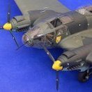
So the "Godfather" has delivered as promised, so with his blessing, here's what arrived in the post this morning, all courtesy of Peter @airscale: Weighted wheels and the correct 5-spoke centres, I was tempted to fit the centres but it's such a precise fit that I feared I wouldn't get them out again for painting. Three-bladed prop as featured on the earlier car-door Typhoons: Each blade has a "key" which fits snugly at the correct angle in the hub. I love the fact that the spinner is hollow and separate, it gives options with the diorama that I have in mind. Main wheel covers, two part and just beautifully made: Everything is commendably thin....sharp edges! And the tail wheel....ahhh: Light years ahead of anything that has been available before. And the main undercarriage legs and supporting arm. I have done a quick trial fit on the MDC Typhoon, a flat filed on the round top will give a snug fit thank you! So first impressions of what Peter is planning for his Typhoon are, not unexpectedly, very favourable. I'm very grateful to him for taking the time to print these for me, it's going to add a lot to my CMK+MDC+Revell car-door with Modelu+Hornet ground crew! I have just started the camouflage on the wing tops, maybe some pics of that tomorrow.22 points
-
A couple years ago I went to the Australian Armor and Artillery Museum in Cairns, AU. Here, I discovered that tanks look much more impressive from the ground level than they do if you're peering down on your little 1/35 creations from above. So, I resolved to change my style of photography to make them look bigger and more alive. Imagine you're waiting in your trench with no more than a bolt action rifle and your wits... any blur... is intentional. Maybe they don't see me. Or change your perspective: You're now accompanying infantry: I tried to use some incense sticks to make smoke, but they didn't amount to much. Of course, no pictorial is complete without those detail photos: Those grills... the originals were unimpressive looking plastic. so, I milled them out, and replaced the solid plastic screens with brass mesh which had a scale hole size of 12MM. A friend gave me a PE set for another KV, but the sizes were all slightly off. so, I could only use parts. Which was ok, because all tanks look better without skirts. \ This has been my heaviest and best directed effort at weathering so far. At least five courses of oils as well as two courses of enamels. Chipping. Focused Rust. And of course a little bit of bare metal. The tracks and road wheels all got a lot of 3d dirt made of PVA glue and pigments. But because of the darkness of the tracks it doesn't show up too well. ...and I didn't want to use light dirt, because this tank is supposed to be in Ukraine. The legend "Kutusovets" means "Like Kutusov" or "Of Kutusov". Kutusov was the Russian general who fought Napoleon to a standstill at Borodino, and then chased him out of Russia. Anyway... thanks for looking, I hope you liked it.21 points
-
thank you for your considered points of view chaps couple of things - firstly only the wing surfaces (incl. belly) and fuselage halves will be injection moulded - absolutely everything else will be 3D printed. I have indeed spent a lot of time thinking about it and doing my research, some of it one of the world's best kit designers so I am comfortable the output will not be 'a limited run kit' kind of vibe - these will be IM parts of the highest quality if I design them right. in fact Brett Green had this to say about their last production "Although this is still technically a limited run kit, the quality really is very good. The plastic parts are well moulded with no sink marks or other obvious flaws. Flash is minimal Surface texture is particularly good. The fuselage accurately depicts overlapping panels, while the rest of the kit features crisp and consistently recessed panel lines and rows of rivets." That, with the quality of the Defiant clear parts is enough for me in terms of it being the right choice in terms of mouldmaker. In terms of why do it at all, I think that even though I did my best with the Defiant, there are (and will always be) layer lines - fine if you can have at it with a sanding sponge as there is recessed detail, but it is very hard to work around anything raised. that, plus my inability to get clean mating edges AND surface detail in the same print (I got one or other in testing) means for the end user - you guys, IM parts for the main structures is a win, win. All that plus I can make more means it is a compelling reason to redesign I will soon know if I was right or not, if my sanity lasts that long that is Peter21 points
-
well.... i am doing it - the main parts will be IM great for you guys, but sad for me - this lovely wing for example... scrap... weeks of work... ..I can use some of the design as templates, but IM has very specific rules for successful mould separation and surface detail, none of which is complied with in this design.. back to the drawing board.. I would love to, but that's even more design & complexity so to keep a reasonable timeframe I have not chosen to do open panels, or an engine - much as I want to clearly it is, surely...well maybe, well maybe not... I know what I want to do next which will be Biblical if I can pull it off Got to stay focused and get on with the rebuild.. Peter21 points
-
Crappy picture but slowly getting there ....21 points