
turbo
-
Posts
252 -
Joined
-
Last visited
-
Days Won
3
Content Type
Profiles
Forums
Events
Posts posted by turbo
-
-
Thanks Spyros!
Soooo, after saying how glad I was to get the wheel well detailing out the way, I've just come to the belated conclusion I can't progress much further without improving the flap area. I find doing fiddly PE and detailing work can be a bit mojo-sapping, so I like to break it up with other tasks. In this case, unfortunately, I need to address the flaps before the wing halves can be joined and I've run out of other small jobs I can use to procrastinate!
The kit has moulded ribs on the upper half of the wing, which is better than nothing but can certainly be improved if the flaps are to be modelled in the deployed position.
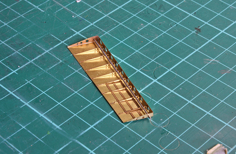
Fortunately, the Eduard exterior PE set has quite an acceptable solution. The first step, however, was to grind off the kit structures using my trusty David Union tool. No need to tidy up with sanding as the PE will cover all this.
Here's the Eduard PE replacement complete - I think it's a real improvement. The biggest challenge here was getting the ribs placed and glued into position. I found the best solution was to insert the kit metal axle part first then insert the ribs underneath it which helps keep them in place while you're doing the gluing with thin CA as well as making sure they're located properly.
And here it is dry-fitted to the upper wing. I'll leave it to the last minute before painting and joining the wings to glue it permanently in place so I don't do my usual trick and break something!
Edging closer to being able to close the wings up and feel like I'm making some progress.... -
Welcome aboard Phil and great start on the Mustang - looking forward to what you've got in mind...
-
4 hours ago, Phil Smith said:
Superb work here - fascinating subject!
29 minutes ago, dodgem37 said:Very nice.
Sincerely,
Mark
Thanks very much Phil and Mark, much appreciated!
2 hours ago, Gerhard said:I built the 1/48 version just ti try and get some Mojo going, and that made me looak the 1/32 version. What I see here I will never be able to replicate, but the kit has shot up om my To Do list. Really very inspiring work and an example to us all.
Thanks for the kind words Gerhard. You should definitely give it a go - the kit is great and up to Tamiya's usual standard (apart from the wheel wells maybe - they can give retractable undercarriage a miss next time!).
40 minutes ago, nmayhew said:yes!!
he's back!!
It's great to be back on the bench Nick!

-
-
-
Thanks very much Jeff, Ernest, Nick, and Zac, much appreciated!
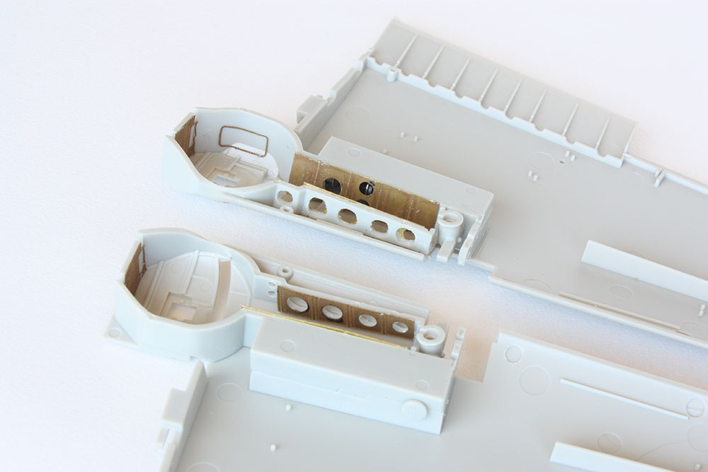
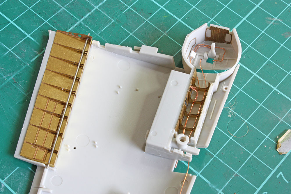
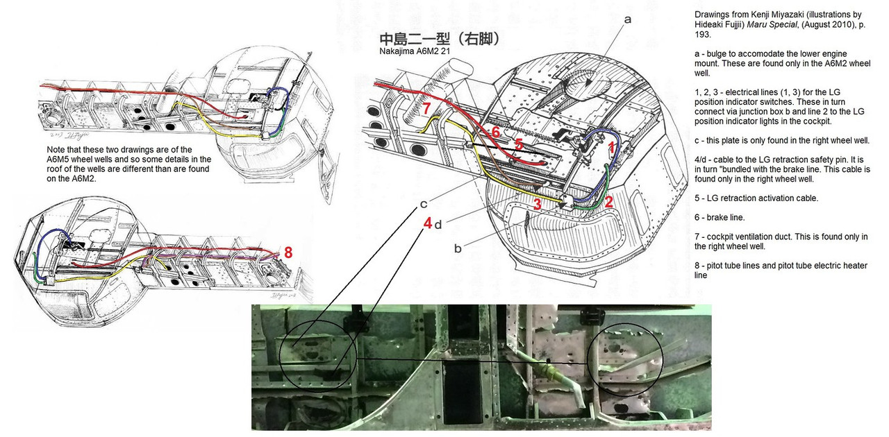
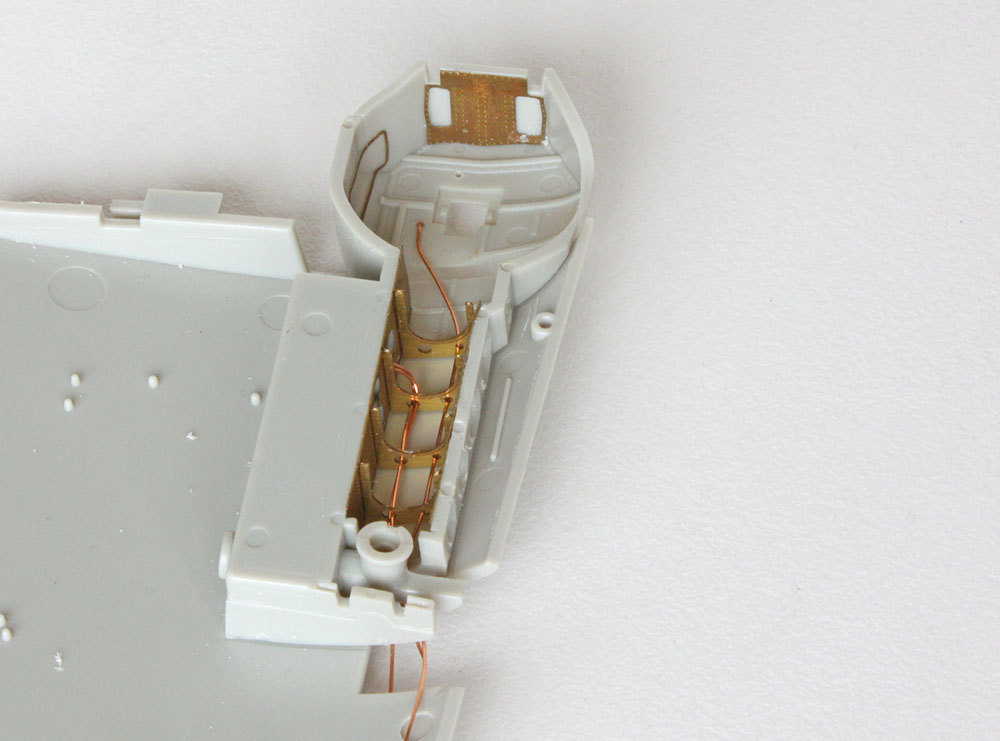
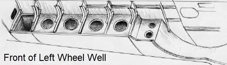
So, revisiting the wheel wells here's a reference picture courtesy of Ryan @A6M that I posted earlier but needed to reacquaint myself with. The 2 diagrams on the left are A6M5 wheel wells. The biggest challenge here (which is obviously why I stopped where I did!) is the cabling for the landing gear position indicator switches which runs into a junction box before being relayed to the indicator lights in the cockpit. This reminded me why I made the increased thickness plastic strip - junction boxes!
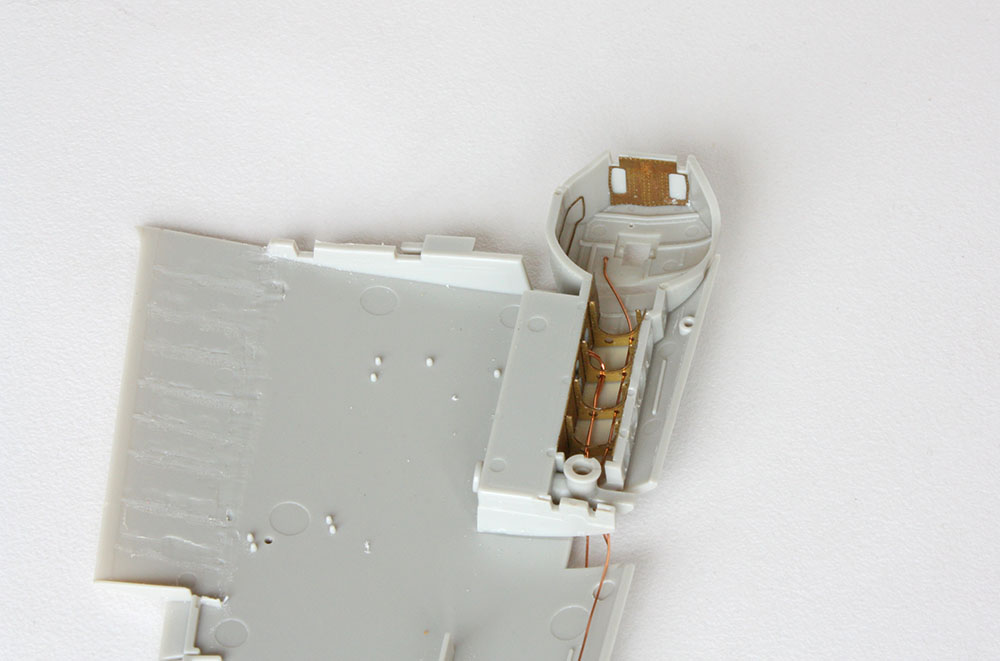
The junction boxes were fabricated by drilling holes to locate 0.3 mm copper wire then carefully sawing out the boxes from the stock plastic strip - fiddly work!
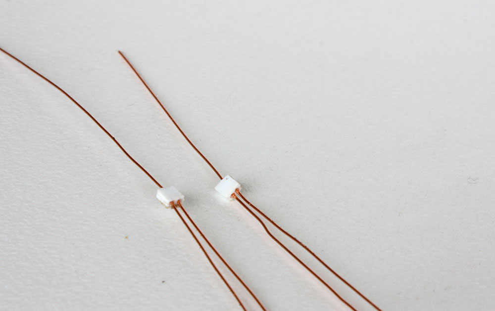
The wire was then cut to length and installed as best I could to replicate the cabling in the reference diagrams. Probably a bit over-scale but anything smaller was going to be too much of a test for my dexterity!
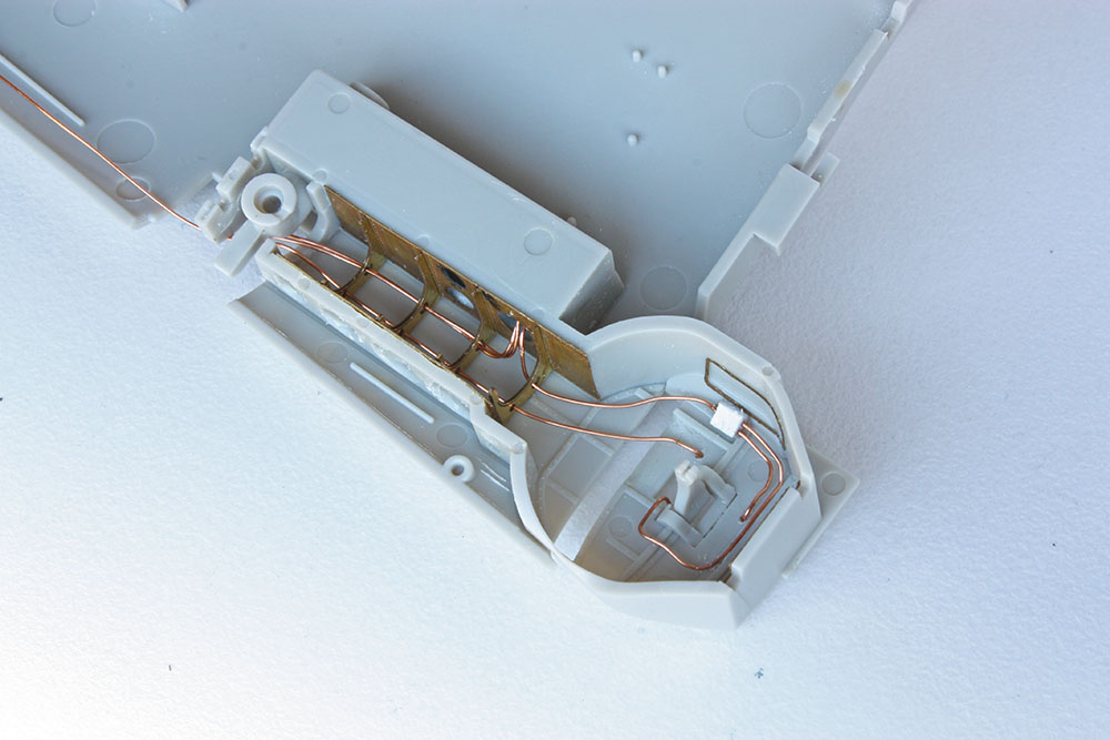
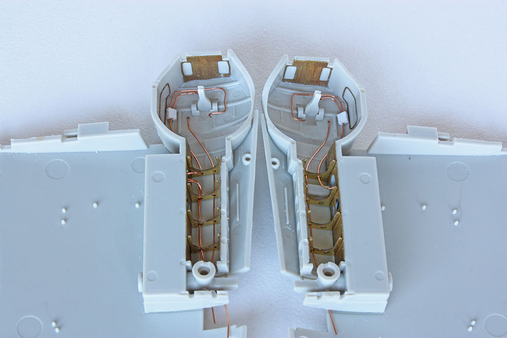
I've gotta say, I'm glad that's out of the way. All in all, the operation of drilling out lightening holes and fitting PE and cabling was fiddly and time-consuming due to the confined spaces and fragility of the parts once some supporting kit structures were removed. I think it was worth it in the end though as the kit-supplied detail here is one of the rare weak points.
Now, a question for Ryan @A6M if he is floating about or anyone else who might know. Were any of the junction boxes or cabling different colours or was the whole lot just sprayed over with aotake?
Cheers, Kirby
-
On 8/5/2021 at 8:41 PM, nmayhew said:
Hey Kirby
hope you are well
any more progress on this you can share?
Nick
Hi folks and happy new year! Wow, I can't believe it's been almost a year since I posted on this project. Work kept me off the bench pretty much all of last year, but I have now struck out working for myself so I want to create a little time for modelling.
The main problem with picking up a project like this is trying to remember what I was doing and why and the sequence of steps I had in mind - this is where posting on a forum as a record comes in really handy! I found this in the box so I had obviously installed the PE ribs into the wheel wells and started on the plumbing - more on this and some references shortly...
I also fabricated some additional thickness plastic strip and have no idea why!
I just dug out the references for the wheel wells and there may be a neuron firing as to the reason for this... -
On 2/15/2021 at 9:50 AM, chukw said:
Question: what is the long steel pin with the fine slot cut in used for? Thanks! BTW, I'm deliriously happy with my -400 and the 550 Elite- cheers!
You can feed the end of a bit of sandpaper into the slot and wrap it around the bit to use for sanding. Haven't tried it myself as have the D400.
- Troy Molitor and chukw
-
 2
2
-
-
On 1/12/2021 at 6:57 AM, A6M said:
Hello Kirby,
Here are the details on that vent system. The air intake’s location in the leading edge of the right wing can be seen in the drawing below. The vent had a cover that could be used to open up or close off the air flow.
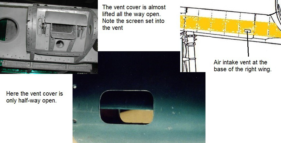
The cover was controlled by a T-handle on the right floor of the cockpit. The vent could also be pointed to direct the air flow as wanted. The air in the cockpit then would flow out through the hole in the canopy just behind the antenna mast.
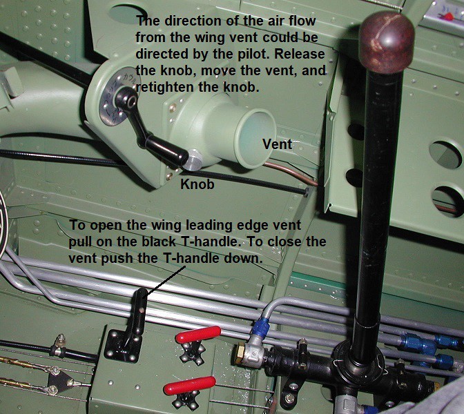
It’s really the same fresh air vent system as in a car (but without the added benefit of A/C).
Ryan
Thanks for that Ryan. With their usual attention to detail, Tamiya actually have a nice moulding of the closed vent intake on the leading edge of the wing. I might consider drilling it out later to represent it in the open position.
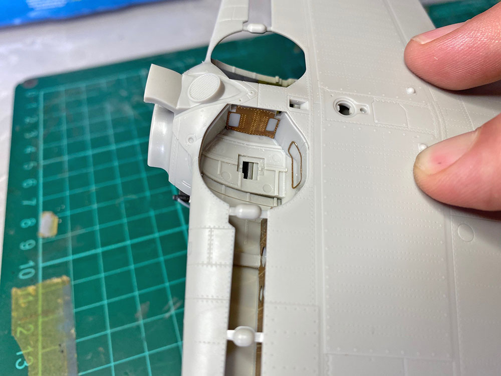
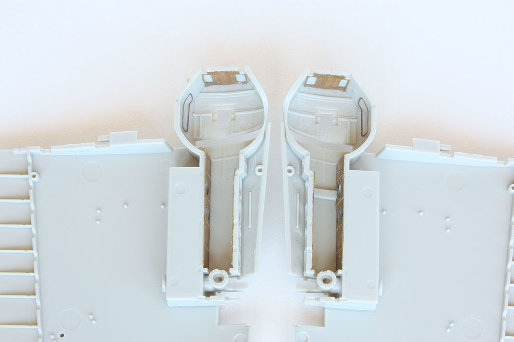
So, work on the wheel wells continues. Sean and Alex in their A6M2 builds and Ryan in his tweak list have all highlighted problems in this area, particularly if you are making some modifications. As I've mentioned previously, Tamiya have designed this kit to have retractable landing gear which has resulted in some compromises. In an effort to save space, the roof of the wheel well is made up of 3 sections - the wheel well part, the upper wing, and an intervening thin strip of the fuselage. The biggest design compromise didn't become apparent to me until I test-fitted it all together.
As you can see in the picture below, there is a large and ugly step between the wheel well part and the fuselage strip which, from the reference pictures above, shouldn't be there. This is not a fit problem due to some previous misalignment - all the locating parts are fitted perfectly - it's how Tamiya has designed it (including the inconveniently placed ejector pin marks).
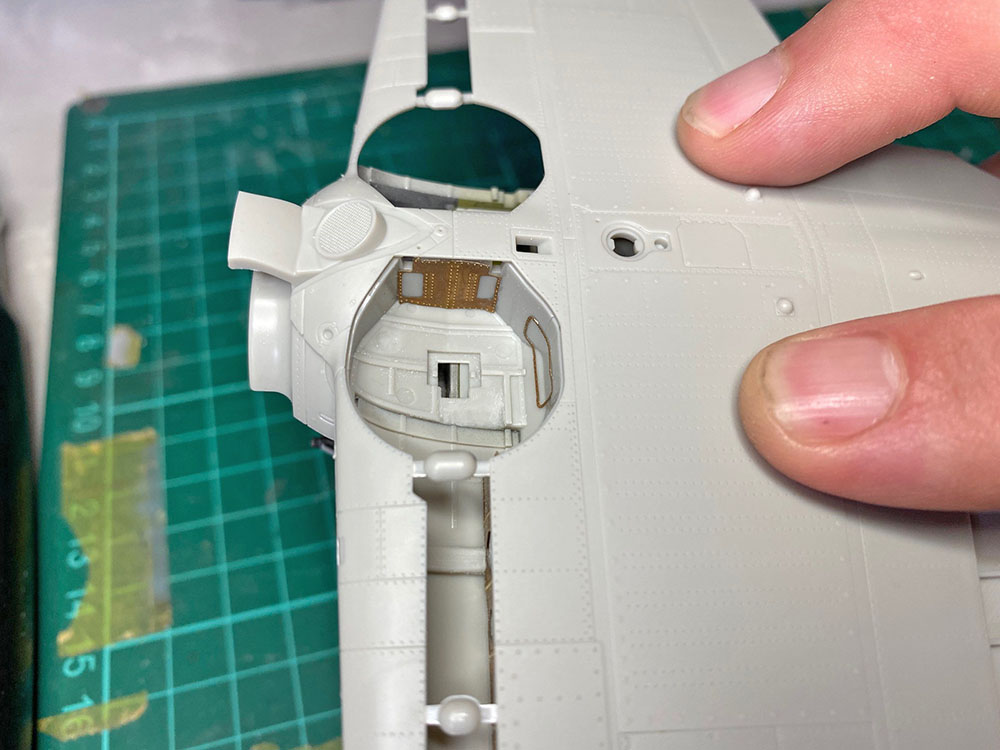
I couldn't live with this so ground and sanded the step down to something more acceptable and also made a start on eliminating the ejector pin marks. This all needs a bit more tidying up but is difficult as the area is not easily accessible. I also plan to obscure the offending area further with the electrical and brake line plumbing.
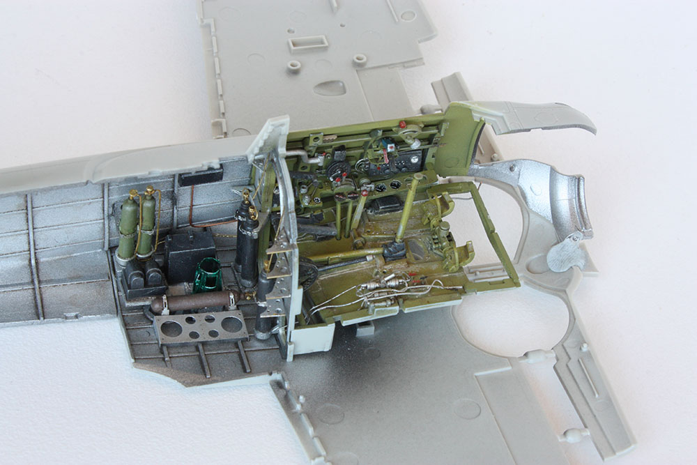
I somehow managed to complete the lightening hole and PE modifications to the port wheel well without breaking it at its weak point (phew)! At this point I decided to deviate from the kit instructions, which always makes me nervous with these finely tuned Tamiya kits.
I've had a lingering concern that adding the PE cross ribs to the wheel wells before installation could result in a subtle fit problem unless they are bang on in dimension and in my placement. Given the tight design tolerances in this area this is important, so my solution was to install the wheel wells at this point to ensure a proper fit down the track. The instructions would have you attach the wheel wells to the lower wing, but I felt attaching them to the upper wing would give me better access for fitting of the PE ribs and plumbing.
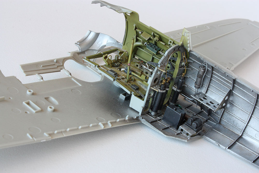
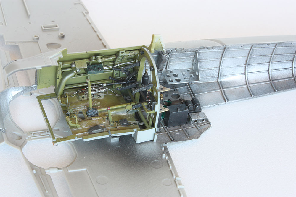
The wells were dry-fitted to the wing halves and fuselge and, once I was happy with the fit, Tamiya Extra Thin run into the contact points between the wells and the upper wing halves.
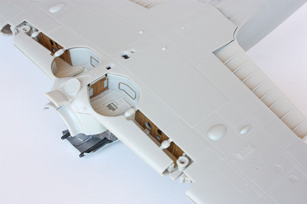
This should give me good access to fit the PE ribs neatly against the roof and install the plumbing and other detail. Then I just need to hope to hell that my dry-fitting was accurate and it all fits together properly later...
Cheers, Kirby
- Madmax, Rocat, scvrobeson and 13 others
-
16
-
On 1/23/2021 at 4:24 AM, Sepp said:
Well, I think we can safely say that you have the hang of this modelling lark
")
Seriously, though, it's beautiful.
On 1/26/2021 at 4:33 AM, Rod Bettencourt said:Great looking build!!
Rod
23 hours ago, Reuben L. Hernandez said:Beautiful! Simply Beautiful.
Thanks very much Sepp, Rod, and Reuben, the kind comments from folks around here certainly give me extra inspiration!
- Reuben L. Hernandez and Sepp
-
2
-
On 1/20/2021 at 5:19 PM, alain11 said:
Wow !!! God knows that we have already seen here and there many Tam's Corsair , but this one is well above the rest !!! well done !!!!!!
Alain
Thanks Alain, appreciate it!
-
On 1/18/2021 at 6:39 AM, Cicciuzzo said:
Very professional. STUPENDO
 On 1/18/2021 at 9:28 PM, dennismcc said:
Well I just had to bookmark this ready for my future Corsair build, great job, an extremely realistic finish.
Cheers
Dennis
On 1/19/2021 at 2:31 AM, Martin Kubis said:Excellent, this looks like the real thing!
On 1/19/2021 at 4:31 AM, AlbertD said:An inspirational build. Really well done.
Thanks very much guys, I appreciate your comments!
-
-
20 hours ago, LSP_Kevin said:
How did I miss this one? It's brilliant!
Kev
15 hours ago, Greif8 said:Outstanding build in all respects!
Ernest
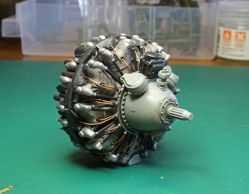
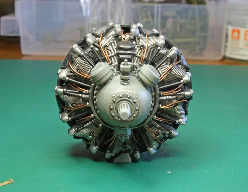
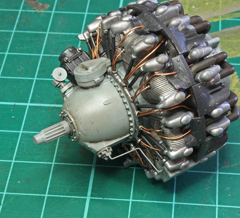
13 hours ago, MARU5137 said:Kirby ....
Your Engine is EXQUISITE.
and the weathering and overall build is STUNNING.
I love your Bent WINGY THINGY.


(there's a thread started where you can show your engines).
Thanks Kev, Ernest, and Maru, appreciate your comments! Thanks Maru for suggesting the engines thread, have posted the Double Wasp over there.
-
-
1 hour ago, MARU5137 said:
Kirby ,
I bet that Spectacular cockpit must have taken many hours
of work. Very detailed and can't tell the difference between
a real one to yours.
ASTOUNDING details and SO authentic.
PHENOMENAL.
KUDOS.
Thanks Maru, appreciate your comments! Yes, it took me many hours, more than I was planning. The problem is once I start adding detail I tend to get a bit carried away!
-
-
Great work John, I particularly like the weathering job you've done on the tyres - very convincing!
-
Hey guys, my latest Tamiya A6M5 Zero. Eduard interior set and some scratch building.
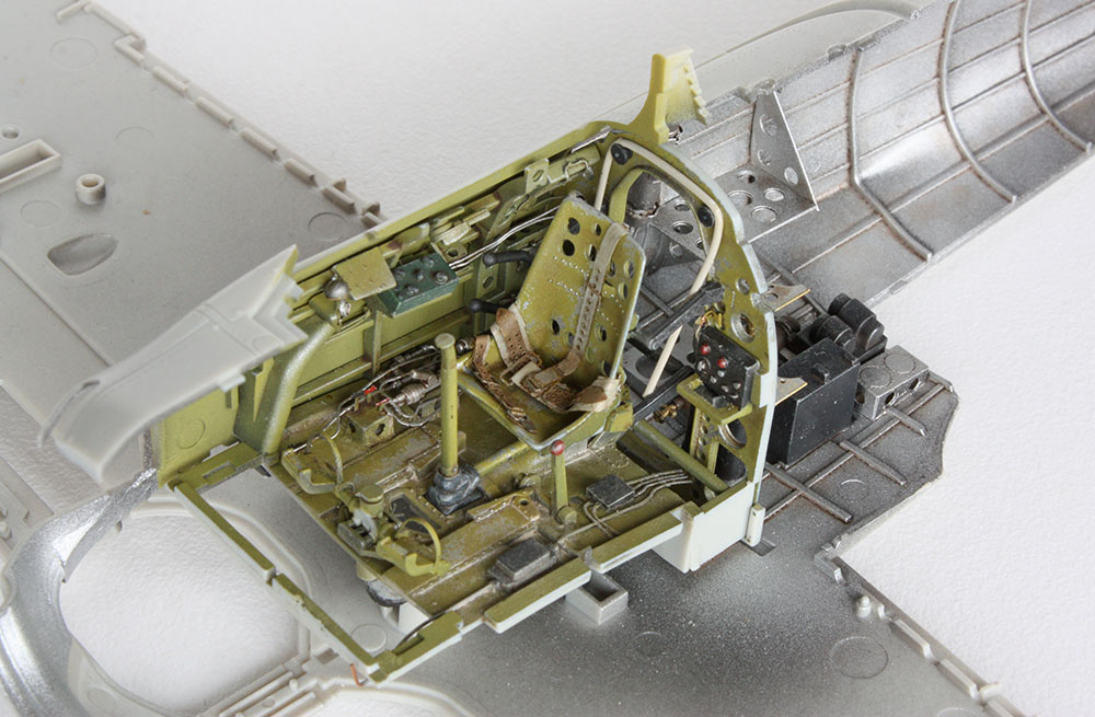
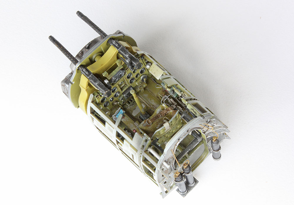
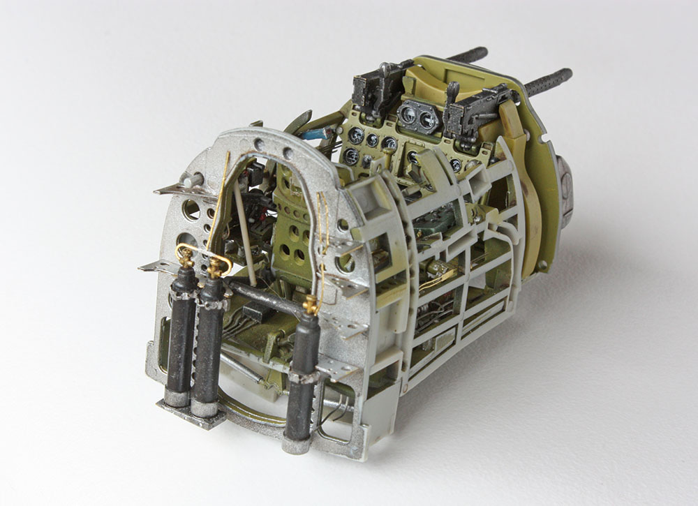
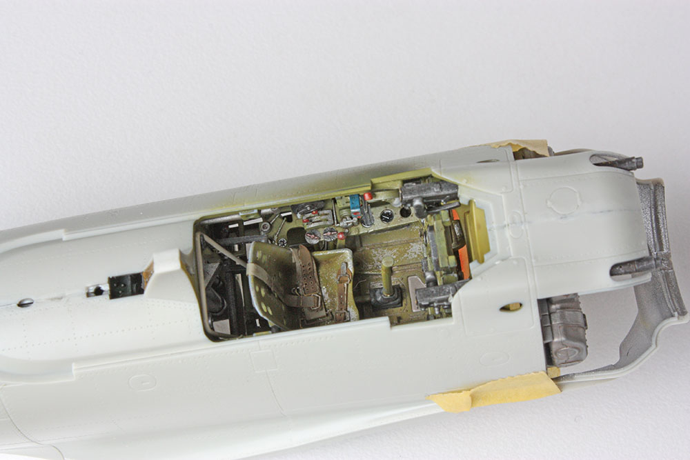
Cheers, Kirby
- Uncarina, Buster99, Model_Monkey and 11 others
-
14
-
On 1/5/2021 at 5:40 PM, Rockie Yarwood said:
Wow, just wow! Looking great, Kirby!
On 1/5/2021 at 8:39 PM, Jamme said:Hi Kirby.
Great job you're doing here.
Love it.
Cheers,
Jamme
On 1/5/2021 at 10:03 PM, dodgem37 said:Good stuff. Love what you're doing.
Sincerely,
Mark
Thanks Rockie, Jamme, and Mark, appreciate your comments!
On 1/6/2021 at 12:33 PM, Thunnus said:Great job Kirby! Trying to figure out if/how to use a given PE enhancement sets is one of the things that always ties me up. I usually end up with some sort of hybrid approach of using some but not all of the improvement set.
You're right John, my spares box is full of half used PE frets!
On 1/7/2021 at 3:45 AM, A6M said:I suspect the best approach would be to pick and chose the PE parts that would best enhance the kit. That would seem to be the ribs and the front face of the outer wheel wells. I don't believe i had posted the image below which gives you the details of the rest of the well.
There were some minor differences between the Mitsubishi and the Nakajima wheel wells, but these were mostly in the various plumbing lines were routed. The drawings that were posted are for the Nakajima Zero.
Ryan
Ah thanks Ryan, I was looking for a picture of the other wall - good to know the PE is accurate for at least one side!
So, after giving it some thought I've decided to use the PE enhancement on both sides of the wheel well despite inaccuracy of the lightening hole positions on one side because a) it will look significantly better than simply drilling the holes, and b) the PE ribs are designed to fit properly with both of the PE sidewalls installed. Either way was going to be a compromise but I think this is the best option.
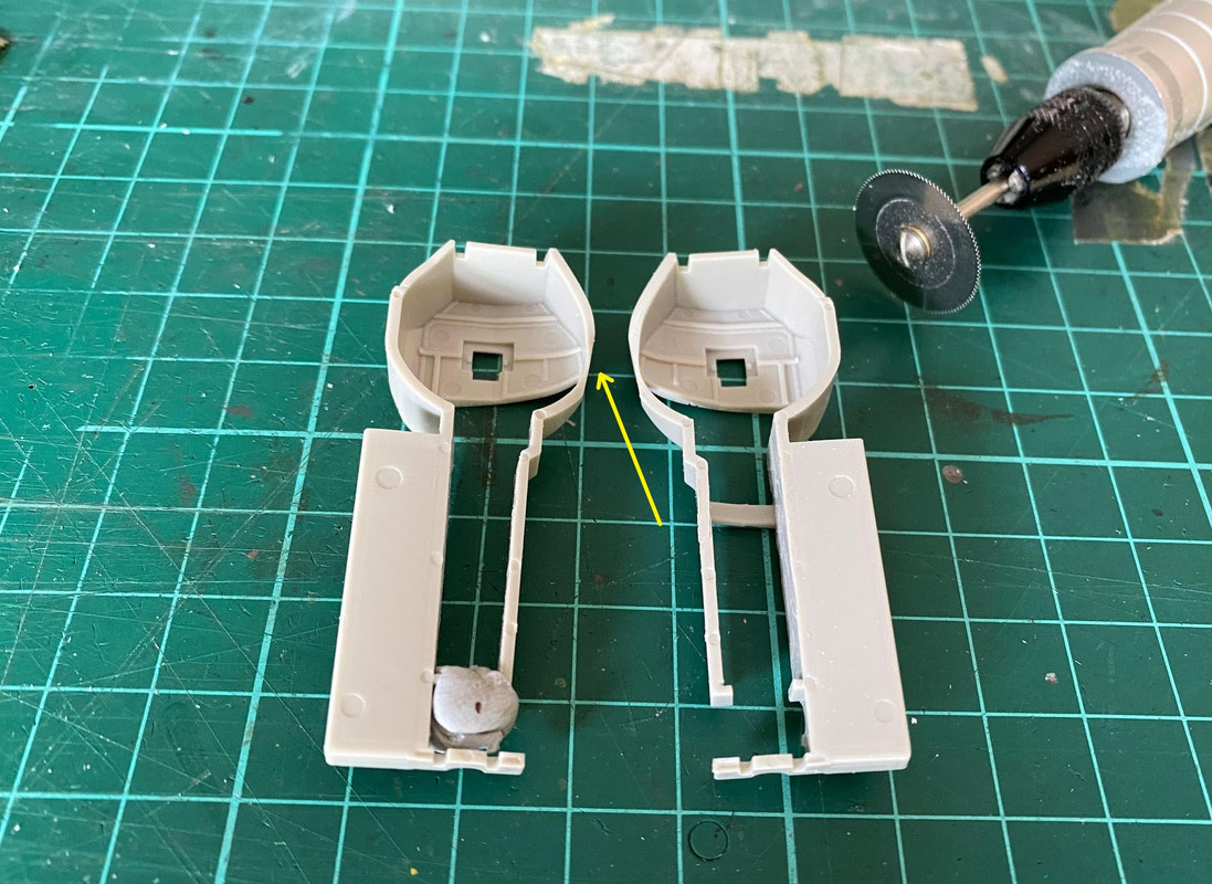
The first task was to remove the kit ribs and this where my new David Union rotary tool will earn its keep! Using the saw the ribs were removed in no time and tidied up with the grinder bit. I was careful to retain the cockpit ventilation duct shown in the pictures above which passes through the starboard wheel well (does anybody know where the inlet for this duct is?). This had the added benefit of retaining the structural integrity of the part as there is a very thin section of plastic (yellow arrow) on both parts which is going to be subject to breakage once the ribs are removed. I've tried to temporarily reinforce the port part with some blu-tak while I'm working on it.
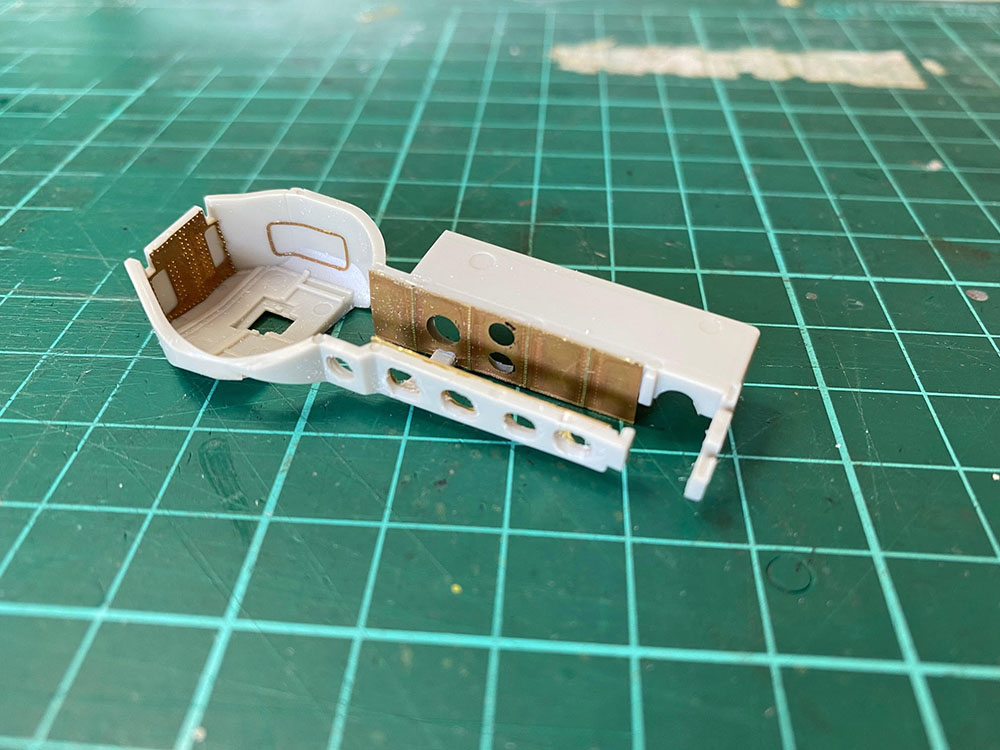
So that part was easy enough but it was about now I started to wonder whether I had made the right decision! Firstly, I needed to cut small notches in the PE parts for the starboard wheel well to fit around the ventilation duct. Once that was done, the PE parts were test-fitted and the positions of the lightening holes marked with a black marker pen. Drilling out of the lightening holes was a bit tricky due to access of the drill bit and I had to be careful not to break the part.
During test-fitting, it became apparent the PE parts are slightly wider than the kit parts. Whilst this would not normally be a problem, the wheel wells are designed to fit tightly between the wing halves, so the PE parts could potentially interfere with fit of the wing halves which would be a bit of a disaster! Another example of how making modifications to this kit can create knock-on effects elsewhere if you're not careful.
To address this, I temporarily fitted the wheel well to the lower wing and then placed the PE parts in position flush as possible to the wing before running thin CA in by capillary action to secure the part. I really needed 3 hands to do this and it took quite a lot of messing about to get it done, but it was necessary not to end up with a significant wing fit issue later. Thankfully test fitting of the upper wing half looks OK. Here's the starboard part so far...
I haven't done the port part yet and I'm not looking forward to it as I don't have the structural support on this side and think there is a real risk of breaking it with all the messing about that was required for the starboard side. Hopefully this is all going to be worth it in the end!
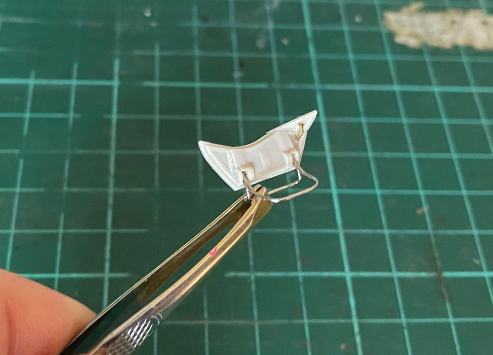
For a bit of light relief (!) I made some improvements to the inner gear doors. Riveting was added to the braces and the hinged corner of the door was removed with my Tamiya PE saw and posed articulated outboard with a PE hinge, which is the deployed postion accomodating the drop tank as per Ryan's tweak list.
I should add at this point that this kit is designed to have retractable landing gear (mine will be permanantly deployed) which adds some complexity to the kit and design compromises like this. I'm not sure about the value it adds really...
Cheers, Kirby
- Alex, Rockie Yarwood, Hartmann52 and 11 others
-
14
-
-
-


1/32 A6M5 Zero - Meiji 1944
in Works in Progress
Posted
Ah, the good old days before we had all these nice AM replacements - kudos to you Kev! And thanks for the kind words Mark and Jeff.
So, just as I was feeling like I was making progress towards closing things up, I went to cut the flaps from the sprue and was confronted with this. Yep, six - count 'em - six bloody great ejector pin marks in each flap.
And nope, they're not there on the real thing.
It's not just the number of them, but the inconvenient location for filling and sanding. This isn't the first time on this kit there have been badly placed ejector pin marks - fortunately newer Tamiya 1/32 kits seem to be much better thought out. If I'd noticed this earlier I might have rethought the whole flaps down detailing idea...
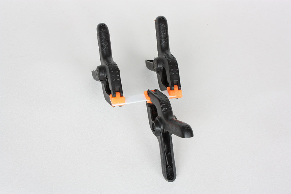
Anyway, here we are now. I've decided the best filler for styrene wherever possible is...styrene! I cut sections of 1.6 mm styrene rod and placed them into the ejector pin marks. Tamiya Extra Thin was then run in, the plastic given a few seconds to soften, then pressed down with the butt end of a cocktail stick so that the molten plastic filled the mark.
I'll let this harden overnight then sand down with my David Union tool.
Cheers, Kirby