Steve Eagle Posted June 19, 2023 Share Posted June 19, 2023 All that green on the inside makes me think of “ the Green Mile”- Long walk from front to back. HB252 1 Link to comment Share on other sites More sharing options...
ChuckD Posted June 21, 2023 Author Share Posted June 21, 2023 Agreed. All that monotone green is a bit boring. I've started blocking in small bits and it's helping. I think some good detail painting and weathering will really be the key to making it all more visually interesting. ... Before I close it up nothing will be seen of it. Steve Eagle 1 Link to comment Share on other sites More sharing options...
TimW Posted June 23, 2023 Share Posted June 23, 2023 Don't forget plenty of silver drybrushing and grime... Tim W Link to comment Share on other sites More sharing options...
TankBuster Posted June 24, 2023 Share Posted June 24, 2023 14 hours ago, TimW said: Don't forget plenty of silver drybrushing and grime... Tim W Less is more with the drybrushing or you end up with the frosted look. Cheers. TimW 1 Link to comment Share on other sites More sharing options...
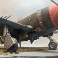
ChuckD Posted June 28, 2023 Author Share Posted June 28, 2023 Hi, guys. It's been a little bit, but I've been far from idle. I just tend not to get too bogged down with photos of the various phases of interior painting... priming, base coating, detail, chipping, decals, filters, washes, dirt, etc. So, here we go. The Quickboost B-17 .50 barrel set came in. As you can see, the difference between the kit barrel and the QB barrel are night and day. Borrowing from @leoasman, I thinned the back of the IP, drilled out the dial faces, put the decals on a cardstock backing piece and glued that to the back of the IP. Worked like a champ and I'm glad they posted their methods. Anyway, for spraying the flat coat, I masked the IP with silly putty. The decals are a mix of kit decals and some from an Aeroscale generic cockpit placard set that I had. The yellow framing around the six pack is just super thin tamiya tape strips. The final product after pulling the putty. A few shots of the interior at the end of the finish work. The MRP zinc chromate is a bit bright yellow, so I toned it down with oil washes, enamels, and speckling. In photos the speckling looks overdone, but in 1:1 scale, they're much more subtle and go a long way towards breaking up walls of color. Again, Aeroscale decals. Chipping was done with the sponge technique using Vallejo Model Air silver. The cockpit roughed in. The nose wheel well with lots of dirt and mud splashes. The bomb bay deconstructed (and sans the actual bomb racks). More Aeroscale decals. Before this gets buttoned up, I'll add a gunsight reflector from clear film. Ye olde bombe racks. I went with natural finish for a little visual interest. The upper deck above the bomb bay. Nothing aft of the three small radios is remotely visible, so I didn't do much painting here. If you wanted to add a bunch of details, it's a pretty awesome blank canvas. The luggage rack. Nose gear and rear ammo can. The QB barrel installed (some more detail painting was done later as shown). The MGs are the weakest parts of the kit. If you're really concerned about the soft detail here, the Gaspatch M2 is going to be the way to go. Ye olde bombes for said racks. Assembling the nose well. The bomb bay is assembled. Very little of the sides walls can be seen. Dry fitting the turret while the glue on the bulkheads dries. The cockpit assembled. One last shot before it's closed up and lost forever. A quick shot to give an idea of how much is going to be visible once the canopy is put in place. Short answer is: Not much. The turret. Bomb bay after assembly. Not much can be seen here. Fortunately, the part that can be seen is the QB barrel. A milestone! The fuse went together pretty well. The little section between the nose and bomb bay is still the gap that requires the most physical strength to shore up. A lot of liquid superglue was the remedy for getting it to stick together. The plate that forms the base of the vertical stab fits reasonably well, though there's a gap on the left root. Nothing too bad though. The shot below is dry fit and the cemented gap is much smaller. Next it's building the nose and tail feathers, then on to the engines. More to come! Dpgsbody55, Greg W, Learstang and 31 others 34 Link to comment Share on other sites More sharing options...
LSP_Kevin Posted June 28, 2023 Share Posted June 28, 2023 Excellent work, Chuck. She's a dirty bird! Are you talking about Aeroscale or airscale? Kev Link to comment Share on other sites More sharing options...
leoasman Posted June 28, 2023 Share Posted June 28, 2023 (edited) Really looks amazing! Does the turret have to go in prior to putting the fuselage sides together, or can you drop it in later. I haven’t got that far. Edited June 28, 2023 by leoasman ChuckD 1 Link to comment Share on other sites More sharing options...
MikeMaben Posted June 28, 2023 Share Posted June 28, 2023 Some nice work Chuck ChuckD 1 Link to comment Share on other sites More sharing options...
ChuckD Posted June 28, 2023 Author Share Posted June 28, 2023 6 hours ago, LSP_Kevin said: Excellent work, Chuck. She's a dirty bird! Are you talking about Aeroscale or airscale? Kev Eeeh, I don't know, I'll have to look. Could be the latter. Short term memory and all. LSP_Kevin 1 Link to comment Share on other sites More sharing options...
Troy Molitor Posted June 28, 2023 Share Posted June 28, 2023 Loving your build Chuck. ChuckD 1 Link to comment Share on other sites More sharing options...
ChuckD Posted June 28, 2023 Author Share Posted June 28, 2023 (edited) 11 hours ago, leoasman said: Really looks amazing! Does the turret have to go in prior to putting the fuselage sides together, or can you drop it in later. I haven’t got that far. It drops in, so you can remove it at your leisure. I think it's snug enough that it's not just going to fall out, but it can be removed without too much hassle. I had a few minutes before work this morning, so I poked around at a few things. The tail pieces went together pretty well. They are large and sturdy with solid connection points. The connection points allow for complete freedom in positioning the control surfaces. I didn't photograph it (would've needed 3 hands), but dry fitting the stabs to the tail looks like there will be some tweaking used to get things to fit without gaps. I'm going to leave the tail off until I get wings and landing gear under the model because I don't want the tail surfaces to be load bearing while the unfinished kit is sitting on its side. To emphasize my point above, when the kit is sitting on its side, the wing roots force the fuse to roll towards its belly, so the nose gear takes up a side load. I might move on to the wings after this (as opposed to the engines as per instructions) just to get some leveling factor and to get the load off the nose gear. I had just a few minutes to dink around with the fit of the nose. Having done the B-25 and B-17 from HKM, this was a concern for me as neither of those kits had great fitting noses. I'm very impressed with the tentative fit here on the A-20 kit with the caveat that none of the internals are in place yet. Here you can see the fit with nothing more than the weight of the two nose fuse halves holding it in place. This tiny gap here will likely shore up very nicely with cement. Edited June 28, 2023 by ChuckD scvrobeson, Greg W, patricksparks and 19 others 22 Link to comment Share on other sites More sharing options...
Pete Fleischmann Posted June 28, 2023 Share Posted June 28, 2023 Looks outstanding Chuck! What particularly jumps out at me are the bare metal items- I love the way you’ve finished these- very convincing. Love it best P ChuckD 1 Link to comment Share on other sites More sharing options...
Learstang Posted June 28, 2023 Share Posted June 28, 2023 Excellent work on the A-20! I won't say you make it look easy, but you certainly make it look doable. I've already test-fitted the empty nose to the empty fuselage and was very impressed by the fit. That, as with your test fit, is with nothing glued in the nose (or the fuselage for that matter), but it's still promising. I was musing over whether to attach the nose halves to the fuselage halves or glue the finished nose onto the finished fuselage. I'm now definitely leaning towards the latter. Regards, Jason Link to comment Share on other sites More sharing options...
Gazzas Posted June 29, 2023 Share Posted June 29, 2023 I really... really like the way you weather the interior parts. You add so much depth. Link to comment Share on other sites More sharing options...
ChuckD Posted June 29, 2023 Author Share Posted June 29, 2023 I've been a busy boy today. First let's bang away at the nose. If it weren't for this build thread, I probably would've left a lot of this stuff out. However, I want to share my follies with you so that you can learn from my inevitable mistakes. Anyway, the tl;dr of this is, the nose fits great and the internals don't affect the fit to the fuselage - that all too critical join is very very nice even with all the internals in place. Blah blah. Less talk; more pics. First little issue - the instructions illustrate this little tab (K13) that sticks into the open hatch panel upside down. If installed per instructions, it interferes with the two ammo cans that straddle it. Flip it over as shown in the photo below. With that corrected, the right nose section goes together nicely. The steps are repeated on the left side. The only difference here is that the two notches in the side piece that ride over the ribs on the fuselage floor need to be widened. That small flare out on the ribs interferes with the side piece and prevents the latter from sitting flush with the curve of the fuse floor. I like that the ammo cans are split along the width of the can, not the long axis. I believe HKM adopted this non traditional method so that the modeler would not have to fix a seam line that would be visible when the side hatch is left open. More pictures below show what I mean better than I can explain it in words. Here I replaced the .50 barrels with the QB set. The kit parts were just as disappointing as the other .50 barrels. I glued the two bulkheads into the left fuse half to provide stability as I was trying to mount the .50s and it worked well. I was able to dry fit the nose (after drilling out the holes to accommodate the QB barrels) to help establish the proper alignment of the gun barrels. The lower .50s were mounted in much the same way. A shot of what's going on in the nose. There is tremendous room for detailing here and a fair number of the hatches can be left open if you so desire. I don't, ergo I will not be painting or leaving hatches open. The nose halves and nosecone are glued together. The fit was wonderful and HKM deserves the highest praise here. Once the sprue gates are cleaned up, all major parts fit together wonderfully and will require only the smallest amount of smoothing to get rid of any imperfections from the cementing process. Here you can see the seams in the ammo cans that I was mentioning earlier. Even if you opt to leave every hatch open, these seams will not be seen. Aaaand here's where I can level a complaint. The fit of the six panels on the nose is not super great. Relative to wonderful engineering that led to the flawless fit of all that junk in the nose, these panels were a let down. Ignoring the fact that some of the liquid cement wicked under my finger and marred the surface (I'll fix that later), no amount of finagling could get any of these panels to fit without some sort of filler being required. I think HKM intended for the modeler to leave them all open, leaving some of us to deal with a sub-par fit. Okay, okay, they're not awful and I have definitely seen worse, but I was a bit let down by them after the rest of the nose fit so well. A little filler and a some light sanding ought to be enough to hide them under a coat of OD green. If I were doing NMF, that'd be a different story. But I digress. There's a forward bulkhead that goes into the fuselage that I wasn't aware of while painting. I wish I had been because, as you can see, it's quite obvious as it forms the forward wall of the nose wheel well. It's dry fit here and required just a little bit of sanding to fit the assembled fuselage, so it'll go to the paint booth in the next day or two. Here's the nose taped together. Again, the fit is wonderful. I haven't test fit the cheek panels yet, nor added the PE (presumably) armor strips that go next to them, so we'll see how those go. But, again, even with all the crap crammed into the nose, it fits the fuselage nearly flawlessly. The aforementioned PE armor plating. On to the left main. Contrary to the chintziness of the nose gear (thank you Douglas Aircraft Corporation), the main gear is a sturdy mess of triangles, braces, and stiffeners, oak board, concrete, titanium, and a kitchen sink. Assembly is straight forward except for the little doodad that looks like it's got a pulley on it (see arrow). The instructions are not clear as to where it goes and there's a small slot on the bottom of the main swing axle into which it fits. I originally fit it into a slot on the other side of the axle and it was just not right, thus the messed up glue bit. Live & learn. I also left the door actuator rod off and will install it once I have a gear door to attach it to. It attaches to the little Y yoke towards the bottom left. After the landing gear comes the nacelle. It was very painless to assemble with the exception of this one little piece. Again, the instructions could be better here as the angle they show for the little brass divider on the intake doesn't really help you understand the placement. It's a lot harder than I thought it would be to find a photograph of the inner side of the engine nacelle, but I finally located one on some russian site somewhere. I'll probably be ransomewared by morning, but whatevs. It's just my modeling PC. Anyway, the brass part should more or less divide the intake and should not stand out forward of the lip of the intake itself. Oh, I also assembled the tires too. If I do this kit again (and I may, it's quite fun), I will deffo spring for the Eduard wheel set with the crosshatch treads. The kit set is workable but underwhelming. I then moved onto the left wing (the engines will come later). The assembly here was without issue and the fit was magnificent. The leading edge seams will clean up with minimal effort and the same can be said for the 3 control surfaces. The carb intake is glued on. It doesn't have any keying to line it up, but there's a panel under it that matches its outline, so it's hard to mess up. It fit perfectly. With a Tamiya cement bottle doing a stand in for the right wing, I locked the left wing in and set her up. She's definitely starting to look the part! I was a little hesitant to test fit the wing. I did that with the B-25 and it never came out again. Happily, the left wing on the A-20 has been more compliant to my efforts and can easily slip on and off while still locking in tightly when in the proper place. Very little, if any, gap on the upper wing root. Lower wing root is very nice too. I was able to finagle it a little bit after this picture to get it to fit better towards the leading edge. So, I'm optimistic that the wings will be a very easy install. A shot showing the full length of the wing. The nacelles fit nicely as well. There may be a small gap on the upper surface where the nacelle meets the wing behind the carb scoop. I can't tell yet if that's just an artifact of the taping job or whether or not it'll require filler. Either way, it's not too bad and shouldn't be a problem. I wanted a visual reference as to the size of the A-20G vs the B-25J. As you can see the latter is quite a bit larger on the shelf. Thanks for following along. I suspect I should be able to get the right wing and gear done tomorrow, then its off to paint some more, then to tackle the engines. I'm hoping my Pacific Profiles book comes soon - my wife ordered it for me for father's day and it's still not here. It's now due in "by Thursday" but we'll see. Failing that, I've found a few neat Pacific birds that I could probably emulate. I enjoy trying to recreate historical photos, so I want to find an A-20 on the ground, but most of them were photographed in the air. Anyway, I'll settle on a paint scheme before too long. I promise. patricksparks, MikeMaben, Shoggz and 17 others 20 Link to comment Share on other sites More sharing options...
Recommended Posts
Create an account or sign in to comment
You need to be a member in order to leave a comment
Create an account
Sign up for a new account in our community. It's easy!
Register a new accountSign in
Already have an account? Sign in here.
Sign In Now