geedubelyer Posted January 24, 2016 Share Posted January 24, 2016 The engine face turned out beautifully Rich. Very convincing. Good job. Cheers. allthumbs 1 Link to comment Share on other sites More sharing options...
richdlc Posted January 24, 2016 Share Posted January 24, 2016 really excellent work , clean and sharp allthumbs 1 Link to comment Share on other sites More sharing options...
allthumbs Posted January 26, 2016 Author Share Posted January 26, 2016 (edited) Thanks everyone for your interest in this (long-running) project as well as your kind comments...most appreciated . Work continues, in "inside-out" fashion, on the Intruder air intakes which, as it turns out, contain several interesting external features as well, like air data probes, antennae, boarding ladders, emergency canopy jettison handles and a number of servicing panels, including one for the single point refueling receptacle, located low on the starboard side. Originally, the refueling port was concealed behind a rectangular access door, as seen in this diagram from the 1969 NATOPS manual (item 10)... By the early 1970s, the design was simplified. The hatch was removed and in its place was installed a panel with a circular opening, permanently exposing the receptacle. Here's a picture from an EA-6A walk-around by Patrick O'Donnell, Marine Corps aviator, expert modeler, and all around good guy ... The EA-6B Prowler design is very similar, but not identical - the opening moved to a more accessible 7 o'clock position and reinforced with a raised flange (vs. the flush-cut opening on the Intruder models)... Good close-up pictures of the refuel adapter itself are hard to find. However, the design is very standardized across fleet types, including civilian aircraft. So I made due with photographs and measures taken from one of our birds at work... As you can see, the diameter is slightly more than the length of a standard credit card. Using appropriately sized brass tubing, along with some plastic bits, I fashioned my own in 1/32 scale... This photo shows the completed fueling receptacle, painted and weathered (just a bit, as I think these things are kept pretty clean), alongside the starboard air intake, into which was cut the circular opening. The saddle shaped part on the left installs from behind and will serve as as a mount for the adapter... And speaking of saddles, it's good to be "back in the saddle" as they say. After several months of uninterrupted work on this project, progress inexplicably came to a sudden halt last autumn. I can't explain it. And I've stopped trying to analyze it. . For whatever reason, the motivation is back - happily, as I've got a lot of work (enjoyment ) ahead of me, not to mention commitments to a business partner for the conversion kit! Thanks for tuning in. More to come soon. Rich Edited May 30, 2020 by allthumbs Harold, Greg W, Starfighter and 9 others 12 Link to comment Share on other sites More sharing options...
LSP_Kevin Posted January 26, 2016 Share Posted January 26, 2016 Superb work, Rich! Back in style, I'd say. Kev allthumbs 1 Link to comment Share on other sites More sharing options...
ClumsyDude Posted January 26, 2016 Share Posted January 26, 2016 Wow, Rich, great scratch building. Love that refuelling adapter. Jim allthumbs 1 Link to comment Share on other sites More sharing options...
Youngtiger1 Posted January 26, 2016 Share Posted January 26, 2016 (edited) Dude, totally awesome as usual. You are raising the bar way up there with sharp and clean skills. As Zohan puts it....silky smooth...and you know, you don't mess with Zohan on that Edited January 26, 2016 by Youngtiger1 allthumbs 1 Link to comment Share on other sites More sharing options...
Loic Posted January 26, 2016 Share Posted January 26, 2016 allthumbs 1 Link to comment Share on other sites More sharing options...
wardog Posted January 27, 2016 Share Posted January 27, 2016 Awesome work on the adapter. Attention to detail and crispness of your work is second to none. Patiently waiting for more. Elmo allthumbs 1 Link to comment Share on other sites More sharing options...
Guest Posted January 27, 2016 Share Posted January 27, 2016 Good stuff!!....Harv Link to comment Share on other sites More sharing options...
Starfighter Posted February 3, 2016 Share Posted February 3, 2016 Incredible Rich, to say the least! allthumbs 1 Link to comment Share on other sites More sharing options...
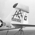
allthumbs Posted June 23, 2016 Author Share Posted June 23, 2016 (edited) "One step forward, two steps back." Almost exactly one year ago, on these pages, I proudly displayed pictures of my completed EA-6A tail. Though not obvious from the photographs, there were some nagging alignment and symmetry issues with the large "football" fairing that sits prominently atop the vertical stabilizer, particularly apparent when studied from head on. While slight, the flaws nevertheless bothered me. Adding to my anxiety was the realization that there was no easy fix. My only other option was to start all over again. And that is what I did...but not before stepping away for a while to collect my wits. Wits collected (along with a new set of fuselage halves - an eBay seller was offering individual "parts trees" for the kit at reasonable prices), version 2.0 finally began to take shape. The "clean slate" approach allowed me to incorporate additional details too, as, during the break, I was fortunate enough to acquire some close up photographs of the Electric Intruder's tail - thanks Patrick, Steve, and Rick! Comparing old against new, you'll be hard pressed to see any difference, at least in the accompanying photos. But examined close-up in person, with a critical eye, the distinctions are apparent. I'm very pleased with the results...not to mention relieved! I can forge ahead now with a clean conscience More of the new tail... I put to test some new techniques as well. The new documentation photos revealed some access panels and raised fairings located along the blended area that unites the vertical stab and the tail radome. Not trusting my scribe across a complex curve made of epoxy putty, I prepared a couple of appliqués. The first was an adhesive-backed Mylar film called Monokote Trim http://www.monokote.com/trim.html . It can be cleanly cut to shape and, once applied, adheres very well to smooth surfaces. I used it for the more prominent wedge shaped fairings near the rudder. For the rectangular panels, I used spare decal material, which offers just the right amount of relief. That's provided you avoid high quality (read thin) products like Microscale's or Cartograf's...I knew I'd find a use for those thick Hasegawa transfers! Neither material responded well to my usual practice of depicting fastener detail with a needle and small drills. So instead, HGW's positive rivets - so called because they're slightly raised above the surface - were applied to the panels http://hgwmodels.cz/en/content/17-positive-rivets I like this product line. A wide assortment of lines and shapes is offered in three different scales (1/72, 1/48 and 1/32). Compared to the competition, they're finer and more consistent with regard to shape and spacing (almost too fine; be careful when laying down paint over them). And perhaps best of all, HGW rivets are devoid of any excess carrier film. However, an accompanying curse sits beside these blessings. And that lies in the application process, which is long-drawn-out...a patience tester for sure! The raised surface detail on the aft face of the radome is .005 inch sheet plastic, cut to shape, set into position, and bonded with Tamiya Extra Thin Cement (applied sparingly). Again, HGW rivets were set in place, one-by-one, according to references. Patrick O'Donnell photo Steve Belanger photo Notice too that the rudder has been brought up to Electric Intruder standards: the interference plate along with two static discharger mounts, the latter sprouting up on EA-6A airframes around the mid 1970s. The fairing at the base of the rudder (near the nav light socket) was reshaped to achieve a more accurate rectangular cross section at the end - out of the box, it's too rounded. Finally, the rudder leading edge upper hinge point was repositioned a few scale inches down to match references. Thanks everybody for your indulgence and kind support. It's very much appreciated! Rich Edited May 29, 2020 by allthumbs NavyF4s, johncrow, A-10LOADER and 4 others 7 Link to comment Share on other sites More sharing options...
LSP_Kevin Posted June 23, 2016 Share Posted June 23, 2016 This is just so good. Kev allthumbs 1 Link to comment Share on other sites More sharing options...
allthumbs Posted June 23, 2016 Author Share Posted June 23, 2016 (edited) Incidentals... The EA-6A, like its Prowler cousin, had a prominent raised dorsal fairing located amidships. It housed an ADF receiver antenna. On his EA-6B conversion, Ben (Starfighter) cleverly adapted the similarly shaped Doppler antenna fairing found on the belly of most Intruder marks, but only on select Prowlers. As I needed to preserve this feature on my build, I went about things differently, carving out a new antenna using two pieces of sheet plastic: .080 inch stock for the main body, .015 inch card for the perimeter flange. The latter was first heated up over a stove and then "drape-formed" over the upper fuselage, creating the proper curvature. A number 87 micro twist drill was used to simulate the fasteners that ring the enclosure. By the way, those small vents that flank the antenna are in need of some work. Due to mold parting restrictions, Trumpeter had to distort their shape somewhat. Injection molding limitations also preclude a hollowed-out effect. Roy Sutherland to the rescue! Browsing his Barracuda Studios site, I came across this obscure offering...http://barracudacals.com/proddetail.php?prod=BR32155 Although labeled a Luftwaffe product, it's obviously meant for the Trumpeter 1/32 Intruder - note the delicate, thinly molded vents in the last photograph - they even include some spares! I'm not sure what that other stuff is for...maybe the abandoned Grumman A-6G "Gustav" project. Seriously, the set is affordable, easily adapted, and sure to enhance the scale appearance of this big jet (or even a Messershmitt I suppose). Bye for now, Rich Edited May 29, 2020 by allthumbs A-10LOADER, F`s are my favs, Vandy 1 VX 4 and 6 others 9 Link to comment Share on other sites More sharing options...
petrov27 Posted June 23, 2016 Share Posted June 23, 2016 Really looking fantastic and great find with that Intruder upgrade set for the little scoops!! allthumbs 1 Link to comment Share on other sites More sharing options...
alain11 Posted June 23, 2016 Share Posted June 23, 2016 Hi I just browsed your WIP , i am stunned by your skill , , .....a piece of art Alain airscale and allthumbs 2 Link to comment Share on other sites More sharing options...
Recommended Posts
Create an account or sign in to comment
You need to be a member in order to leave a comment
Create an account
Sign up for a new account in our community. It's easy!
Register a new accountSign in
Already have an account? Sign in here.
Sign In Now