ChuckD Posted July 1, 2023 Author Share Posted July 1, 2023 Yeah, this one is interesting. I'm really hoping someone more knowledgeable than I comes out of the woodwork to shed some light on the situation. Here's where I wish I was a whiz with CAD, Blender, and a 3D printer. If you get the design right, these cowls would be a cinch to produce out of a 3d printer. Link to comment Share on other sites More sharing options...
ChuckD Posted July 2, 2023 Author Share Posted July 2, 2023 ****. CRAZY IVAN5, leoasman, TAG and 10 others 2 11 Link to comment Share on other sites More sharing options...
Learstang Posted July 2, 2023 Share Posted July 2, 2023 Hmmm, someone needs to come out with some brass landing gear for this kit. Reparable, but still a bummer. Regards, Jason Link to comment Share on other sites More sharing options...
ChuckD Posted July 2, 2023 Author Share Posted July 2, 2023 Yes, indeed. A set of brass would be great. This is fixable and I'll recover, but it's frustrating. The kicker is, I didn't even realize I did it until I happened to see it. Soooo, it couldn't have been from a hard impact, which lends to the argument that the nose gear is a weak spot of the kit (as a result of the actual a/c design). I'll leave the repairs until I have the wings attached and can then put it on my jig. I was right earlier on though: Leave the tail pieces - particularly the horizontal stabs - off until you get the wings on. I put the tail surfaces on yesterday and I'd bet dollars to donuts that the setting the fuse with attached horizontal stabs down is what put a side load on the nose gear and snapped it loose. Without wings, the fuse won't sit on a jig well either. I hope that makes sense. scvrobeson, leoasman, HB252 and 2 others 5 Link to comment Share on other sites More sharing options...
ChuckD Posted July 2, 2023 Author Share Posted July 2, 2023 Damn the torpedoes broken nose gear! Full speed ahead! I've been making good headway over the past couple days and have not been as diligent as I should have been with posting pictures. So, let's play a little catch up. Using Magic Sculpt epoxy putty, I shored up the gaps in the nose panels a couple days ago and it turned out splendidly. You can see that I had also started the first round of sanding the seams. They were pretty minimal, all things considered. I'm going to try to highlight the areas I had to fill and sand so others can keep a sharp eye out for gaps. The trailing edge of the rudder had some gaps that I couldn't close while cementing, so it got filled and sanded. I might do a little more shaping to give it better taper towards the rear. A couple spots on the leading edge of the wing, but very very minimal. This tail plate was what gave me the most troubles. All 4 corners had to have some kind of filling. Though not terrible, they are in an awkward spot with tough geometry to work around. I highly recommend leaving off all 3 stabilizers until you're done sanding (AND HAVE THE DUMB WINGS ON SO YOU DON'T SNAP THE DUMB NOSE WHEEL OFF). A couple spots on the nose needed a little filler. I primarily used liquid sprue to fill these gaps, then Mr Surfacer 500 for any subsequent clean up. This gap panel at the bottom between the rear hatch and bomb bay was problematic and I saw it coming when I glued it together. No amount of finagling would get the two halves to sit evenly here, so there was a step between the two pieces. I sanded it as close as I could get, then filled with liquid sprue. Okay, so here's where I started to get myself in trouble. Again leave the tail stabilizers off until you've got the wings on. Reason being that without the wings, you can't really set the fuselage down without putting a heavy side load on the nose gear once the tail feathers are on. The fuse is off balance enough that it won't sit on a jig well and when you try to set it down on a flat surface, the leverage of the horizontal stabilizers combined with the weights in the model's nose, imparts a significant torque effect on the fuselage... and guess what little chintzy part is left to carry the load? See my previous post for a hint. So yeah, here's where we put the tail on. This is the bottom of the vertical stab. I had to scrape quite a bit of material off the bottom flange of the stab as well as the locating tab itself to get the stab to sit in its groove without rocking back and forth. I think the locating tab is just too long to fit the corresponding groove in the upper tail plate. So, without removing some material, it'll teeter totter back and forth with neither side achieving a good fit. However, this was an easy fix. Scrape a bit and you're good to go. The horizontal stabs benefitted from a little bit of sanding at their mating surfaces and with a combo of liquid super glue and some cement, they went on well. There was just a tiny gap that I had to fill with more epoxy putty. Mind the dihedral in the horizontal stabs. The A-20 had a pretty significant dihedral in the tail planes. The gaps... The tail more or less together. The control surfaces are still dry fit at this point. RIGHT HERE IS WHERE THE DUMB NOSE GEAR BROKE OFF. But, with copious amounts of liquid super glue, we recovered. And, as a bonus, we made other progress too. I spent the day painting the remaining interior parts like that pesky bulkhead that sits between the nose and fuse that forms the front of the nose wheel well. In doing so, that allowed me to install the nose. The final fit was pretty good. That little seam I had to sand on the forward bit of the fuse came back to bite me a bit as there is now a small - almost imperceptible - step between the nose and the forward fuselage. You can juuuuust make it out here. To be fair, I took great pains to try to show it off for you, but it's so small I think a quick swipe or two with a sanding stick on the nose ought to level things out just fine. The rest of the nose fit is just phenomenal. Great stuff. I'm really impressed. As mentioned, most of my day was spent painting and weathering the remaining interior bits which included the nacelles, landing gear, and gear doors. Again, I didn't photograph the progress, but rather just the more or less finished product. Here are the main gear and nacelle rooves on the bottom side of the wings. I added a couple brake lines (to be cut to length later) to spice things up a bit. It is surprisingly hard to find a good shot of landing gear plumbing on this thing. Here are the nacelles. You could lose your mind cleaning up ejector pins if you want, but they will be invisible anyway, so I didn't bother. Likewise, the nacelles are a wonderful canvas for super detailing if you see fit. I see that Eduard is planning a gear bay set, so I'm sure there'll be a lot of great details added here. Again, I dirtied these up pretty well as I figure the a/c in the SW Pacific weren't kept clean, and as anyone whose been in the gear well behind a radial engine can tell you... those areas get grubby. Once the nacelles are installed, this is just about the most you'll ever see - and this view isn't obscured by the landing gear mechanism. I glued the nacelles together then to the wing. All went together very nicely with a combo of liquid super glue and cement. The outer nacelle pieces on both sides needed to be pressed outward from inside then tacked in place with liquid super glue to mate to the channel wing channel without a gap. Again, the view once fully assembled. The other ancillary bits that I painted today: gear doors, inner flaps, bomb bay doors and associated mechanisms. Happily, once on her feet with the wings tacked in place, the nose gear holds up. I think HKM probably put just the bare minimum weight in the nose to guarantee the tail didn't fall, so hopefully the load on the rinky-dink nose gear isn't too much in the end. I did not put a sinker in the nose cone assembly as I had previously intimated. And with that, we're caught up. I have the day off tomorrow, so I'll try to make some good progress on the engines and exhausts. Once everything save for antennas and such is installed in their respective bits, I'll glue the wings to the fuselage. I know some people prefer to paint the wings separately, but if at all possible, I prefer to paint the whole thing together. The B-25 didn't leave me a choice and it turned out okay, so I'm confident I can paint it all as one without too much trouble. patricksparks, Citadelgrad, LSP_Ray and 28 others 31 Link to comment Share on other sites More sharing options...
LSP_Kevin Posted July 3, 2023 Share Posted July 3, 2023 Terrific update, Chuck! Bummer about the nose gear, but everything else is looking great! Kev ChuckD 1 Link to comment Share on other sites More sharing options...
Dpgsbody55 Posted July 3, 2023 Share Posted July 3, 2023 Great pictures detailing your progress, Chuck. Very neat work. Love your dirtied up parts too. That tones down the yellow ZC a lot and gives the model some life. Hope you can fix the nose gear too. Cheers, Michael ChuckD 1 Link to comment Share on other sites More sharing options...
HB252 Posted July 3, 2023 Share Posted July 3, 2023 I love the nose shape, great job !!!! I thank you for your explanación and time you put in It!!! ChuckD 1 Link to comment Share on other sites More sharing options...
ChuckD Posted July 4, 2023 Author Share Posted July 4, 2023 Some more progress today. The cheek gun panels went on just fine. A little filler and some light sanding to remove my fingerprints and it'll be just fine. Here you can see the gap between the nacelle and the wing root. A little filler was needed here too just to clean it up. The nacelle after the first round of sanding. I used a little Mr Surfacer 500 to fill a hole here and there on the nacelle joins. In all though, they went together flawlessly, especially considering how complex the join between the nacelle, the upper wing surface, and trailing edge pieces. These were later smoothed out scribed and re-riveted, so the wings are now done. After annealing the two PE armor panels, I installed them. Annealing is a must here - the PE is very stiff. I first tacked it in place with a little dab of CA glue. Then I took a glue looper and liquid CA glue and went around the piece tacking down each side until it was set all the way around. It conformed nicely to the curve of the fuselage and is nice and secure. Just go slowly here and anneal, anneal, anneal. I also finally got around to putting the gunsight and glass on. Looks pretty good if I do say so myself. Beyond that, I spent time getting the engines painted and prepped. I'll post pics when they're done, hopefully tomorrow. Keepin' on truckin'. Alex, TankBuster, Dennis7423 and 24 others 27 Link to comment Share on other sites More sharing options...
Learstang Posted July 4, 2023 Share Posted July 4, 2023 Chuck, you're not doing a good job of persuading me not to start on my kit. Regards, Jason Uncarina 1 Link to comment Share on other sites More sharing options...
LSP_Kevin Posted July 4, 2023 Share Posted July 4, 2023 Excellent progress, Chuck. You're really rocketing through this one! Kev Link to comment Share on other sites More sharing options...
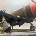
ChuckD Posted July 4, 2023 Author Share Posted July 4, 2023 (edited) 13 hours ago, Learstang said: Chuck, you're not doing a good job of persuading me not to start on my kit. Regards, Jason 11 hours ago, LSP_Kevin said: Excellent progress, Chuck. You're really rocketing through this one! Kev Thanks, Kev! We didn't have much going on for the July 4th holiday weekend, so I've been afforded the opportunity to spend a good chunk of time at the bench. I'm back to work tomorrow, so I suspect the build will slow down pretty heavily after that. I've also decided that I'm going to wait for the Eduard wheel set to finish this off. So, I'll get as far as I can, but an RFI will wait till then. So, let's talk cowlings for a little bit. I tried really hard to keep the cowl assemblies separate and tracked as, out of aaaaaaaalll the itty bitty bits that make up the engines assemblies, the cowl and flap ring are the only handed parts. Yet alas, I ran into an issue. Let's explore. Here you can see the assembly for the left engine... ... and here the right. In either case, the cowl and flap ring (whether you choose the flaps-open or flaps-closed option) are individual components on the single M sprue. All other engine components are from the duplicated L sprue. The flap rings are keyed to their individual cowling, so it is (thankfully) impossible to swap rings between them. Once assembled, the engine is sandwiched between the cowl and flap ring parts, then the whole cowl-engine-ring sandwich gets installed on the firewall part L21 (which is a duplicate and the same on both sides as shown below). Note, that L21 is keyed to the stub on the nacelle by a flat spot at the 6 o'clock position. Likewise, the stub on L21 itself is keyed with a similar 6 o'clock flatspot. Left... Right. Sprue details from the instructions. What's interesting is that the nacelles themselves are, of course, handed, so L21 fits differently on both sides. Notice the slightly different rotational orientation of the cutouts at the top of L21 and the key on L21's stub. In both cases, there is a small shoulder cut on L21 that provides the real positive positional lock on the underside of the wing where it meets the nacelle. Once you have the grooves on L21 snugged into that corner, is pops perfectly flush against the face of the nacelle. So why does all that matter? Because the wrong cowl will just barely fit on the correct wing and will throw off the geometry of the engine assembly noticeably. Here you can see the proper alignment of the engine without the cowl. Note that we can (and did) draw a straight line from the carb intake on the wing to the bottom cylinder which passes through the keying notch in the baffle, rear upper cylinder, governor mount pad, prop shaft, and lower cylinder. Continuing that theme... With the correct cowl in place, that same straight line will pass through the split at the bottom of the cowling itself. The mating faces of the wing, cowling, and nacelles will also be nice and snug. Now, see what happens when we try to put the wrong cowl on the wing. You can see that the cowl is rotated a few degrees counter clockwise. Beyond the obvious problem of aesthetics, the real issue is that it you can force the wrong cowl to fit with the engine in place. Because of the keying of the engine baffle to the inside of the cowling, the engine will also end up rotated a few degrees counter clockwise with the cylinders and prop governor pad out of vertical alignment. But, with enough tape and some super glue, I could absolutely see myself not realizing my mistake until too late. As I said earlier - I really tried to keep the two cowlings separate so that I was sure I had the left cowl with the left wing and vice versa. But, when I went to test fit the engine & cowl on the left side with what I thought was the left cowl, I got the fit in the last photo. If I hadn't noticed that the cylinders were subtly out of alignment, I may have proceeded to make things permanent. The problems are compounded by the fact that with how the whole sandwich fits together, it's difficult to test fit without having at least the engine permanently together. I have no way of knowing now whether or not the parts are mis-numbered in the instructions or whether I, despite my best efforts, managed to swap them during the painting process. Occam's Razor says the latter is the most likely, but please use due care while putting your engines and cowlings together. If you have to use more force than you would expect, you probably have the wrong cowl. Edited July 4, 2023 by ChuckD AlexM, Learstang, LSP_Kevin and 19 others 22 Link to comment Share on other sites More sharing options...
geedubelyer Posted July 4, 2023 Share Posted July 4, 2023 Chuck, you're doing a fine job of wrestling this kit into shape, well done. Now, I wouldn't know a Havoc if it ran over my foot but, what's everyones take on the surface texture? It appears quite prominent and unusually uniform all over the surface of the airframe. Was the real aircraft like this? ChuckD 1 Link to comment Share on other sites More sharing options...
AlexM Posted July 4, 2023 Share Posted July 4, 2023 Very interesting to follow. My kit just arrived today ChuckD and Learstang 2 Link to comment Share on other sites More sharing options...
LSP_Ray Posted July 4, 2023 Share Posted July 4, 2023 Thanks for the heads up on the cowls, Chuck! ChuckD and CRAZY IVAN5 2 Link to comment Share on other sites More sharing options...
Recommended Posts
Create an account or sign in to comment
You need to be a member in order to leave a comment
Create an account
Sign up for a new account in our community. It's easy!
Register a new accountSign in
Already have an account? Sign in here.
Sign In Now