
Dpgsbody55
-
Posts
2,303 -
Joined
-
Last visited
-
Days Won
2
Content Type
Profiles
Forums
Events
Everything posted by Dpgsbody55
-
New YouTube video interviewing the ICM MD about how that company is going and future plans. ICM Interview Cheers, Michael
-
I hadn't realised these were original colour pictures. Great shots. It's so good to have colour pictures of the plane you're modelling and these are fascinating too. So many details to see. Your rendition is turning out very close to these shots. Cheers, Michael
-
My best result in terms of models built in a year, since I've been retired, is five. As were LSP's as that's all I build. The first three were from the Eastern Front GB in 2020 1) SH Yak-3 2) KH P-39Q 3) ICM I-16 Type 17 (on skis) 4) Trumpeter P-47D Razorback 5) Trumpeter P-40B I may have built more models in a year, but that was probably when I was in my teens and we won't talk about how many years ago that was.... Cheers, Michael
-
Looking good. Not much left to go. I think your model compares well to the picture. Maybe a little more dust and dirt, if you're so inclined? I'm also looking at the rear faces of the prop. The degree of worn paint is not nearly so great as might be imagined, and very subtle. I'm wondering how much of the appearance of wear here is due to the colourisation of this period picture. Perhaps there's a lesson here for me too. Cheers, Michael
-
In addition to other's comments, there's a forum here for non LSP work. I'd be very surprised if you presented your armour projects there and not get some good feedback. It might also give others some food for thought too. Cheers, Michael
-

Clostermann's LO-D by Airfix Spitfire Mk.IX
Dpgsbody55 replied to Dpgsbody55's topic in Operation Overlord
Thanks Kevin. Cheers, Michael- 57 replies
-
- 1
-

-
- eduard brassin
- eduard
- (and 2 more)
-
As well as some changes to the cockpit layout too. The electrical systems on Mk.VIII's were quite distinct from earlier marques, which were basically just variations on the Mk.I. Cheers, Michael
-
Clostermann's LO-D by Airfix Spitfire Mk.IX
Dpgsbody55 replied to Dpgsbody55's topic in Operation Overlord
Not so much a model update, as a personal one. I had surgery on my wrist on Wednesday so now I have a plate and pins and expect to set off airport scanners. If anyone needs a weather forecast now, just ask me . It's now likely that I'm going to be away from the modelling bench for quite a while, which is very annoying, so it's unlikely I'll finish this by the deadline. Cheers, Michael- 57 replies
-
- 1
-

-
- eduard brassin
- eduard
- (and 2 more)
-
*COMPLETED* Trumpeter 1:32 P-47 Thunderbolt ‘Bubble-top’
Dpgsbody55 replied to Shoggz's topic in Operation Overlord
Very nice. Looks every inch like a P-47. Cheers, Michael -
Three??? Hmmmm.... Spitfire Hurricane Macchi C-202 FW-190 Piper Aerostar 600 Cheers, Michael PS. Sorry. Got a bit carried away after realising that five was right out, so I went back to three.
-
Happy birthday, Mike, and many more to come, I hope. Cheers, Michael
-
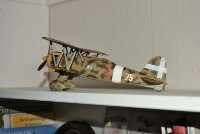
SPAD XIII C.1, Frank Luke Jr. (RODEN 1/32)
Dpgsbody55 replied to sillymodeler's topic in Ready for Inspection
Nice model. Very well finished and a good display too. Cheers, Michael -
An excellent build, and the electrical animations add a lot to it as well. Great paint job too. Cheers, Michael
-
An excellent build. Cheers, Michael
-
There has been some good suggestions here for the next Airfix release. Here's a few of mine, in no particular order. 1) P-40. It would have to be a later one as the B/C models have been done. But how about a Merlin powered P-40?? 2) P-51B. We're all crying out for one. Bear in mind that Airfix have said they won't de-do an old release, so no likelyhood of a new Spitfire Mk.I, Stuka, P-51D, BF-109E etc. So I'd suggest a P-51 highback model would sell as we can't be the only people wanting a good model of such a plane. 3) Griffon powered Spitfire. Surely a no brainer?? Mk.XIV's look best to me, without the bloated tails of the later ones, and they saw service in WW2 Plenty of choice with markings and would make a good basis for a resin or 3D print conversion set to make it a later version for them as want such a thing. 4) FW-190D. The A has been done in 1/24. Does anyone not want a long nose Dora done as well as the Spitfire IX?? 5) P-47 Razorback. I know there's another of these in 1/24, but it doesn't hold a candle to Airfix's excellent Spitfire IX. Personally, I always prefer the looks of the original design, be it Spitfire, P-51 or P-47. They just look right. And I think the P-47 has been unjustly overshadowed by the P-51 too. A very worthy plane warranting the Airfix treatment. An alternative suggestion would be the last variant, the P-47N which was surely the best escort fighter of the Pacific theatre. 6) Nakajima Ki-84. A very worthy choice for something from the Pacific theatre and a good match for Airfix's Hellcat. Possibly Japan's best from that era?? I'd buy it. 7) Hawker Tempest. Another outside chance, given their also excellent Typhoon, but a good candidate. Or they could do a Centaurus powered model. 8) Bristol Beaufighter. Another one many here would like to see, and also another plane from WW2 which model companies have unjustly ignored. It's a bit of an outside chance, and I'm not sure how their Mossie sold, but I'd still like to see one in LSP. I could go on, but I see these as the best choice for Airfix to make another successful LSP. Notice I haven't included a 109F or G. I think there's enough good LSP's there to make that choice less viable for Airfix, though I do not include any of Trumpeter's offerings in that thought. Cheers, Michael
-
I have the original release version of this. So the question is do I buy this one too, considering it;s better markings??? Hmmmm...... Cheers, Michael
-
I'm disappointed that Airfix have made no announcement about another version of their Spitfire Mk.IX. At very least, you'd think they'd do a Mk.VIII given the way the fuselage is molded. Cheers, Michael
-
I'm not sure if these are new old stock or simply new stock, but Hannants and Kitlinx are advertising KH P-39's again. So if this is on your wish list, take a look at these sites. Cheer Michael
-
Good to hear he's on the mend. I hope he's up and about very soon. Cheers, Michael
-
Clostermann's LO-D by Airfix Spitfire Mk.IX
Dpgsbody55 replied to Dpgsbody55's topic in Operation Overlord
Very true. It is plastered and I see the ortho surgeon next week so hoping it doesn't need surgery. This is the first time I've ever been plastered, at least in the sense of a cast. The other type of plastered has happened on occasion but we won't go into that right now..... . Can't wait to get back to normal. I've always valued my independence. Cheers, Michael- 57 replies
-
- 2
-
-
- eduard brassin
- eduard
- (and 2 more)
-
I hope there will be an AM decal set available in Russian front winter camo. That would be my pick for my Z-M kit. Cheers Michael
-
Clostermann's LO-D by Airfix Spitfire Mk.IX
Dpgsbody55 replied to Dpgsbody55's topic in Operation Overlord
Thank you both. My own stupidity caused this, so I just have to grin and bear it. I've always enjoyed cycling and my current bike is a pedal assist e-bike which is great to ride and keeps me fit too, which my cardiologist appreciates as much as I do. The thing I'm having the most difficulty with is writing left handed (some say I can't write with my right hand either - they're correct there ) and trying to wash my left armpit with my left hand. Give that a try. I dare you. Cheers Michael- 57 replies
-
- 1
-

-
- eduard brassin
- eduard
- (and 2 more)
-
This looks totally brilliant. Wonderful work. Cheers Michael
-
Yep. Done stuff like that. At least it looks good now. Cheers Michael
-
Clostermann's LO-D by Airfix Spitfire Mk.IX
Dpgsbody55 replied to Dpgsbody55's topic in Operation Overlord
More bad news. Turns out the wrist is broken and not just a simple break but one bone broken and another dislodged. So now I'm plastered and not in the enjoyable way . Oh goodie..... At least my mind is occupied trying to find ways to do basic stuff with my non dominant hand. Shaving is slow but at least my jugular is still intact. Cheers, Michael- 57 replies
-
- 3
-
-
- eduard brassin
- eduard
- (and 2 more)
