
Madmax
-
Posts
508 -
Joined
-
Last visited
-
Days Won
4
Content Type
Profiles
Forums
Events
Posts posted by Madmax
-
-
21 hours ago, jenshb said:
If I should hazard a guess, I'd say the 6-3 wing has the sharper leading edge to allow a smooth transition to the existing aerofoil after extending the leading edge.
Good craftmanship and research here - thanks for posting.
Thanks Jens.
I agree with you - the deeper leading edge of the 6-3 extension necessitated a different airfoil section. This had a notable impact on the handling of the aircraft (particularly the initial hard wing).
Here is a good reference for Sabre fans: https://finescale.com/~/media/files/pdf/online-extras/sabre/sabretable.pdf
In the table I found the answer I was looking for, at least for a Korea F-30.

So, the SAAF's Sabres had a late A-5 wing with new inner hardpoints! The important thing for me is that it had the same slat tracks as the F-86A. This is what they look like...

This means that the slat tracks I ordered are wrong.

That was bugging me - a lot, so I ordered some new ones. Pricey hobby!


It's not often one gets to see this leading edge without the slat attached. I was surprised at how sharp it is, certainly compared to the truncated representation in the kit.


I risked sanding it to the same fine edge, but there just wasn't enough plastic to pull it off. I then resorted to shoving styrene into the compromised sections - not very tidy but it has saved the project from the bin for now...

It looks a bit better after initial shaping.

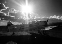
Enough of that. I was wondering about the incredible complexity of the various modification states of North American Aviation products in the 1950's, and the staff required just to do the admin! Maybe this is how it was?

I messed with the photo - just having some fun.

- scvrobeson, BLACK MAMBA, JolleyRoger and 12 others
-
 12
12
-
 1
1
-
 2
2
-
At first, I thought the slat issue was quite simple.
Based on the majority of slat track photographs I have "mined" from the internet, I sent off this simplified design to to a local etching company.


I was lulled into believing that all slats were created equal thanks to evidence like this... (there are eight "actuators" btw)

and here is a part catalogue drawing to support what I thought was the standard part.

In essence, the slat track is thicker above the slot than below. Then I started to see other evidence.

Thicker below. Sure, this is a VERY early F-86, but it got me thinking.
This photo in the Thompson book piqued my suspicion. An F-86 F crash reveals a slat track that is thicker below the slot, more like the early wing. The tracks are slightly bent from the impact, but the inspection panels on the leading edge confirm the orientation.

So what is going on down here in the rabbit hole?
Jennings Heilig created this guide to the basic differences between Sabre wings, and many of you with an interest in the subject would have seen it already. It is excellent for pointing out the basic differences, but he warned on the forum (that it was originally posted on), that the subject deserves a book. Agreed.

Here are some more differences that I started to notice. The slots in the leading edge are different, and this one is like the Korea Sabres.

And this one is not.

The shape of the leading edge of the early Sabres also caught my eye - they are quite rounded, blunt if you like.

And this one is sharper...

This may be more difficult to prove in court, but I think I can see it...

I'll get to the point in the next episode.
Sean
-

Yup, that's where I have been - probably still am.
The Hasegawa wing isn't ideally suited for conversion to a narrow-chord slatted one, but it will have to do. I really don't like the way the slat tracks are represented in the kit, so this was one of my first considerations. Based on a multitude of photos of slat tracks, and the structure of the model wing - I came up with this idea (this is just a styrene prototype of what I would like done in etched brass).

This requires a roller of sorts inside the leading edge, and here is my solution.

With that in place, it was time to join the wing halves. You will notice that there is no structure inside the wing to maintain the airfoil apart from the leading and trailing edge joins. Because of this I opted to first join the wings, and then perform the next major surgery, which is to remove the 6-3 leading edge extension. The slat track openings on the kit wings run very far back, and I was concerned that due to the lack of structure the leading edges would not survive the surgery. At this point I added styrene fillers to the overstated slat recesses in the hopes of propping up an otherwise wobbly affair.
Now to remove the 6-3 extension...

Job done, but to my surprise, the kits upper and lower separation lines for the leading edge don't match up. I was hoping to sand the opened leading edge joins flat, and emulate the attachment of a non-extended leading edge as it was on the real Sabre. No such luck.


Pity, but in order to retain the airfoil shape, I joined the leading edges as cut. Then came the job of scribing the detail on top of the wing. although I followed a lot of Hasegawa's detail on the fuselage, it would be wise to look carefully at the wings.

Understandably, a kit from the 1970's was predicated on drawings from that era. Many of the panels on a wing are based on the line from which it is squared on. On a tapered swept wing it is hard to guess what the datum is, so detailed photographs (or the real thing) are a must!

This one, is anyones guess...

I'll leave you with that thought for now, and on the next instalment, explain what has happened in the rabbit hole so far.
Cheers,
Sean
-
-
Ooh, that is looking fantastic Malcolm! I really like the improvements to the gear legs and the canopy framing - very cleverly done.
-
-
Wonderful progress Malcolm - the hard edge camouflage looks fantastic!
-
As per usual, the drawings one bases measurements on need to be accurate, and good F-86 blueprints are very difficult to find. Based on a cross section of those I have found, and photographs, this is the piece of the elevator that should be removed to get the proportion correct.

Here is the final product (on the right), compared to the original and the Kinetic part.

The elevator was separated from the stab and its leading edge rounded along with scalloping the stab trailing edge. The rudder was built up a bit in order to give it a rounded leading edge too.

With the tail feathers taken care of, it was time to get stuck into the wings. Maybe its the age of the kit, or the size of the lower wing moulding - but man is it ever warped! It looks like a poppadum fresh out of the microwave oven.

All of the longer wing parts are warped, so I popped them into hot water and proceeded to bend them into a flatter state. The slats didn't like the treatment much, and one broke up into its constituent parts.
 There is quite a bit of work planned for these distinctive features!

The wings of the SAAF's F-86F-30's were (with one exception) the early slatted narrow-chord wing. This means that I will have to remove the "6-3" extension from the leading edge, as well as the 12" tip extension of the F-40 wing.

I am planning to remove the leading edge at the point where it is attached on the real aircraft via a spanwise toothed piano-hinge. The panel line indicated in the oval should move to the tip join.

Removing the "6-3" extension means the whole shape of the wing-fuselage join at the leading edge changes too. This presents a real head scratching problem.

Since real Sabres look like this with their wings removed, I figured it might be the way to go with the model too. It is a fascinating wing join - looks like the wing centre section is bolted onto a box like structure in the fuselage. No visible spar? (Photo borrowed from the AMARC Experience website)

Now that the centre section is removed, it is a bit easier to work with. First the wheel wells can be detailed (the etch is from the Eduard set, since the kit doesn't include the brake housing at all).

There was a bas relief attempt at detail for the wing portion of the well, which was scraped off and some styrene added instead. Seems as if I only ever do wheel wells...

Cheers,
Sean
- Chris Wimmer, GROWLER 96, MDuv and 15 others
-
18
-
Glad it brought back some memories Derek. I imagine you are no stranger to Martin Baker and Irvin, which in turn (and thanks to the work of our survival equipment professionals) saved a couple of my friend's lives. I can still recall the feeling of strapping on a Martin Baker seat as if it were yesterday, even though it has now been more than 20 years since I last had the privilege!
Nick, the painting of walls is done for now, but I have been away from the bench again - installing flooring...

Thanks Tom and Violator, the scratch building of detail is one of my favourite aspects of the hobby.
The seat looks pretty uncomfortable to me too Iain. Luckily the Sabre didn't have great endurance - and I recently read that it was fairly commonplace for guys to dead-stick back into their base airfields!

Never too many Sabres Tim, and I see another has just arrived on the scene...
-
Enjoy the build Tim!
I don't know of any 1:32 decals for a SAAF Sabre in Korea, and I'm keen to see what you come up with. There are decals from AIMS for F-51 Mustangs in Korea, but that will only work for the fuselage as they are all 36inch roundels, and you need 30 inch roundels for the wings. I haven't worked out a solution for mine yet, except to say that I hope Nick has his Silhouette cutter fine tuned to cut small Springbuck stencils...
-
Rivets, shiny Alclad and decals on top - not for the faint hearted! You have pulled off a hell of a balancing act here Chuck, well done.

-
-
-
It was my turn to cook dinner last night, so I rushed my update and forgot to show you the lovely Aires ejection seat all painted up.

I based the colours pretty much on this photo from Warren Thompson's "F-86 Sabre Fighter Bomber Units Over Korea" (Osprey) which is a must-have resource.

Working on the seat reminded me of a cartoon that the inimitable Bob Stevens created for the AIR FORCE magazine many years ago. One of my favourites!

- TAG, D.B. Andrus, JolleyRoger and 9 others
-
7
-
5
-
1 hour ago, MikeMaben said:
Some of my parts used to do that too ...

Looking good Sean, do you know if 'all' Korean war 86s had that IP ?
Thanks for the pic

You don't miss a thing Mike - very funny!
Good question regarding the IP's. I would venture that 'most' Korean war Sabres had that IP, since they were mainly E's and F's from 1952 onwards. That being said however, the 4th Fighter Interceptor Group were flying F-86A's in Korea since late 1950, and the A's IP didn't have the mega compass in the middle (the artificial horizon was there).
The E-10 and later models had the big compass (actually a DI).

This is an actual SAAF F-30 cockpit:

Maybe there are some Sabre boffins out there who can add to this? The internet discussions on the subject (mainly for the digital simulation crowd) are a bit inconclusive.
-
Thanks very much to one and all, your enthusiasm is much appreciated!
A weird thing happens between dry-fitting and the application of glue - I swear the parts swell up in anticipation. Here you can see how tight the fit of the resin cockpit actually is. I had to file a notch in the top of the intake trunking so that the cockpit would fit without filing away any more of the sidewalls. The difference between the kit cockpit and the Aires resin is quite noticeable, and it is obvious the extra depth has to be absorbed somewhere!


With the seat rails now attached, I was able to measure and manufacture the headrest. It attaches to the aft bulkhead and not the seat due to the way the parts are moulded.

The Korea Sabres had a unique feature to the instrument panel - a HUGE radio magnetic compass slap bang in the middle, and a rather emaciated artificial horizon next to it on the right. Nick and I has a discussion about this recently, and agreed that many a Sabre accident investigation of the time would have noted that the pilot was totally spacially disoriented, however headed in the correct direction when he hit the ground.

I know I said at the beginning that I might have to live with some inaccuracies, but, you know... Malcolm (Mistral) will be chuckling about this. I used some Airscale instrument bezels to help correct the size of the compass, as well as add some depth to a couple of the existing etched bezels. 0.5mm styrene rod for lights and knobs. The compass face is a bit undersized for the bezel now, but the effect is still an overall improvement for me and my OCD. Notice how much deeper the Aires IP is (top to bottom), compared to the kit part.

Then finally, some paint! The Korea cockpits are plain black, and as such need a bit of weathering, decals and detail to bring them to life. Hairspray chipping over silver and zinc chromate for the basics, some Airscale and spares-box decals and a bit of chalk dust brushed over all.


With the cockpit painted, I could finally join the fuselage halves. Most of it joined up well, but you will notice a fairly large styrene shim in the upper nose join. This is actually quite an important widening of the nose profile, and means that the windscreen actually fits (It is too wide for the fuselage otherwise).

The Sabre's horizontal stab and elevators are critical to the look of the aircraft. The proportions are key, and something about the kit parts seems wrong. This is how the relationship of leading edge, central structure and elevator should look.

This is how the Hasegawa parts (in light grey), and Kinetic (in dark grey) look. Not great, but I think the Hasegawa parts will be easily fixed.

Stay tuned,
Sean
-
Your build sequence for the Mirage is very clever Malcom - it really does eliminate some horrendous joins that result from following the kit sequence. One of those strange mysteries of life, since the parts don't change
What is your trick for leaving the main gear legs unattached at this point, and is the nose wheel leg glued in?
-
-
-
Hey Iain, as I recall, Jimmy builds models and I have heard you build great models. Time to show us some!
The Sabre is slowly progressing, however, the further I delve into this build, the more I realise why there are only two 1:32 scale Sabre kits out there.
The nose wheel-well is detailed about as much as I would like.


The actual leg is complete, and I drilled out the openings in the wheel hub so that one can see through them. There are two types of hubs in the kit, the other with lots of "spokes", but this is the one most prevalent in photographs of SAAF Sabres in Korea.


The intake trunking was joined as designed in the kit, being side by side, and then cut into a top and bottom halves as per the actual join in the aircraft. I filled the top intake section at the lip so that it is about the size of the intake ring. There are lots of ejector pin marks in the exhaust sections that were drilled out and filled with styrene rod rather than putty.

Here you can just make out the actual seam line of the trunking.

The intake halves are painted while still separate, and then joined to get this effect...


It is a little crude, but I hope the Tamiya engineers are taking note. The Kinetic kit employs this top and bottom method for the intake and I think it is the way to go.
The rest of the parts of the engine were painted so that I can get a measure of how it all fits into the fuselage.

The first thing was to get the intake attached to the fuselage via the nose wheel-well and the intake lip. I have done this in the left hand side of the fuselage only, and keep dry fitting the other half to check that is stays symmetrical. Quite a bit of filling and sanding still had to be done at the lip join, which is one of the more difficult engineering challenges for the designers of a new Sabre kit. I'm very keen to see how the soon to be released Airfix 1:48 Canadair Sabre goes together, particularly all the tubes inside the fuselage!

All the time that the intake trunking was being positioned, I was checking to see if the Aires resin cockpit would fit.
Happily I can report that it does! ")
While the fitting was going on, I noticed that there are virtually no cockpit sills on this kit, or the Kinetic one for that matter. Eduard supply some in their interior etched parts, that I modified to achieve a fairly slim sill that the canopy rails and air-conditioning tubing could be attached to (that is a lead weight glued on top of the intake trunking btw).

I am very pleased that the Aires cockpit actually fits, albeit with a lot of trimming and sanding!

Before getting to the mega alignment challenge, I added some depth to the "heat shield" in the exhaust, but also complicated things a bit for myself. Not sure it was worth the effort.

Alignment of all the internal organs is the true challenge in shrinking this beautiful aircraft. I haven't got it right yet, but here you can see what all has to be attached in harmony to achieve a true flow of air from one end of the model to the other. I think it will be better if separated into an intake and exhaust module Mr Tamiya!

Plumb Bob please nurse...
Sean
- blackbetty, Derek B, Scotsman and 15 others
-
18
-
Maru, Dit is baie gaaf van jou om 'n boodskap in Afrikaans te skryf. Ek waardeer jou ondersteuning!
Malcolm, good of you to voice your support too...
Baie Dankie,
Sean

-
-
-
Thanks Alan!
Iain, an ATC from Hoedspruit, now living in Christchurch - what a thing!
Thanks for looking in on the Sabre. It really is fun trying to work out the engineering of the aircraft based on photographs. One day I suppose our SAAF Museum will open up again, and then I will be able see just how the parts actually fit together.
The last ACM Camp I took part in was at FAHS, and the only thing we ever seemed to announce to the tower was "Bingo" fuel. As you might gather, I didn't fly F1's!
WingNut Wings Albatros D.V - Ltn Wolf, Jasta 5.
in Ready for Inspection
Posted
Beautifully done Whitey. It is a real treat to look at, and for some reason, makes me feel like drinking beer!