
Madmax
-
Posts
578 -
Joined
-
Last visited
-
Days Won
4
Content Type
Profiles
Forums
Events
Posts posted by Madmax
-
-
Excellent work Malcolm, and two great saves already - the ailerons and the cockpit colour!

-
With the rib tape situation under control, it was time to get some of the other parts smoothed out and primed. The removable canopy panel took a fair amount of filling and sanding to get a smooth transition into the clear part, and the spats were a real challenge to shape. Lots of filling and sanding required there too. Notice the clever bit of kit engineering inside the cowling for the engine to fit inside a near scale thickness of the actual sheet metal. One will obviously have to glue the two halves over the engine once it is in place!

The next move was to design some masks in order to spray the scalloped shapes. The kit plans have some very useful 3-view drawings, but I still tweaked these a bit based on the reference photos I have available. Now poor Nick @Cheetah11 has to translate my shoddy drawings into 'silhouette language' in order to cut the masks! I think I'll have to buy Black Forest cake for my next visit to his place...


And now I have started to spray an undercoat of white on the areas that will become a more pleasant yellow than the kit plastic. Even over light grey primer, it takes many light coats of white paint to make an opaque undercoat. Some patience required!

The kit prop looked too much like a constant speed prop, with a clearly defined hub. I have tried to make it look more like the original prop which was quite possibly a single piece of aluminium milled into shape.

Here you can see the shape of the actual Curtiss prop, and an interesting discovery. The early 'Z' had three louvre vents (per side) behind the engine...

Whereas by race-day there were only two per side.

There are more interesting little tweaks that I'll point out as the model progresses.
Until then,
Cheers!
Sean
-
On 5/9/2025 at 10:59 PM, Mal_Belford said:
Hey, doesnt matter, as im here waiting for the next move, even better, it takes the time it needs to take, nothing else.
/Mal
Here comes the next move Mal...
On 5/10/2025 at 1:05 PM, malc said:Wow, I did not expect you to actually follow my advice!!!!😁
Looking good.
Malc.
How could I not????
 On 5/11/2025 at 9:51 AM, DerekB said:
Those rib-tapes look excellent Sean, looks like a few more of us will be copying Malc's method. I plan to try this on the tail-feathers of my Wirraway. Plus I have a bunch of these Williams Brother's kits in my stash...
Good plan Derek! You're lucky to have some of the Williams Bros kits stashed - I wish I had bought more when they were still readily available.
-
So, armed with Malc's tip and a look at what @tomprobert did with his Sterling, I set about cutting up some Tamiya tape and carefully masking off the wing ribs.

It is actually a very effective way of getting the spacing and thickness right, one just has to be patient...


I decanted some normal Tamiya grey primer into the airbrush (ie. not the fine primer), and voila - rib tapes!

They came out a bit too prominent at first, so I gently sanded them back with a sanding sponge. There is some variety in the effect now, which I quite enjoy. You can see the final result under some fine grey primer:

It is a relief not to have to look at that yellow styrene for a change. Thanks again for the tip Malc!
Cheers,
Sean
-
On 4/9/2025 at 4:47 PM, malc said:
Great update!
What I like about following your build is thinking, 'yes, thats exactly what I would have done'!
Armchair satisfaction......!
One tip I would like to pass on - I always find that when simulating ribs/rib tapes with streched sprue, at the sanding stage a few always come loose at the ends and dissapear.
Masking the wing (minus the rib tapes) then applying a couple of layers of heavy primer results in much better representation of the tapes - after a bit of gentle sanding to round off the edges of the primer following removal of the masking tape. @tomprobert is using this method on his remarkable vacform Short Stirling build.
Looking forward to how you do the red lines!
Perhaps use one of these and make a template guide to follow?
Malc.
An extremely useful tip for the rib tapes Malc! Read on, you'll see...
On 4/9/2025 at 11:03 PM, LSP_Kevin said:Impressive work, Sean!
Kev
Thanks for the encouragement Kev!
On 4/9/2025 at 11:07 PM, Mal_Belford said:Yes, agree with kev.
Cant wait for the next step on this build.
Here it comes Mal. Takes a while as I'm often away.
On 4/16/2025 at 10:21 PM, Hubert Boillot said:Fantastic work on the Z.
FYI, Kelik, a brand from Reskit, produces a 3D-decal of rib tapes in 1/32 … I am not sure that you will get the scalloping effect at the extremities …
Hubert
I couldn't find the Kelik tapes, but saw some from HGW and Quinta that I may well use on a Gladiator in time to come. Thanks Hubert!
-
Excellent work on the wheel wells Leon. The kit is a bit of a fight, but keep going!

-
Clever move not to tackle the chord and the slats Malcolm! I'm afraid that, regardless, you still have quite a job on your hands. The nice thing about this kit is that you will know every panel line and rivet on an F-86 by the time you're done...
- BLACK MAMBA and KiwiZac
-
 2
2
-
-
This is superb Hubert! You could even possibly sneak the 'Little Prince' into the scene... just kidding, but it evokes that kind of mood. Wow.
-
With the fuselage halves joined, I could finally get down to modernising the surface of the kit. Considering it is a 1979 kit, raised detail comes as no surprise, but at least it appears to be pretty accurate. I have used the raised lines as the guides for scribing and reshaping as indicated in these photos.


You may recall that the air intake scoop wouldn't align, but there is enough material to carve and sand it into one unit. It just needed one tiny piece of styrene to neaten-up the lip

Then I ran into a tricky issue. The upper surfaces of the wings have a nasty sink mark at about 1/3 chord length, and there is no way to fill it or sand it without losing the rib-stitching detail. The one place where raised detail really is useful!
 I elected to sand the wing, rather than struggle with putty, and then glue stretched sprue into scribed lines where the ribs are. The snag is that the final effect just isn't convincing, the spacing wasn't perfect and the lines weren't totally parallel. In other words, it looked pretty rubbish. I sanded it back and have tried again, but much less prominent and fading away towards the tips. Maybe it won't be seen at all, but I can't sand the wings any more, since they already resemble ironing boards. Best left alone, rather than jeopardise the whole build...


This is how the stitching actually looks. Pretty prominent...

Another tricky aspect of the build is how to put back the removable canopy panel should one want it posed like a whole aircraft. I have seen a build where the panel has been vac-formed, but the fit of such parts is normally slightly off (in my experience) and I don't have any decent equipment for the job at any rate. So, I have made do with what is in the kit and just modified it a bit. It will do for some long distance photographs, but no detail shots of the removed panel!
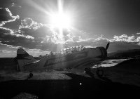
(B&W shots to give your eyes a break from the horrendous yellow plastic)


At this point, I have come to understand why so many Gee Bee models don't actually get completed.

Ah well, not keen to give up yet, I stuck the wings on before they end up looking like wafer biscuits. If nothing else, at least it looks really cool at this point! Bob Hall was clearly a creative guy as far as aircraft design goes.

As you can see, it is not the easiest of builds. I have had to use some two part putty to fix the wing join, but to keep the spirits up - I made a proper metal tail-skid and used thin styrene to represent the rubber 'boot' the Granville Bros put on the real thing. Little things sometimes spark joy.

Most of the kit parts need some attention to improve them, like the struts for the horizontal stab that are rods on the sprue, but should be flattened oval in cross section. Then I would also suggest using your own axles to put the wheels in after the spats have been painted. Enough bellyaching from me - it's still great fun. What I'm really looking forward to, however, is to see how to paint a 0.1 mm red pinstripe between the distinctive black and yellow scalloped shapes that make this paint job pop. That's bound to make the flat wings seem like child's play!

Cheers,
Sean
- Dpgsbody55, malc, LSP_Kevin and 16 others
-
 19
19
-
On 3/29/2025 at 4:32 PM, Uncarina said:
I love how you are bringing this to life Sean, and great save with that cockpit! The Rocketeer is kind of creeping me out with that praying mantis eye, but aside from that it’s a great cover illustration. I can also easily envision the Gee Bee somewhere in the Tintin series.
Cheers, Tom
Thanks Tom, glad you're enjoying it! The project kinda brings itself to life I must say, being such an iconic little plane. I know exactly what you mean about the Tintin series, it would fit right in...
On 3/29/2025 at 11:05 PM, Mal_Belford said:Oooh Yes, love every step on this build....
This chubby aircraft comin alive, just love it.
Your enthusiasm is infectious Mal!
On 3/30/2025 at 8:45 AM, malc said:Nice! Thanks to your mention of the Eicher-Kimball rep, I found the video of the first flight which was interesting to see.
Malc
Thanks Malc, it's a great video. Delmar Benjamin clearly was the man for the job!
- Mal_Belford and Uncarina
-
2
-
Despite how worried Trumpeter made these chopper-jocks look, I'd say they're in good hands! Excellent work Patrick.
-
-
-
-
So, every time I add something to a model, it affects something else. Simple universal stuff really, but one forgets.
It's the inside-out engineering that inevitably catches me, since I'm always trying to add detail to the inside of a model, and only then closing it up. If you get the sizing wrong, the outside bits don't close properly, and instead of rethinking the whole affair, the natural reaction is just to squeeze a bit.
The delicate little cage of 0.88mm styrene rod buckled silently inside the fuselage, as I hit the joining halves with extra thin cement and clamped it all together. I was rather pleased with myself that it all basically mated, except for the intake scoop under the chin. I then left everything alone, to let it cure properly. Once I'd freed the tiny yellow egg from its shackles, I peered inside the cockpit to marvel at the detail, but that wasn't what was staring back at me. All those lovely straight and parallel stringers looked like cooked spaghetti, as they'd buckled along with the cockpit tub. I didn't take a photo - too painful.

I won't bore you with the rest. It's kinda fixed now, but not quite as neat as it once was. On a more upbeat note, I subsequently discovered that you can get a paintbrush into a much smaller areas than you'd ever imagined!

The stringers are now stuck to the insides of the fuselage btw, with superglue - that's why the paintbrush had to do some contortionist tricks!
And also why the seat has been broken off its rails.

Since the seat was out, I thought it would be nice to check the ergonomics of the cockpit. 'Biggles' looks as if he'd easily reach the rudder pedals, stick, and even the throttle. He'll just have to bend his left arm a bit!

Apparently he was pissing himself with laughter at how wonky the stringers look.

@malc, here's one for you. I took the Matra launcher decals off the IP and replaced them with something more appropriate:

Since I was discussing the cockpit frame, here is something interesting I discovered during my research. The original frame had a cross member just short of the IP, like this...

Which the Eicher-Kimball replica faithfully reproduced. (This image was off an R/C Model forum, apparently taken by Kevin Kimball)

But due to differences in fuselage size and design, the Turner replica doesn't have a cross member there at all.

I thought I should finish off with a further reference to the Art Deco thing. The Rocketeer , on which the movie was based, was originally a cartoon character created by writer/artist Dave Stevens in the 1980's. Stevens himself was clearly looking to include Art Deco influences in the cartoon, and often portrayed the Gee Bee Z. His artwork is fantastic, and well worth looking up. If not for the Gee Bee, then certainly for his portrayal of Bettie Page.

Cheers!
Sean
- Uncarina, Oldbaldguy, coogrfan and 14 others
-
17
-
On 3/27/2025 at 1:15 PM, Mal_Belford said:
WoW.....and WoW.
Unusal aircraft comin alive here, and love that engine and cocpit and the rest, weathering looks fantastic,
Like that its unusal and other colors than military, you got my attention.
/Mal
Hi Mal, unusual it certainly is. Most pleased to have your attention!
On 3/27/2025 at 2:14 PM, Out2gtcha said:Lovely work! The extra effort taken on the cockpit tub is very evident.
Thanks Brian, always good to have you check in. The extra effort very nearly derailed this model! Read on...
On 3/27/2025 at 7:57 PM, John B said:Awesome project. Following this one. Thanks for sharing all the great references.
JB
Cool, thanks JB. More references coming up.
On 3/27/2025 at 8:50 PM, Troy Molitor said:Looking great Sean.

Thanks Troy!
On 3/27/2025 at 9:31 PM, malc said:Blimmin marvelous, I like your sketches of the parts you want to make.
Not normally a fan of scale deviations, but the art deco instrument panel is great!
Malc.
I'm pleased that you'll overlook the deviation this time Malc.
On 3/28/2025 at 1:06 AM, Oldbaldguy said:Crimanittly but that is one short-coupled fuselage! Having the tailwheel that close to my butt would give me the willies even if the airplane was locked up in a hangar.
Hey OBG, it gives me the willies too! I've seen the videos of Delmar Benjamin and Kermit Weeks flying the Eicher-Kimball replica, and there is a lot of rudder happening on the ground!
4 hours ago, Dpgsbody55 said:Your cockpit work is a massive improvement on the kit offering. Great work.
Cheers,
Michael
Thanks Michael. It was great fun to manufacture the new bits and pieces, but I will be measuring more carefully in future!
1 hour ago, Grunticus said:Fantastic work Sean! This is the first time I see a build thread of this kit, very nice. Great to see what a skilled modeller can do with such ancient base material.
Hey Leon, I've noticed that of the few builds of this kit out there, many don't get completed. Let's see what happens!
-
On 3/15/2025 at 8:06 PM, malc said:
That there interior is looking really impressive.
M.
Thanks Malc, here's some more...
There is something very Art Deco about the 'Zee', which I chose to play up a bit in the cockpit. Not terribly accurate, but having some fun with it!
The IP is cut from a sheet of aluminium, holes drilled as round as possible and then trimmed with Airscale instrument bezels to neaten it all up. The combination of aluminium and brass is quite fetching, I thought, so I didn't paint the bezels black (which they were). The instrument faces came from the original kit decal and a Hasegawa P-47. A bit hodgepodge, but does the trick.

See, Art Deco!
The magneto selector got sliced off a Löök Hawk IP that I'd purchased hoping to use the instruments (that was a big fail btw). If you read carefully you'll notice the two cubbyhole door labels got poached from a Matra launcher decal. I only saw that in the photo afterwards...

The trim wheel is from a 1:48 Me 109 etch upgrade, and the throttle is cut from the same aluminium sheet as the IP. The knobs are just blobs of epoxy. There are only two levers, since the original aircraft had a fixed pitch prop, unlike the modern replicas that have variable-pitch constant-speed jobs.

At least the Löök set had a harness in it that I could tart up my interpretation of the seat with. So easy using coloured steel belts!

Just realised I missed a step. The seat was made from the kit part, but more of an attempt at a very basic lightweight sheet-metal over a frame kind-of-thing. 'Biggles' had to try it out, and he was thoroughly unimpressed, even though he was laughing uncontrolledly at the time.

Here are the major parts that now make up the cockpit tub. Takes a bit of work, but much nicer than the old kit parts.

This is what it looks like assembled. Once the fuselage halves are closed one will wonder (as we always do) why spend so much time on a cockpit that can't be seen? No point in trying to answer that.


Cheers!
Sean
- Furie, SwissFighters, Out2gtcha and 22 others
-
25
-
-
I'm afraid my wheel-well fetish appears to be is contagious!
I like the 'clean slate' approach, Leon. Now the trick is to decide just how much you want to add. The Daco book is going to probably turn you into a hydraulic engineer by the time you decide you've shoved enough piping into the model. Good luck...
-
-
Well done Marcin, sometimes it's the recognition from unexpected people that makes it all worthwhile! Your hand-crafted figures are absolutely fantastic...

-
-
Nailed it Malcolm! It's got that 1950's colour-photo feel to it, and I can almost hear the guys singing 'Izika Zumba'.

1/32 GRUMMAN J2F-5 'DUCK' FLEET AIR PHOTO UNIT ATLANTIC | LUKGRAPH
in Works in Progress
Posted
Fantastic - looking forward to this build Lukasz! Piotr's artwork for the box top is absolutely brilliant...