

Kahunaminor
-
Posts
936 -
Joined
-
Last visited
-
Days Won
2
Content Type
Profiles
Forums
Events
Posts posted by Kahunaminor
-
-
-
6 hours ago, Thunnus said:
Since the RB Productions set doesn't include a Revi 16 gun sight, I'll have to dig into my spares box to see if I can drum something up.
Stunning work as always John.
May I suggest Quickboost’s 1/32 Revi 16B? From memory they come in a pack of three and should be available fairly easily.
Scalemates description here:https://www.scalemates.com/kits/quickboost-qb-32-006-gunsights-revi-16b-3x--211725
If you cannot find a set readily, drop me a line and I will mail you a set.
Regards.
Kent
-
Mate,
Frontline in NSW is also fairly well stocked IIRC.
Regards
PS What are you after? I may have it in stock at Kentco.......
-
-
-
You are a machine Sophie!
Great work in cracking time, well worth the visit!
Regards,
Kent
- curiouslysophie and Scale32
-
 2
2
-
-
Sophie,
ZM also do a book of concept notes which is quite good.
Regards,
-
A great result Sophie,
You have a build list of excellent kits in line. It will be a pleasure to watch these come to fruition.
Regards,
-
Many thanks,
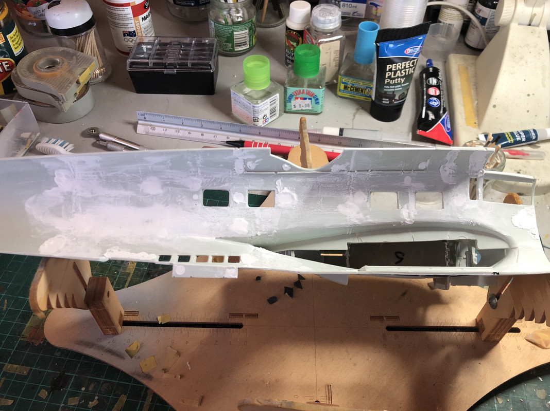
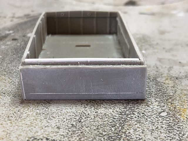
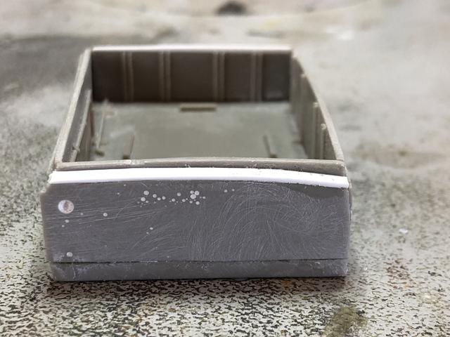
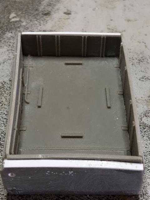
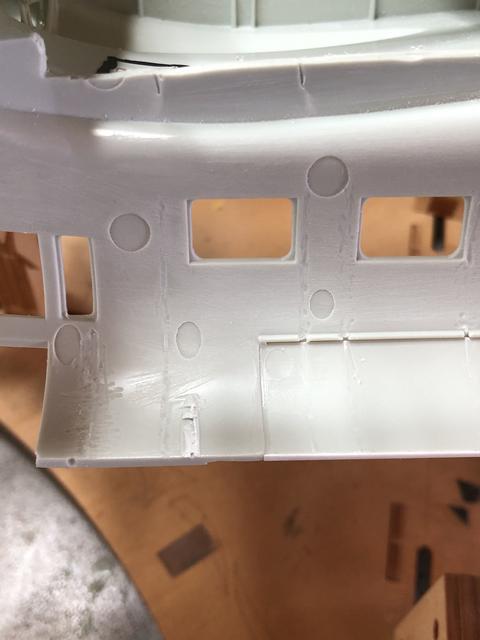
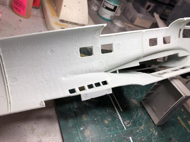
I got a bit vigorous in cleaning up the join between the fuselage and the upper gun opening. It is a very thin join and prone to breaking. I reinforced it with some 0.5mm rod and sheet:
These will be sanded flush when the rest of the interior is done.
I formed some 0.5mm X 1mm styrene sheet around the 6mm ish rod and then inserted into the irregular hole of the forward fuel filler opening. I think I may have cracked this at last!
Regards,
-
Welcome back,
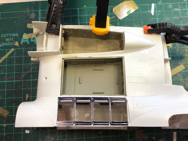
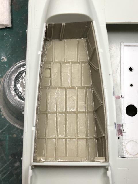
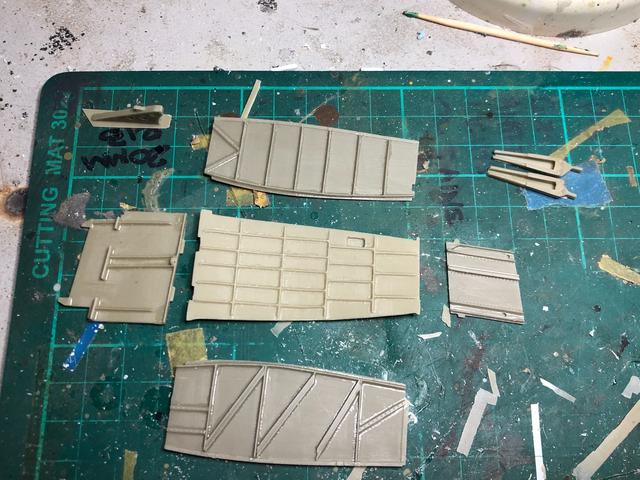
Incremental progress but progress nonetheless. I started cleaning up the interior surfaces:
The MLG, fuel cell compartment and fuel cell fillers have all had a first coat of RLM02 and finally been installed:
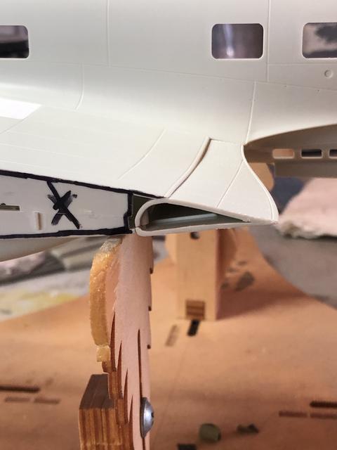
The wing cross section was removed with a Dremel cutting disc and tidied up before the resin piece was inserted into the opening. There is still a little clean up but I am happy thus far:
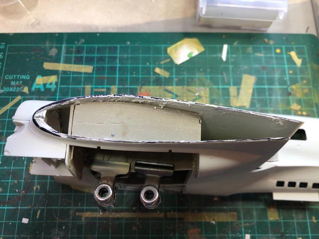
The inner flap was cemented in place and will have a small resin piece covering over the hole:
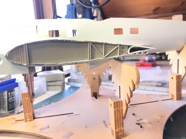
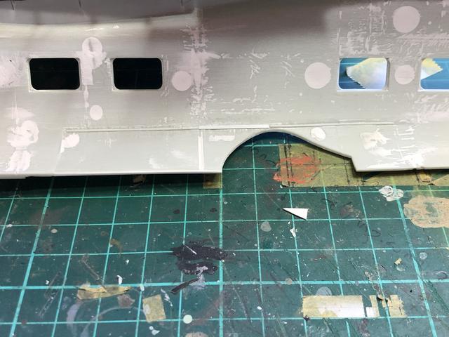
The fix to the upper wing was installed some time ago. I wanted to address the forward opening but it didn’t go quite to plan and will require revisiting. I have a plan to line it with thin styrene strip around the opening and fill the outer edges. It may be extreme AMS but I would like to get it right as it is such an obvious aspect:
Regards,
-
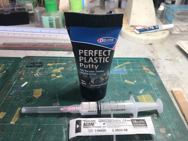
If like me, you like the properties of PPP but struggle with a delivery system and are always on the lookout for modelling hacks, try this. If you know someone in the medical game, or even a friendly chemist, ask for a small syringe (5ml should be fine) and a blunt “drawing” needle. Decant (if that is the correct word) some PPP into the syringe and apply. The needle cap should keep it fresh and you don’t need to fill the syringe, which can be washed in water after use if you wish. Saves wastage and clean up.
Regards
- Jeff T, D.B. Andrus, Whitey and 6 others
-
9
-
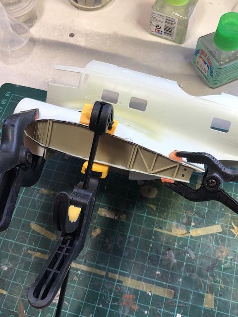
Well it’s in. The old adage about a plan not working after the first shot is true. After fiddling for two hours with my planned install, I went with the front first then the roof and rear pieces put together and shuffled into place. The sides were then put in but it cost me some details and some alignment issues. This was mainly caused by not having the forward piece at as close to 90 degrees as you can. If it is out it will throw it all out. Styrene strips and card will fix the errors with some putty. If I ever build another, I shall ignore the instructions and put the MLG in place before joining the wings:
Regards,
- BradG, mozart, Rick Griewski and 1 other
-
4
-
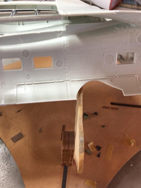
Just realised I forgot to include the progress (sort of) for the upper wing fuel area. The new piece was inserted into the wing and glued section at a time to conform to the wing contour. Unfortunately in drilling out the forward opening, I overlooked it so a piece of card was shaped and inserted into the hole. It will be smoothed out in the putty and sanding works:
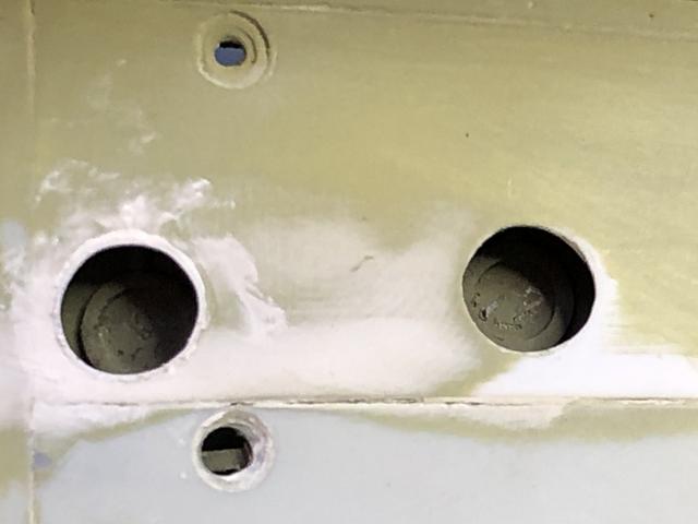
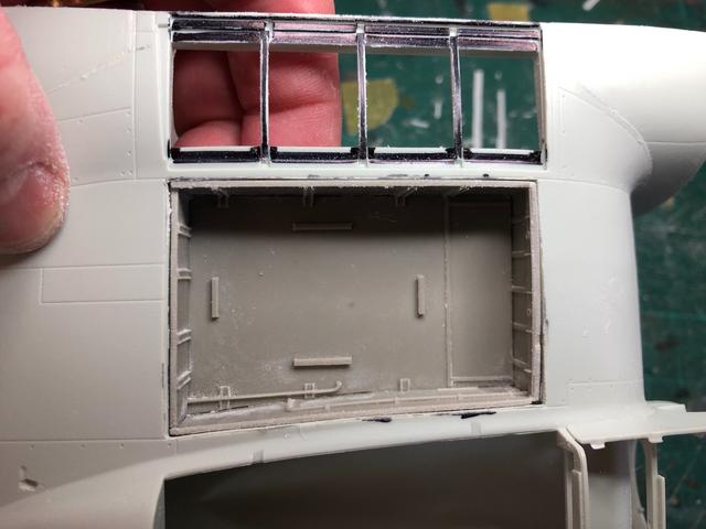
The interior has had some more of the styrene ribs removed to accomodate the two fuel filler port boxes. These will be thinned in a box shape some more to get the fit level:
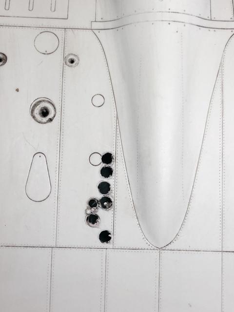
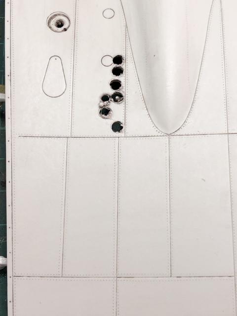
The inspection ports have been drilled out to accept the PE covers and they will sit flush: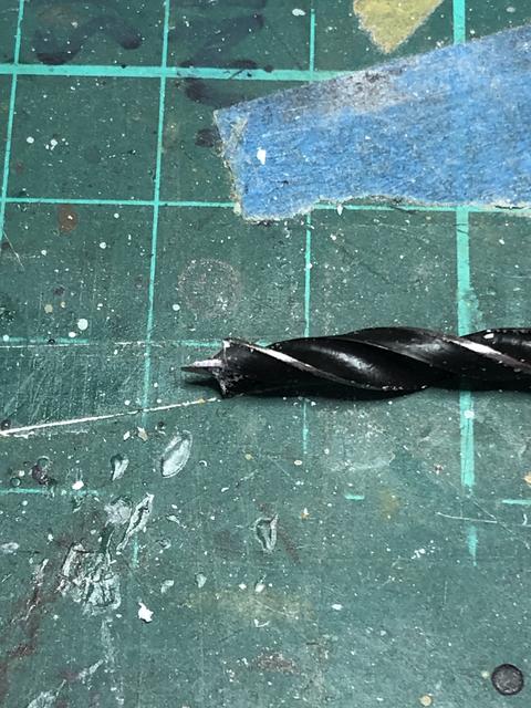
Thanks for looking in.- mozart, Rick Griewski, LSP_Kevin and 1 other
-
4
-
Welcome back and thanks for looking in,
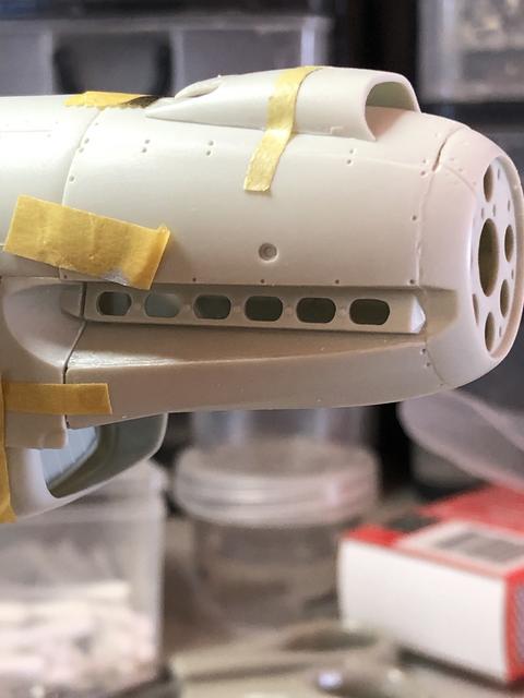
After a comment at last week’s club meet (you cut me deep Shrek), I thought I should document my minimalistic approach to progress. The fuselage upper gun position piece has been bisected and added to the fuselage:
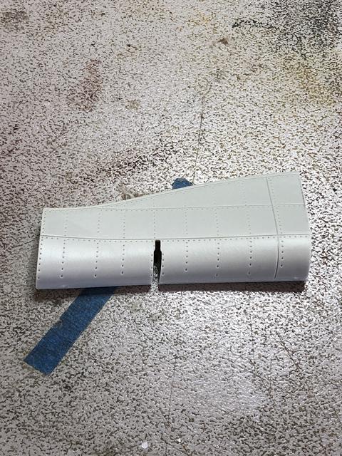
The flap section has also been assembled and test fitted to the wing:
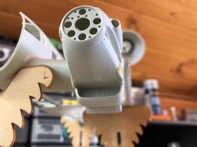
The engine assembly had its various cooler flaps and covers test assembled and dry fitted:
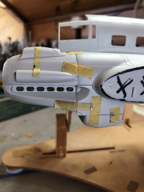
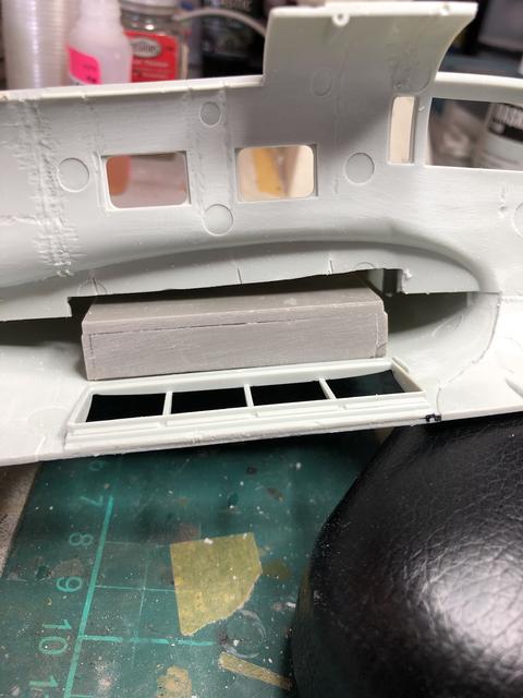
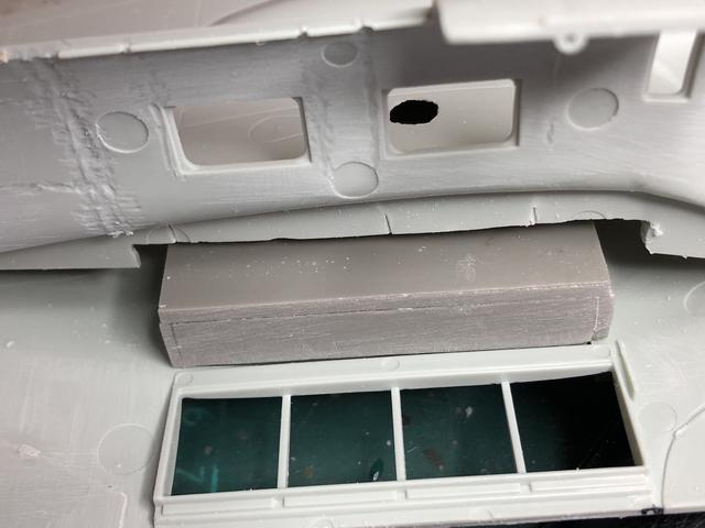
Work on the fuel cell insert continues with some card shim added to get the fit even:
It was then that I realised the wheel bay assembly would need to be installed before the fuel cells. I have followed the HPH instructions but probably should have deviated and installed the MLG bay before cementing the wing halves together. Anyway, after some considered dry fitting and a couple of hours,I came up with a sequence to install which will hopefully prove the least testing:
I also removed all the alignment peg positions on the fuselage as they are superfluous and will need tidying up as well:
So forward to the end of the year!
- BradG, Gazzas, mustang1989 and 2 others
-
5
-
Nice start,
That cockpit set looks great, even if it is nude! Looking forward to seeing this progress.
Regards,
-
10 hours ago, Thomas Lund said:
Cracking piece of work !!
I always shy away from riveting since I cannot help obsessing about getting it right, especially where two lines meet. Is there some kind of trick to that ? What I see of yours looks dead on...
Many thanks,
Yes, obsessing over getting it right. I am the same, hence the practice run (or runs!). Right angle joins are one of the things that still evade me. Here I merely followed the panel lines along the entire length and trusted in dumb luck. There are many that are too close together but it is something I am going to have to chew over. Possibly placing the point in the last indentation of the first line and running at 90 degrees is the answer? I remain open to answers from the floor.
Regards,
-
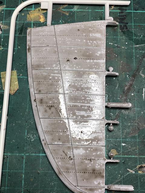
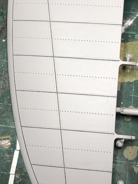
Going to have a go at riveting the Heinkel. Well, the half Heinkel with a quarter wing. Practicing on the surplus parts with the RB 0.75mm rivet-r. Just following the natural panel lines as practice. Then a Flory Wash and Dullcote the bring them out. First off was bare plastic on the wing, then primer on the stab before running the rivet-r along the lines. I lack a bit of consistency in pressure so that is a learning point. Not that you need much, just consistent:
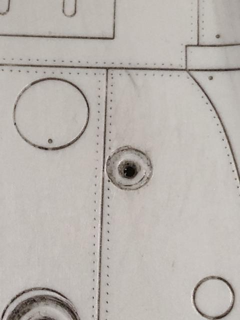
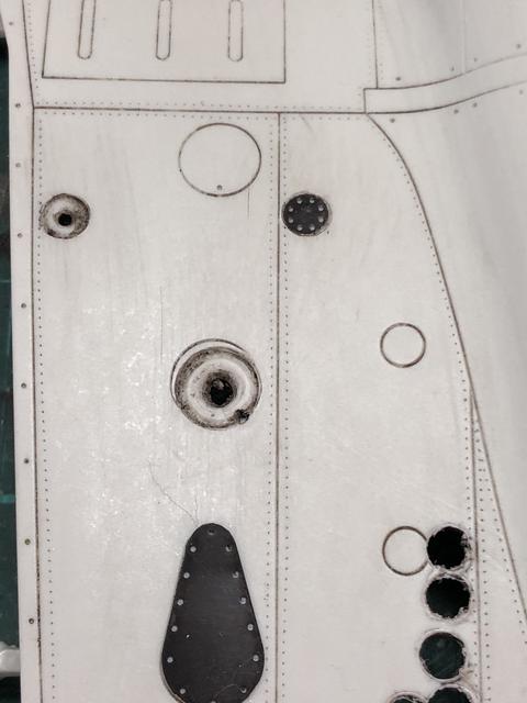
The Eduard PE sits slightly proud of the plastic if just glued on top. I got a small set of drills to remove some material (about 1mm) in a circular pattern and the PE just drops into place and sits flush:
Rivet plans for the P are very scarce so it will be a rudimentary rivet job. I have a set that Ralph used in his build a couple of years ago to assist me, so stay tuned!
Regards,
-
Great work Sophie,
Welcome to the forum from Australia. You have some great kits in your lineup, you obviously have good taste!
Like many, I ditched Photobucket and went to another service. I use Postimage, www.postimg.cc as it’s free and easy.
I look forward to following on.
Regards,
-
-
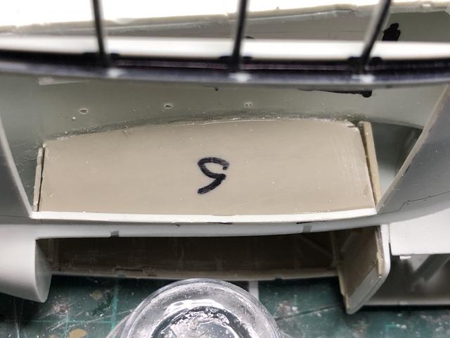
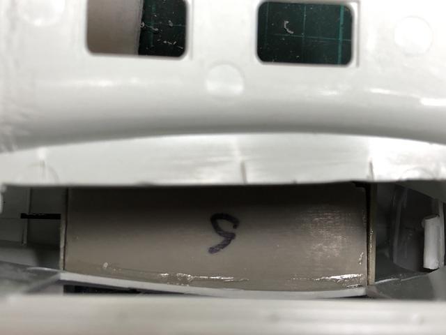
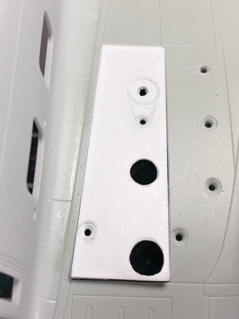
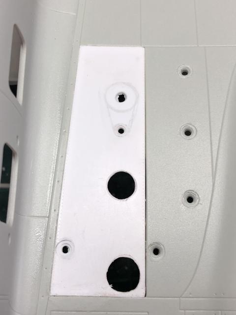
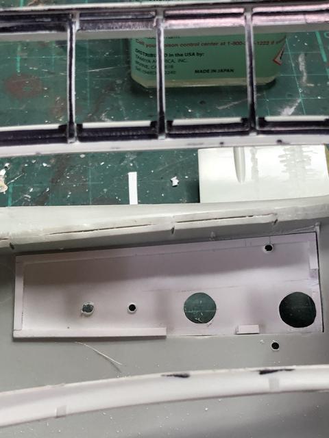
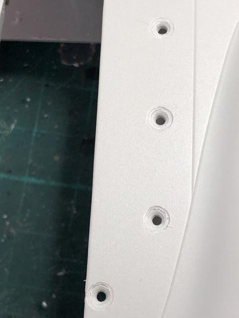
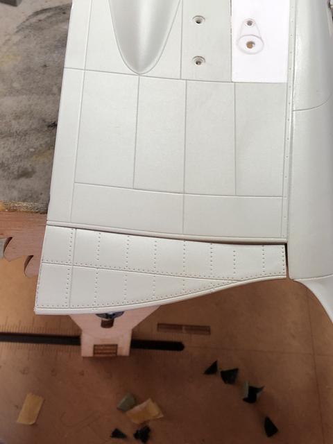
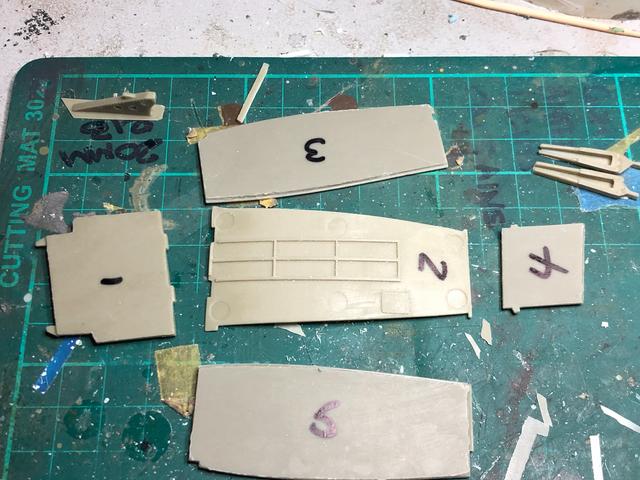
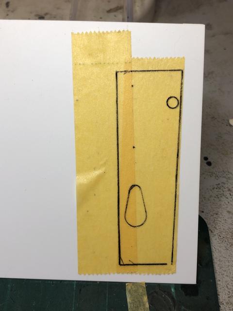
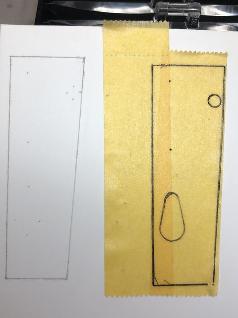
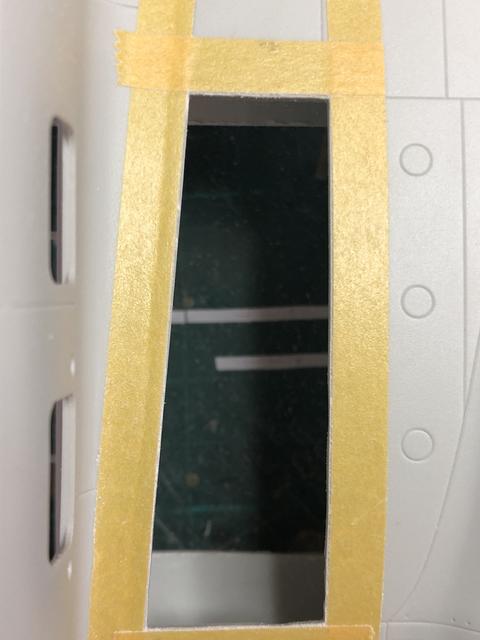
So twelve days of procrastination and I have finally started work on the fuel filler ports. The tape template was removed from the wing and placed onto a piece of 0.50mm styrene sheet. I then pinpointed the panel corners, centre of the open fuel cell doors and other detail using a needle point scribe. The template was removed and the dots joined to make the panel outline, with details relief brought out using a 0.5mm mechanical pencil. This way, I still had the intact template if I made an error:
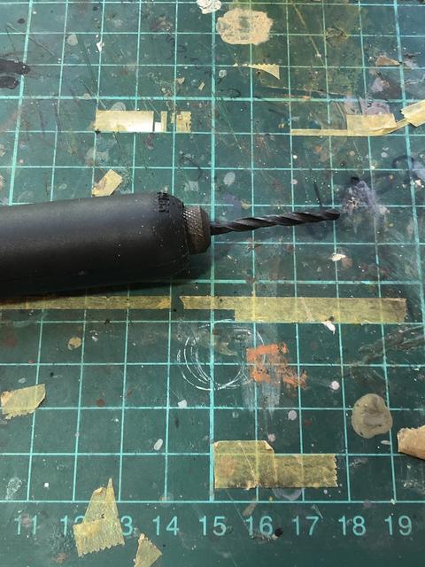
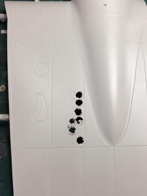
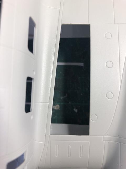
I test drilled the other spare wing piece to get the right speed and drill size to chain drill the panel I needed removed with my faux Dremel. Happy with my choice,I drilled out the actual piece, removing the waste with sprue cutters:
I then carefully taped the borders of the panel and using a flat file, sand stick and a lot of patience, I remove material to the tape edge:
Until I was left with this result:
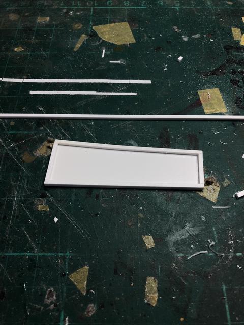
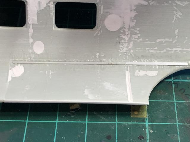
The replacement 0.50mm panel was edged with 1.5 x 1.5 strip to provide a good anchor the the plastic around the opening. Some test fits show the work has paid off and I am close.I will impart a slight curvature in the new styrene to match the wing shape and fix the smaller rear end first, allowing it to set up before moving forward to complete installation.
Regards
- BradG, mozart, mustang1989 and 7 others
-
10
-
-
Welcome back,
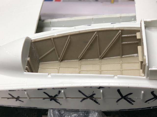
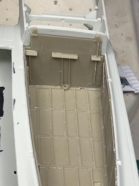
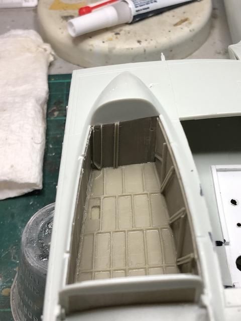
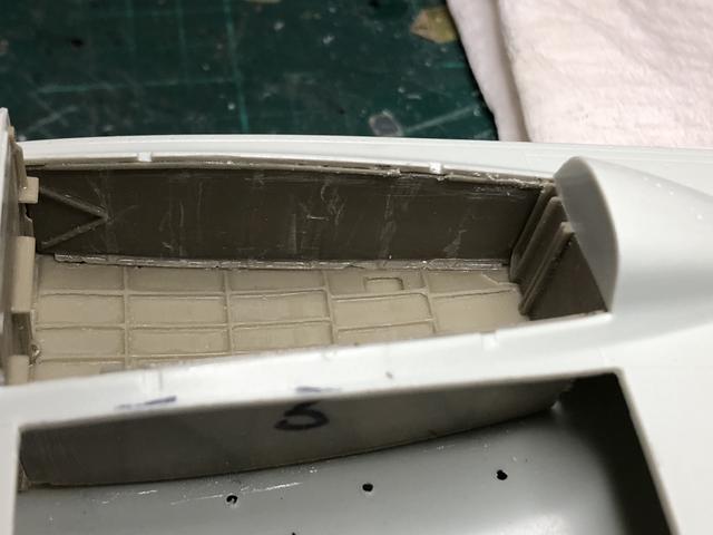
I have removed all the internal moulded detail of the fuselage as per the HPH instructions. The injector pin marks will be filled, the wing concealment fitted and putties before it is all sanded:
The lower wing cutouts for the fuel cell appear to be suitable. My only concern is the inner face of the insert may extend to far inboard and impinge on the false fuselage wall I have to add to hide the wing area:
I have sanded the inner face of the resin almost as far as I dare. I will have to dry fit the wing conceal to see how I go:
The HPH instructions require careful reading in conjunction with the kit and the Eduard instructions. The HPH ones appear to jump around a little, with some sections of Eduard PE having been fitted prior to the resin installation of the HPH set. The bomb bay area is a case in point with the PE inserts in the lower openings fitted before the resin internals.
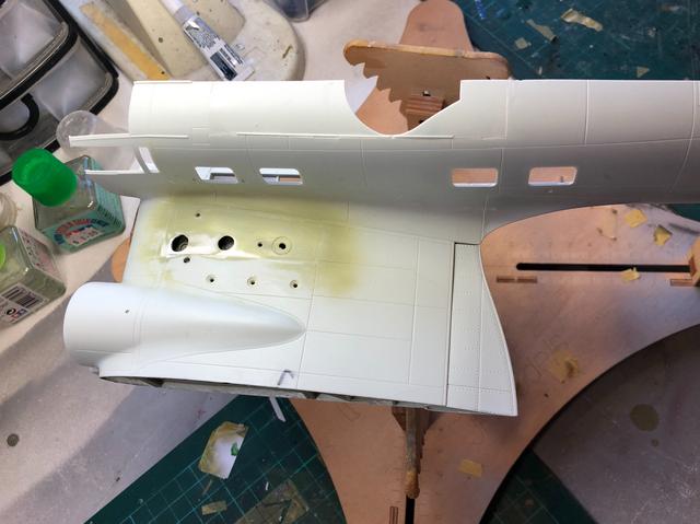
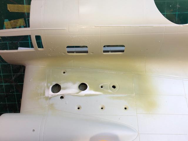
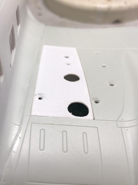
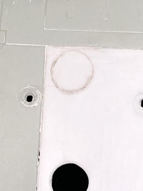
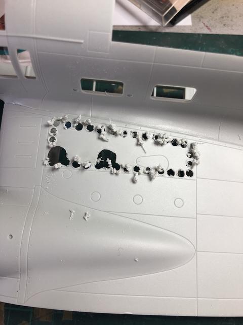
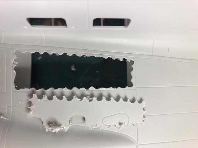
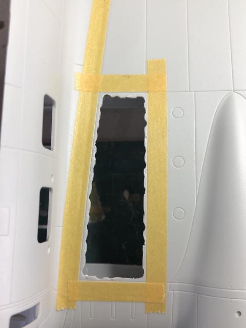
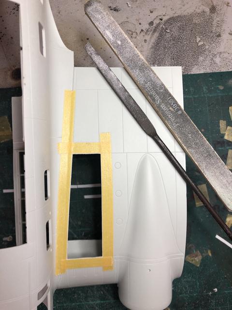
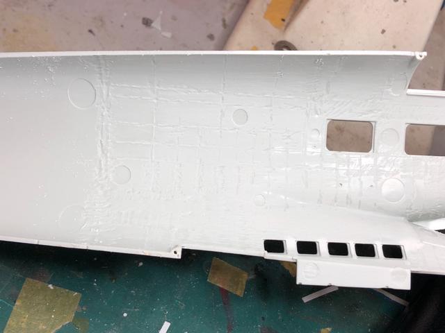
I have attempted to thin the plastic to scale in the fuel cell openings in the upper wing. The internal is okay and surely a better scale thickness, however in doing so I have butchered the round openings:
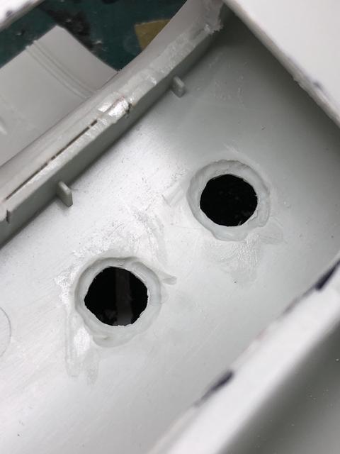
I shall pause to consider but I believe the fix may be removal of the entire upper panel area and replacement with styrene sheet, drilled and scribed with the resin attached to the new skin.
Regards,
-
Absolutely first rate result. The finish is flawless.
Regards,
1/48 Heinkel 111 H-3 ICM kit
in Non-LSP Works
Posted
Very, very nice.
Thanks for sharing.