

DerekB
-
Posts
86 -
Joined
-
Last visited
Content Type
Profiles
Forums
Events
Posts posted by DerekB
-
-
What a fabulous build Marcin! Thanks for sharing it with us. The toolkit complements the maintenance work! A most enjoyable tableau of an attractively-proportioned racer!
-
OOH Splendid! I was waiting with bated breath for the "bright scarlet*" to appear! Looks wonderful!
* according to Charles Mendenhall -
The engine looks magnificent @Marcin_Matejko! Leaving the cowl panels off will be very rewarding! And leaving the fuselage innards visible will be great too, such incredible detail that you've replicated in there!
-
Love a slick racer, and these were sure slick! Your rendition of monsieur Detroyet looks great!
-
Hi Mike, I have one of these in my stash, so I'm enjoying seeing yours come together! Nice work so far, and great to hear tips from other builders too.
-
This looks fantastic Marcin! Your custom jig is an excellent piece of work, that will ensure alignment 100%! And your clever "up-cylcing" (not just "re-cycling") of parts from other models is very creative! I'm really enjoying watching another of your racing creations come together!
-
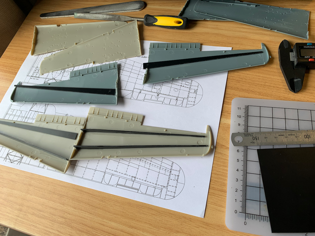
So I was working on the outer wings, sanding off the existing surface detail ready for re-scribing and getting ready to cut and modify the tips. But all this work was too much for the glue seams at the leading and trailing edges, and they eventually split open. The outer wings were just too flexible to take all this work.
So to strengthen them, I decided to add two spars, which I measured and cut from some 1.0mm styrene sheet. They're black because that's what I had.
You can see two sets of outer wings in the photo below... the dark grey set are for this Wirraway conversion. The light grey set are for my "Hot Rod Harvard" project (these will be clipped and modified to represent CAC Boomerang outer wings). A third set (not shown) will be made for my "Gee Bee's Wirraway" project (standard Texan wings clipped by 24 inches at each tip).
-
Excellent work Anthoney, some motivation to keep on with my civvy Hasegawa Mustang, too!
-
-
On 10/29/2023 at 3:11 AM, mozart said:
The answer is…..just about I think!
Totally agree Max! The top-down shot once again shows your skills and attention to detail, as well as the beauty of Camm's lines... perhaps even more pleasing from above than from the side... is that possible?
-
-
Work on the CAD model of the Type B target towing winch is almost complete. The winch drum, traversing screw and "windmill" propeller are all finished, I just need to finish the control panel and re-do a small section of curved surface where the arm meets the gearbox. Here's how it's looking:
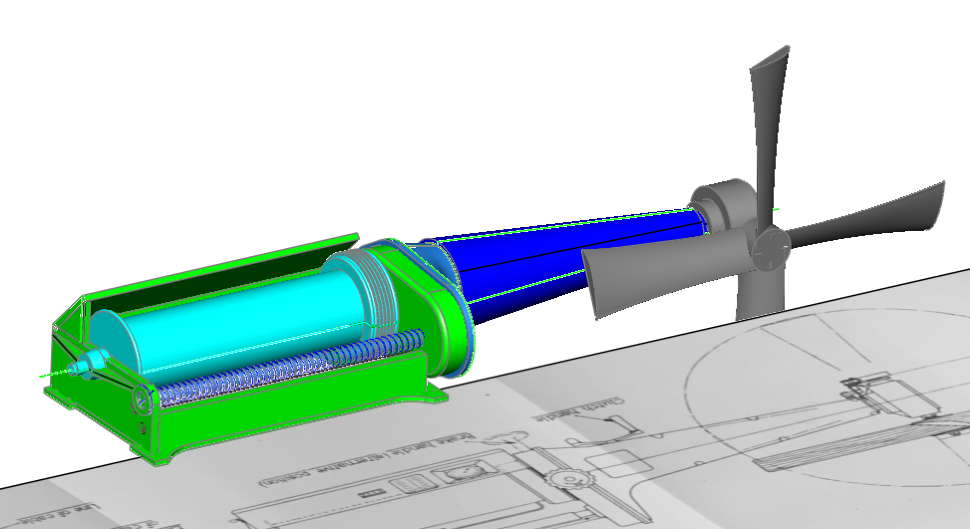
After puzzling over photos, plans, drawings and manuals, I've decided that the winch was mounted on the wooden floor which was below the fuel tank behind the pilot. Of course the fuel tank and radios had been removed, hence the two Mustangs operated by Fawcett Aviation / Illawara Flying services for target towing contracts were always seen fitted with drop-tanks. The winch operator sat with his legs above the winch - this is the only way the winch operator and the winch can fit in the space behind the pilot.
So the first step in modifying the cockpit is to remove the fuel tank and rebuild the floor in this area. In the photo below I've cut out the fuel tank and reinforced the space with some styrene sheet (black). This is a cockpit from the Tamiya kit, which gives me much more detail compared with the basic Hasegawa offering.
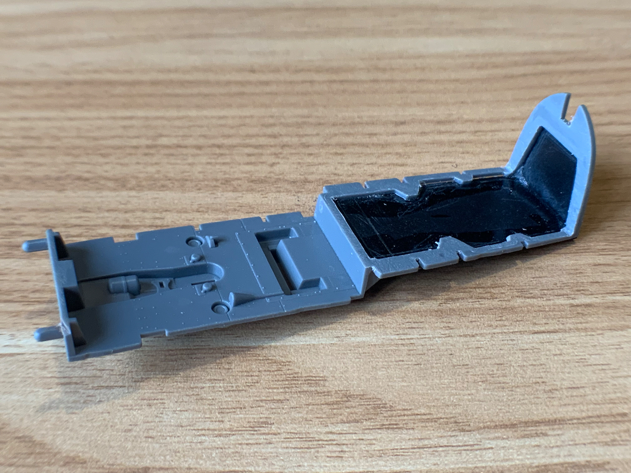
So nothing very exciting happening yet in this area. Next I'll rebuild the floor and get this area ready to receive the winch once I've finished the CAD model and had it 3D printed.
-
@KiwiZac, It's not about to fade away, but it is moving slowly on the back-burner. I've been having some online chats with Matt Denning about this plane, and it turns out the modified outer wings retained the same trailing-edge angle as the original Harvard wings, so that will make the project slightly easier...
-
Rhinoplasty continues...
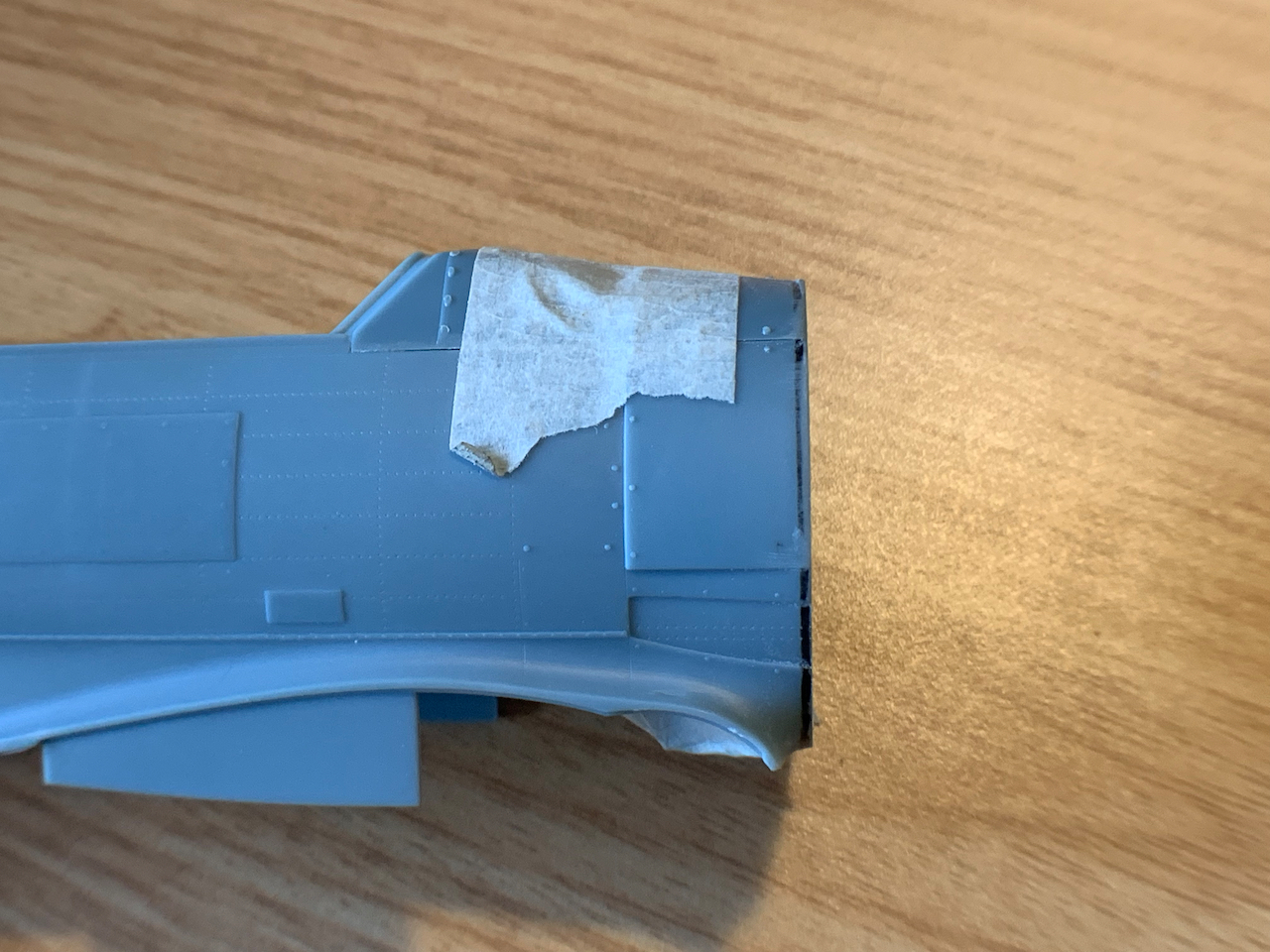
I've trimmed the fuselage cowlings (the fixed panels just aft of the engine cowling) to the correct length, now I need to blend them in to the exactly circular shape of the engine "dishpan". You can see the upper panels in front of the windscreen need to slope down more sharply, and the "jowls" around the wheel fairings need to be shaped to the correct profile. The KittyHawk T-6 kit is poorly shaped around the fillet between the wheel fairings and the underside of the forward fuselage - wrong even for a T-6.
Not obvious is that the sides of the fuselage cowl also need to be expanded outwards to meet the dishpan.
Fuselage cowl trimmed to length:
The view from the front, with the Wirraway “dishpan" in about the correct location:
And from below the nose...
- LSP_Kevin, Fanes, patricksparks and 3 others
-
 6
6
-
48 minutes ago, MikeMaben said:
Nice to see this back on the bench Derek
 , have you a particular subject/scheme in mind yet ?
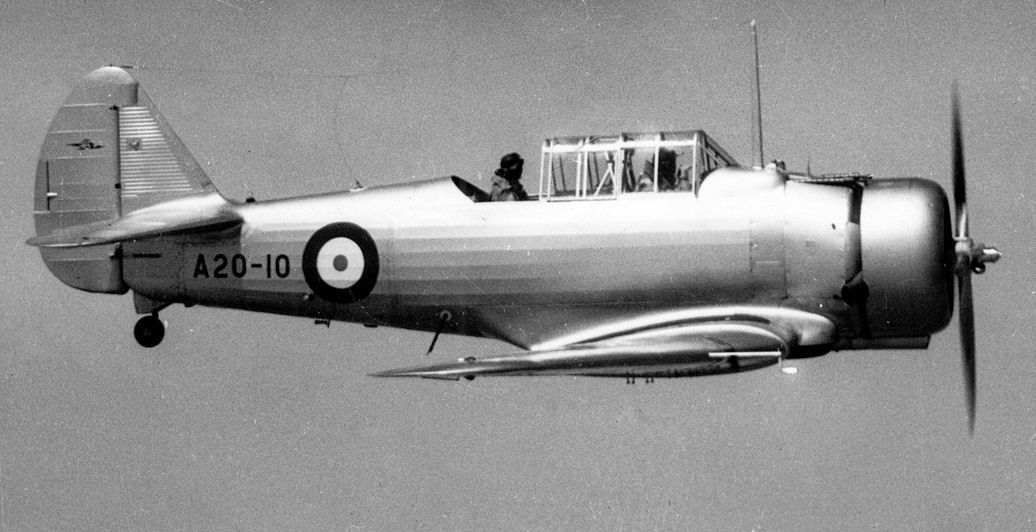
Hi Mike, yes, this will be finished as A20-10, the oldest Wirraway still in existence, which I helped restore for static display back about 9 years ago.
Here she is back in early 1940:
And here she is when we rolled her out at the Moorabbin Air Museum in September 2014:
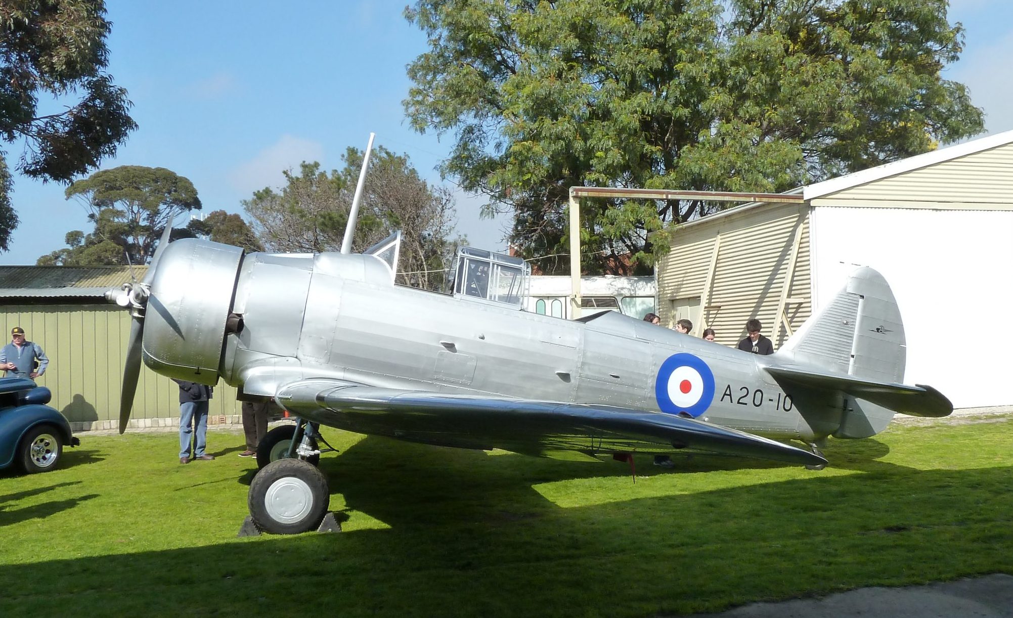
So references are not a problem!
-
Still working away slowly at this big Wirraway, while building some smaller ones (see on Britmodeller if you're interested).
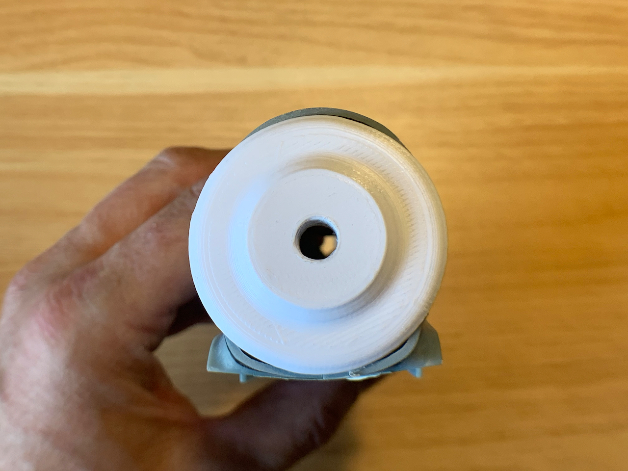
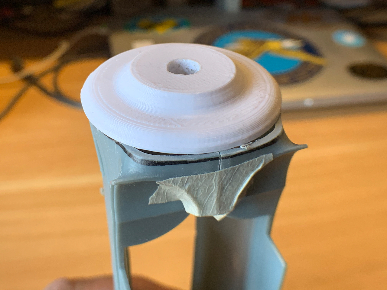
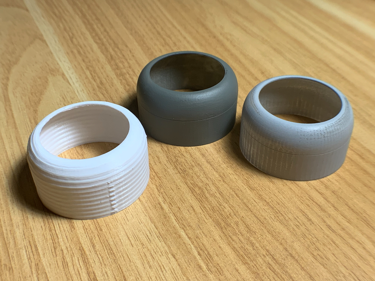
The Wirraway engine cowl was significantly different to the T-6/Harvard cowl. It is perfectly circular and does not flare out towards the rear. So I've been experimenting with 3D printing... below are three different 3D printed cowls. On the left (white) an early attempt in FDM, clearly not acceptable. At the rear (dark grey) is a first attempt via Shapeways which was very pleasing. But the wall thickness was only 0.6mm and it was too flimsy. Then on the right (light grey) is another print from Shapeways, with the walls thickened up to 1.4mm and this was nice and solid. It needs another coat of Mr. Surfacer and a little more sanding to remove the printing artefacts on the surface. I probably should have increased the resolution of my model, but it will work fine with some more help. So the basic shape of the engine cowl is sorted, now it just needs some scribing and rivets added.
More to come...
- patricksparks, scvrobeson, MikeMaben and 8 others
-
10
-
 1
1
-
-
1 hour ago, James Rademaker said:
…I have used the Tamiya cockpit sprue 3-4 times to “upgrade” the Hasegawa Mustang. It fit’s pretty well…
Jim
Thanks for the suggestion Jim. In fact I did already get hold of a Tamiya cockpit sprue and it’s going to get hacked around pretty severely to squeeze in the second seat and the winch body. I needed a cockpit set which included the floor below the fuel tank, since that is where the winch will sit (somehow). The Tamiya kit includes this detail, so it is ideal for what I need. Good to know it can fit in there!
-
I'm still working on the 3D CAD for the Type B target towing winch, but in the meantime I've shoe-horned the Aries resin wheel-wells into the wing. I think it's a big improvement, getting rid of the "boxed in" sides on the kit's moldings.
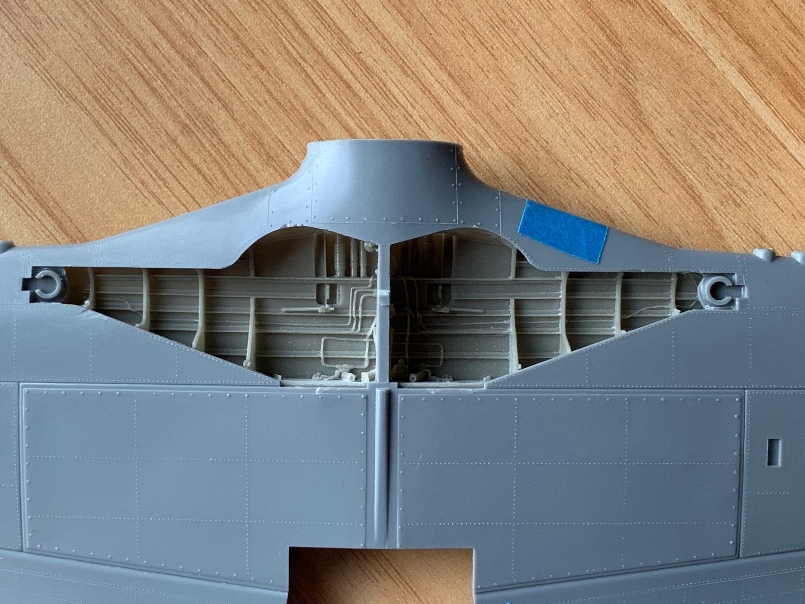
Still needs a little tidying around the edges, and I was a bit too enthusiastic filing too much off the front edges of the resin molding, but it's very difficult to see from the outside.
Here's the view from inside, you can see how I needed to remove a section of the inner "rib" of the upper skin. But overall the fit worked fine.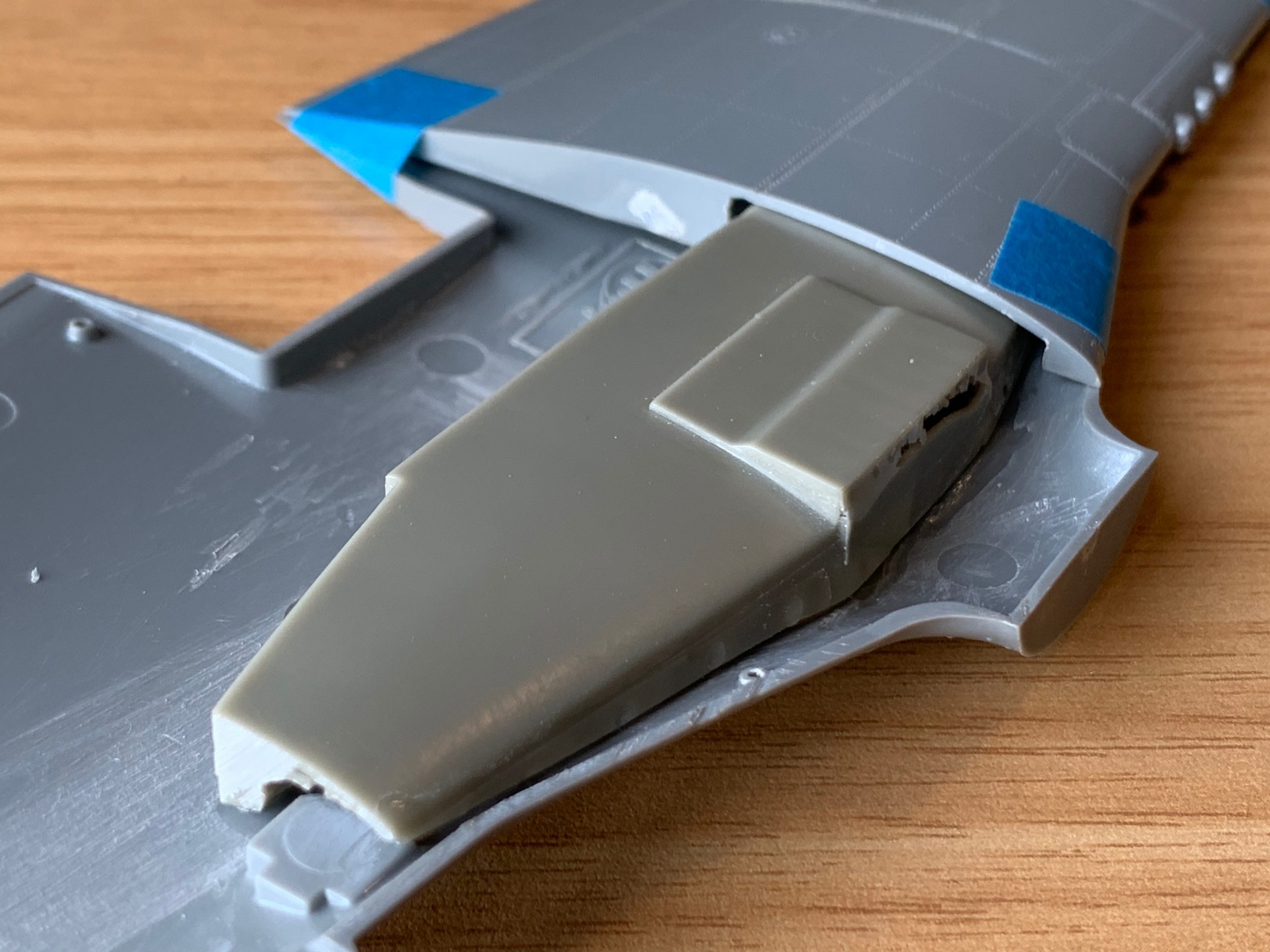
I took the outer ends off the resin part and left the Hasegawa undercarriage mounting holes in place. They are far from scale accuracy, but it saves me having to find an alternate method to attach the main undercarriage legs.
- MikeMaben, KUROK, scvrobeson and 4 others
-
7
-
Doing some more research for the cockpit of this build, I contacted the owners of the full-size plane. Glad I did... it has a Mustang seat in the rear position!! Plus the instrument panels don't match any standard Harvard or Texan I've seen. So now to order a resin Mustang seat, and figure out how to replicate the instrument panels...
-
First step in converting the T-6 wing to a Wirraway wing... I've trimmed a wedge from the inboard end of the outer wing panels, so the trailing edge is now straight and the leading edges have increased sweep angle. This was about a 30-second job on my woodworking disk sander. The 120-grit paper cut through the wing like butter, more melting than sanding! I taped a Lego block (2x6) under the wing-tip to retain the correct dihedral... simple.
The Wirraway wing is almost identical to a BC-1 or a Harvard Mk.1 wing in its shape and structure (apart from the additional hard-points added to the underside by CAC).
The inboard end of the aileron cut-outs matches the Wirraway position, and the landing lights also match the position for the Wirraway wing. Next step is to modify the tips and then re-scribe all the surface detail...

-
The Wirraway was armed with two forward-firing Vickers Mk.V guns. Gas Patch Models sell a lovely replica Mk.V but unfortunately they feature the water-cooled barrels. So after a bit of hunting around I found that the Air Master "Japanese Type 97" gun barrels would nicely replicate the air-cooled barrels of the Vickers Mk.V

So after carefully hacking off the water-cooled barrel, I drilled and glued the lovely brass perforated Air Master barrel onto the first of my Mk.V guns. Sadly I lost the forward mounting point (will have to be more careful on the second gun). The Type 97 barrel is 1mm too short, and I still need to add a conical flash suppressor at the muzzle, but I'm pleased with this outcome.
-
3 hours ago, KiwiZac said:
Any new updates to report, Derek? An RAAF vet P-51D just crossed the ditch back home (flew past my place on the way) so I'm in need of an Aussie pony fix!
Thanks Zac, still working on this one, but slowly. Yes, I noticed Doug has a shiny new pony at Wang!
This model actually lives on my yacht, which is in Geelong, and I live in Melbourne, and sadly haven't visited the yacht for several months. I did receive the Aries undercarriage resin, but no pictures yet. And I was trying to get that little red Mustang done for the Matchbox 50th GB on Britmodeller... but missed the deadline sadly, still going to get it finished...
https://www.britmodeller.com/forums/index.php?/topic/235104749-pk-13-p-51d-mustang-racer-fast-red/
-
...well this one is moving slowly...
I'm still playing around with the CAD model of the winch, and trying to figure how the rear seat and the winch drum managed to both fit behind the pilot's seat.
Meantime, I've decided to dress up the wheel wells. Here's what I'm starting with from the Hasegawa kit. This will all get cut out and replaced with some nice resin from Aries...

- scvrobeson, KiwiZac, themongoose and 2 others
-
5


Williams Bros 1/32 Gee Bee R-1
in Ready for Inspection
Posted
Nicely done Ken! I have one of these in my stash, will have to drag it out some time.