

Mr Creosote
-
Posts
199 -
Joined
-
Last visited
Content Type
Profiles
Forums
Events
Posts posted by Mr Creosote
-
-
13 hours ago, Biggles87 said:
Looks like you've killed two birds with one stone there. I remember thinking that the wings looked a little flat when I taped mine together when I first got the kit.
Merry Christmas.
John
John,
I think that's right. My reference is Aerodata International "Fighters Of World War II Vol 1 " published in 1980. The Hurricane drawings show the top, span-wise datum line, of the wing panels being flat, with the bottom, span-wise datum line, of the wing tapering up,3 1/2 degrees to the tip. At any rate it looks right to me.
Merry Christmas.
Richard
-
On 12/21/2020 at 4:48 PM, monthebiff said:
Nice work indeed, our of interest how is the fit of your wing assembly when married to the fuselage at this stage, very interested tongue!
Regards. Andy
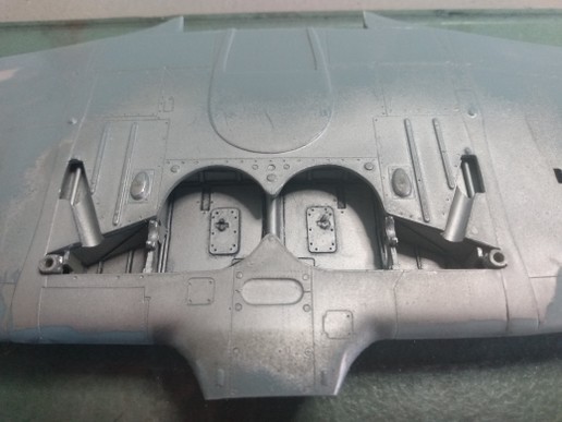
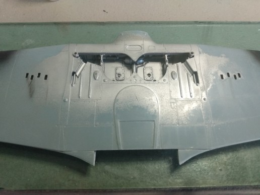
The fit of the wing to the fuselage is better than I expected it to be. For me to get the best fit took some dry fitting and minor trimming. All of this work was done at the front and rear joins of the wing center section. It was no big task and is sort of to be expected of a short run kit. The center section area was the first area glued up. CA was used as an adhesive. At that point the wing roots themselves had large[ish] gaps with the widest being about a 1/16th". I checked the alignment at this point and decided the wing did not have proper dihedral. Granted Hurricanes don't have much dihedral they do have some. To correct that I applied a good amount of CA into the gaps and held the wing to the wing root until the CA set up sufficiently to hold the gap closed. Excess CA that squeezed out of the join was wiped away with a Q-Tip/cotton bud before it set up. This was done one wing at a time.
So in short the wing roots at this point will only require a bit of attention to get them sorted.
Thanks.
RD
-
The wing and fuselage joined up.
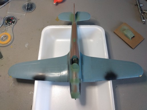
The fit up was better than I expected. Cleaning it up shouldn't be too bad.
RD
- Pete Roberts, MikeMaben, Iain and 4 others
-
 7
7
-
5 hours ago, MikeMaben said:
Looking good RD


Thanks. I appreciate that.
-
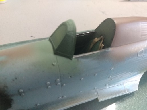
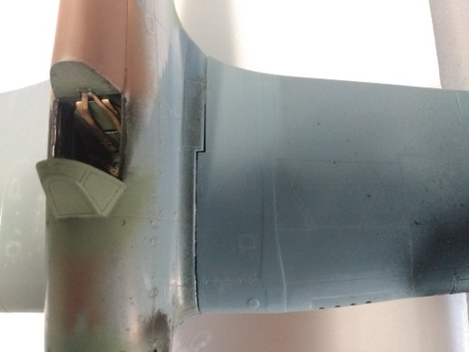
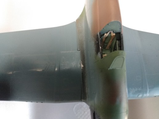
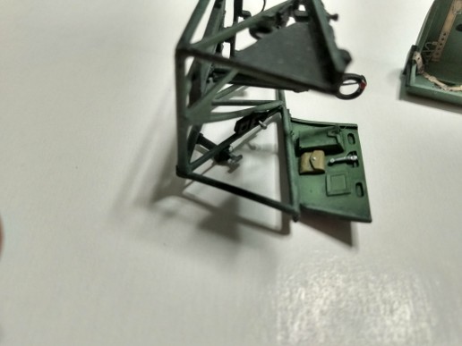
So. Picking up on this project I re-did the Sutton Harness in order to make it a bit more accurate. The windscreen has been added and faired in. The framing on the inside of the windscreen was masked and painted prior to fitting.
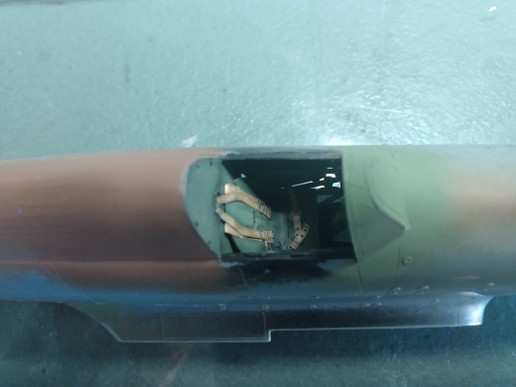
Another view. Not the greatest pictures but I think you'll the general idea.
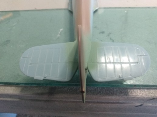
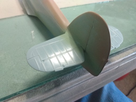
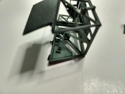
The tail planes have been added. They are held firmly on by use of brass tubing "spars" with matching holes drilled through the tail planes. There were gaps between them and fuselage. These were not too bad and easily filled and finished.
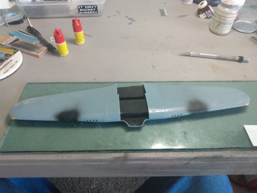
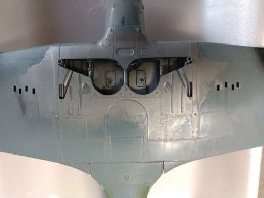
The wing prior to mounting. Black sprayed in the center section to block visibility into the lower section of the cockpit. The black on the landing light sections as a check on landing light cover fill and fit.
I am coming in to the short rows as far as assembly is concerned and then its on to paint.
Thanks for taking a look.
RD
-
On 11/2/2020 at 8:09 AM, Greif8 said:
Looking good! I had a (mostly) good time building my PCM Hurricane and I hope you have a great time as well.
Ernest
Thank you. Yours looks great.
RD
-
On 11/30/2020 at 8:28 PM, LSP_Kevin said:
Done!Kev
Thank you!
RD
-
Admins please move this to Works In Progress.
Thanks.
-
Thank you. Yours looks great.
RD
-
The instrument panel after being fit and glued up into the fuselage. Not the best picture but I think it serves the purpose. To try to get a better fit and bond the forward or front was beveled somewhat. The gloss at the join is some CA that came through. Clear flat was used as a fix even though I doubt that edge would be visible once complete but you never know.
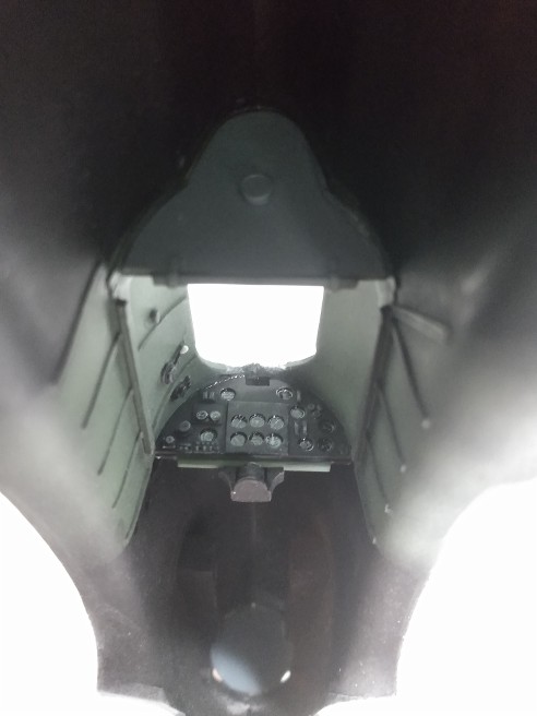
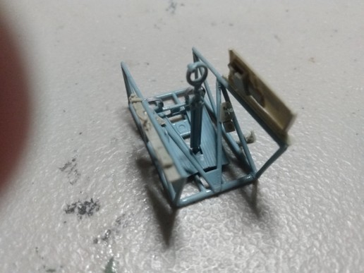
The cockpit frame work and seat painted up and about ready to install. The lap belts were installed the wrong way around. I corrected this later. These are Eduard's Early RAF Seatbelts -Steel. [323872]. Prepainted and very user friendly.

The build is rolling along. More progress shots soon.
RD
-
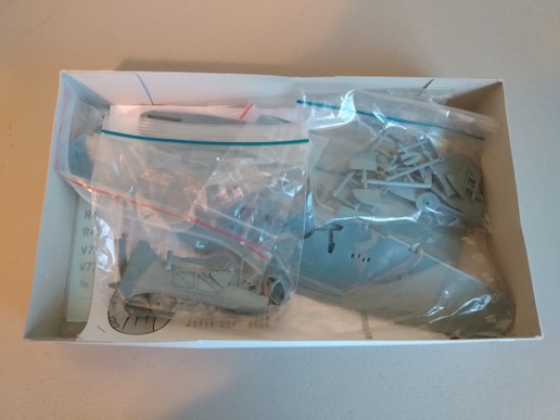
I have started the build. Once I started sorting out the cockpit parts I noticed that the photoetch was gone. I thought ,at first, that I may have to abandon this project, at least for the time being but decided to look through the instructions to see what photoetched parts went where. As it turned out it was the instrument panel, seat belts, rudder pedal straps and radiator grills and detail. I have mesh for the radiator, etched seatbelts in the stash, a choice of materials for the rudder pedal straps and either buy a Yahu or other instrument panel or scratch build one.
I decided to attempt to build the instrument panel first. I have the materials and tools so its worth a shot.
I made sheet plastic blanks using the kit's plastic instrument panel backing. I guesstimated the dimension of the flying panel. For reference I used the drawings in Aerodata International's "Fighters of World War II".
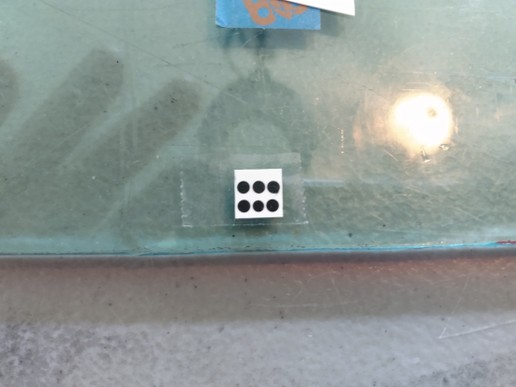
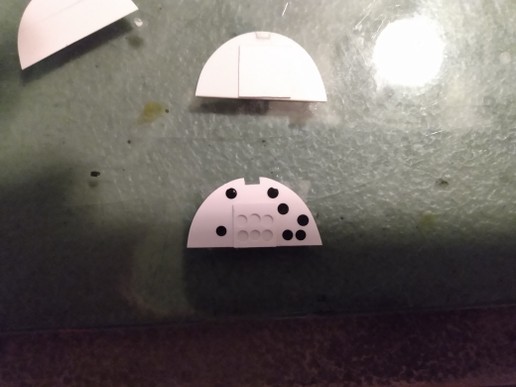
The flying panel was first. I punched disks from black decal and applied them to the panel as template guide for punching the holes in the sheet styrene. I did the same for the rest of the instrument panel. The hole size was determined by the size of the instrument decal going in that location. I am using Mike Grant decals for the instruments. Switches were made using Evergreen strip and shapes or for the smaller electrical switch panels some Reheat photoetch was used.
The starting point:
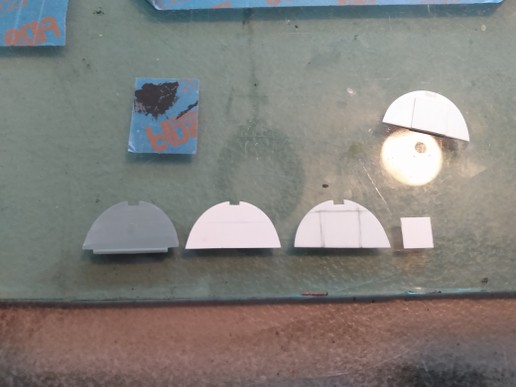
Decal disks on the flying panel:
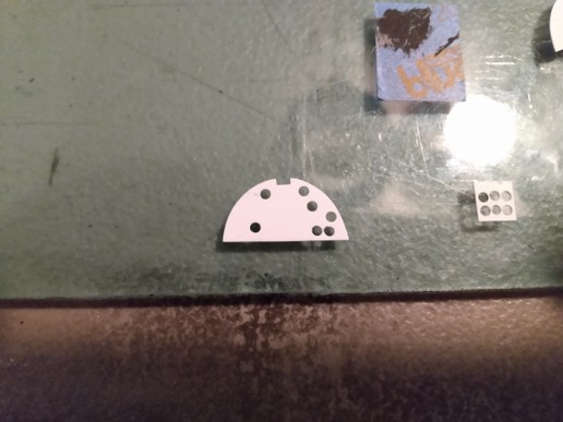
The flying panel instruments punched and the being used to aid in locating the other instruments as accurately as possible.
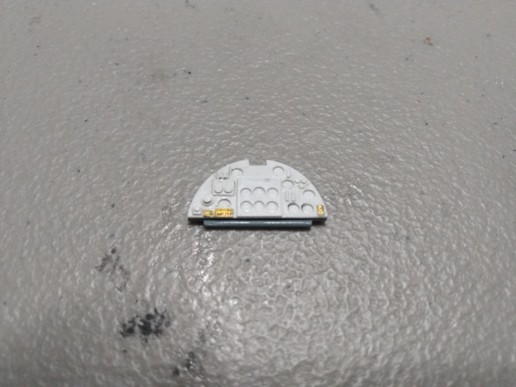
Panel completed. The compass mount and compass are resin kit parts and will be added later.
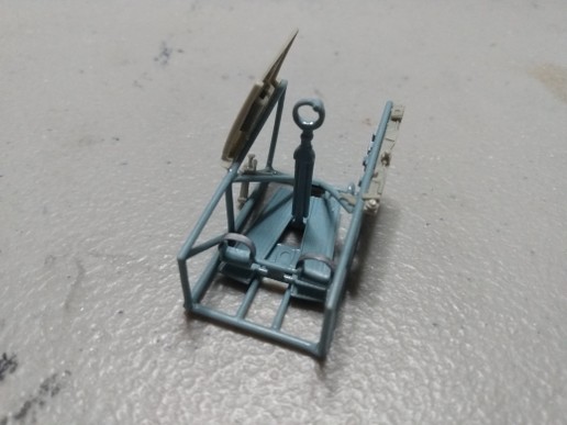
The cockpit frame work basically complete. The rudder pedal straps were made from lead foil. I did, at first, try to use styrene strip but tired of wrestling with it and switched. I think they turned out alright.
More to come.
- Pete Roberts, LSP_Kevin, AlbertD and 13 others
-
16
-
53 minutes ago, Greif8 said:
Hi, No. 303 Squadron is a good choice, very famous squadron! I am going to build either a No. 17 or No. 85 Squadron Hurricane, if my 10 year old Zotz decals are up to it. If they are not then Hurricane will be marked either as a No. 257 or No. 605 Squadron aircraft.
Cheers,
Ernest
Great choices! Looking forward to seeing your builds.
-
5 hours ago, Greif8 said:
Nice choice! I am building the same kit as my second build for this group build. Which squadron do you plan to represent?
Ernest
I am leaning towards P3901 of #303 Sqn. If that was your choice I'll pick another. Probably "Ginger" Lacey's V7357.
-
I'm in with this one. I plan to build it Out-Of-The-Box including using kit decals.
-
-
DNF.
I will be moving this build over to the WIP forum.
RD
-
Work continues on my Mosquito despite other projects that delayed this build.
I have prioritized this build by tackling the time consuming problem areas first.
For this build these areas are the wings and nacelles.
Both wings were warped both span and cord-wise with the port wing being the least warped and the starboard wing the worst.
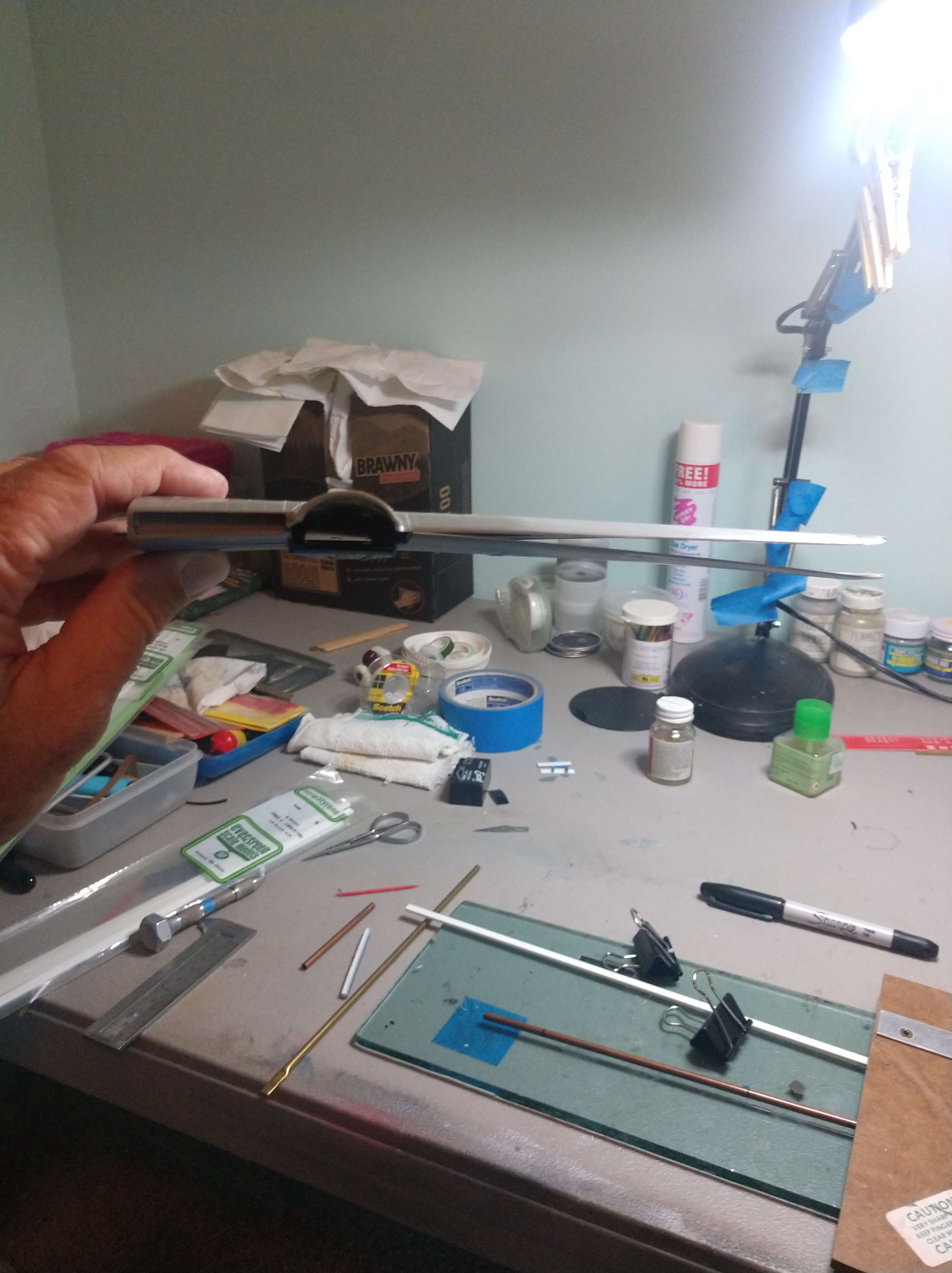
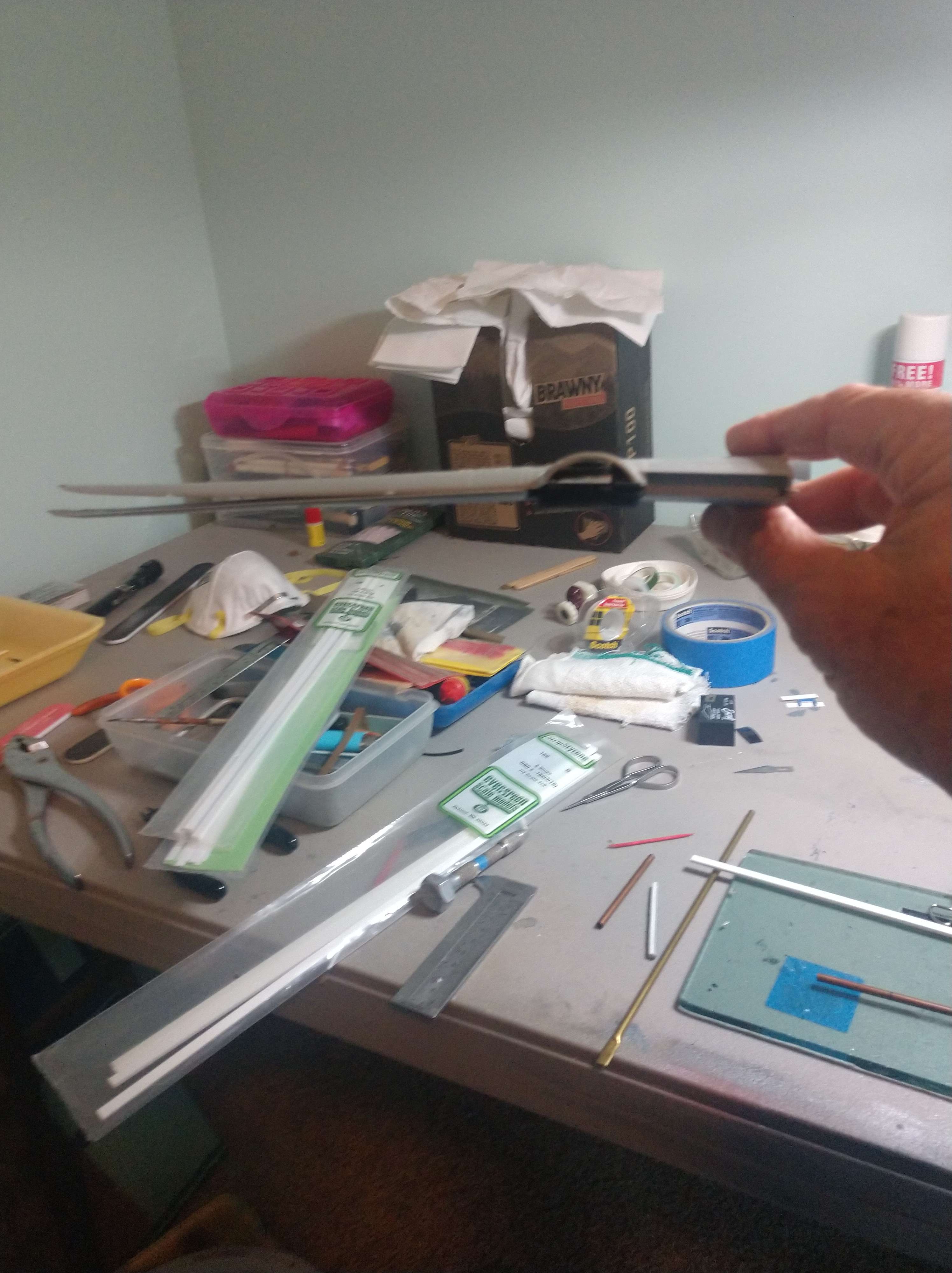
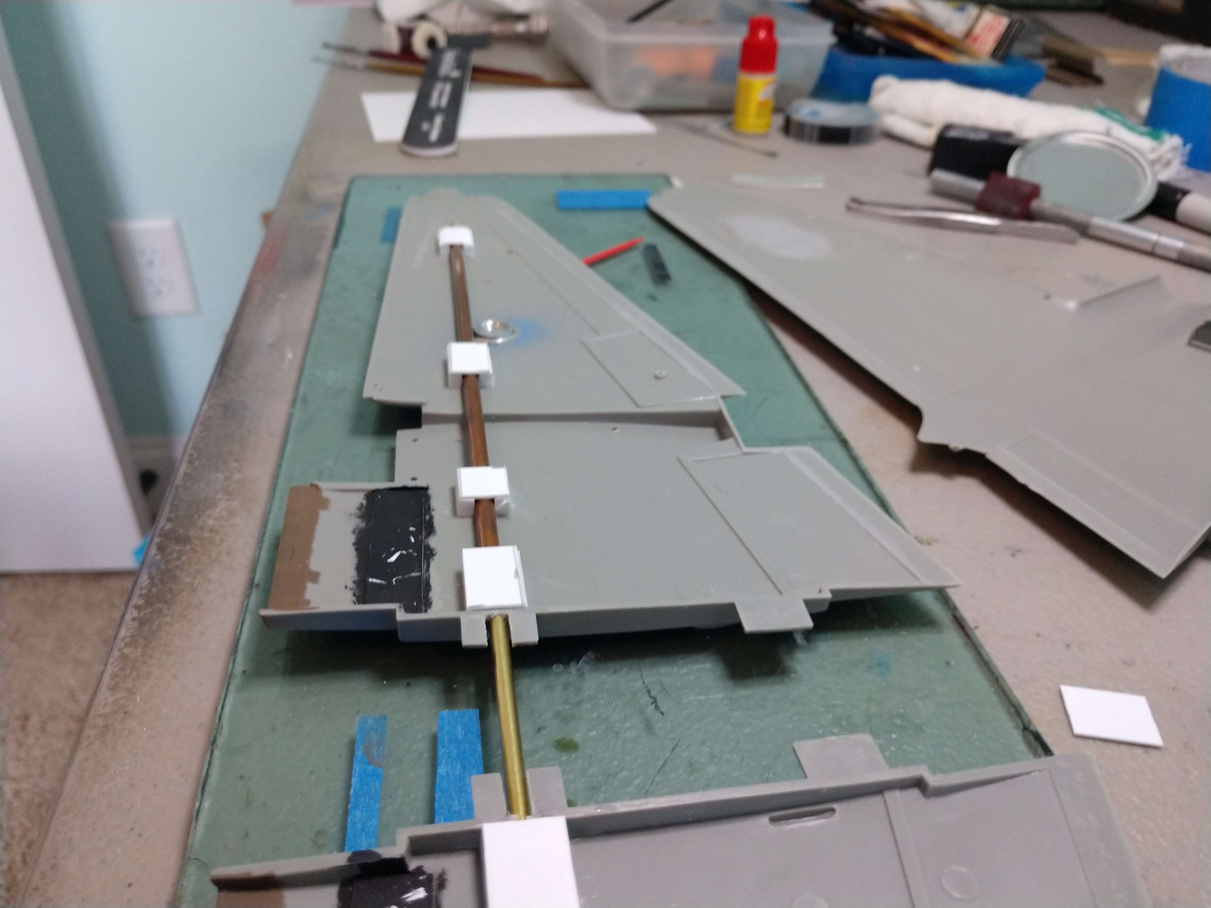
My solution was to use brass tubing attached to the lower wing halfs held in place with sheet plastic "saddles".
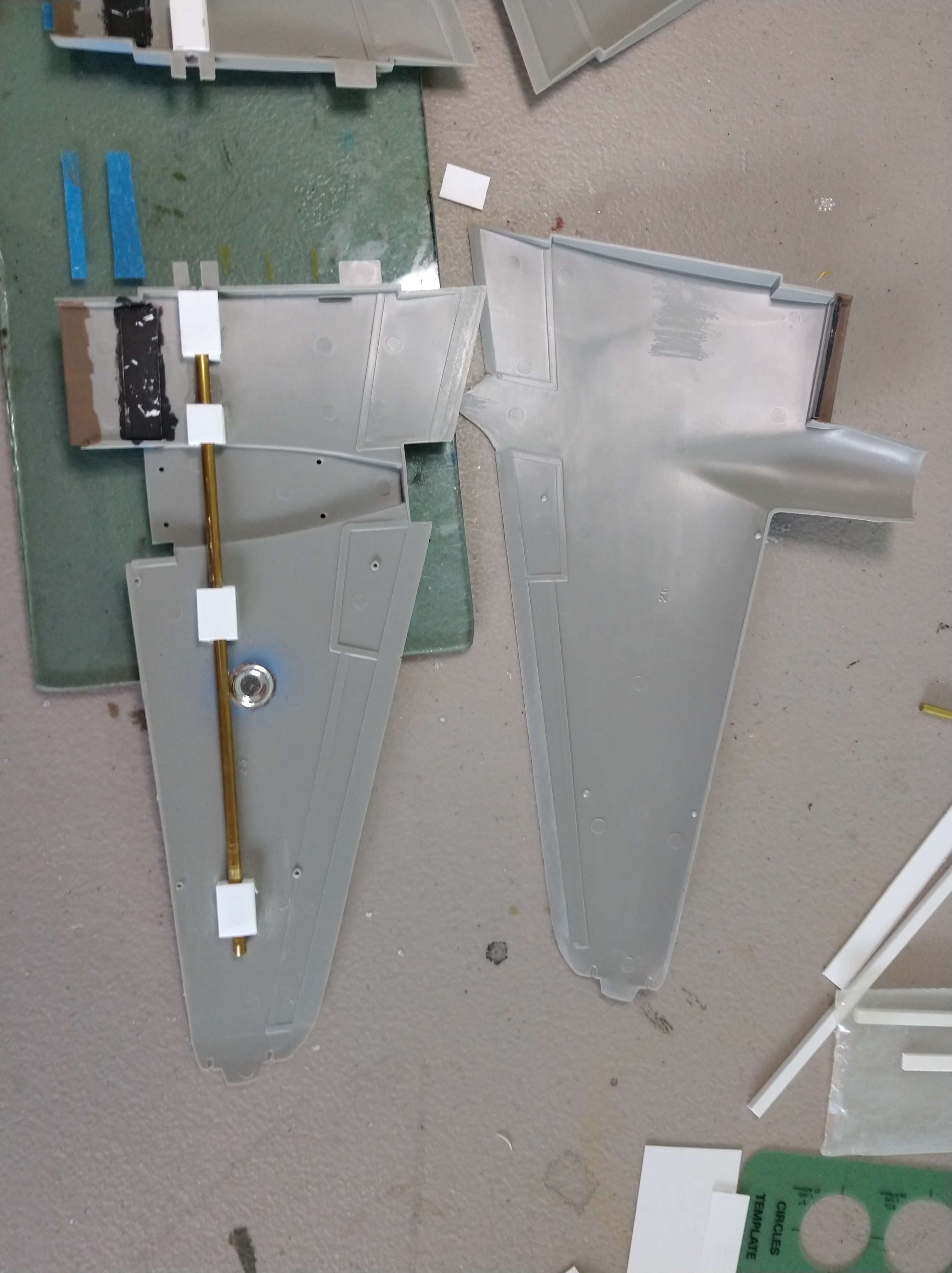
The port wing.
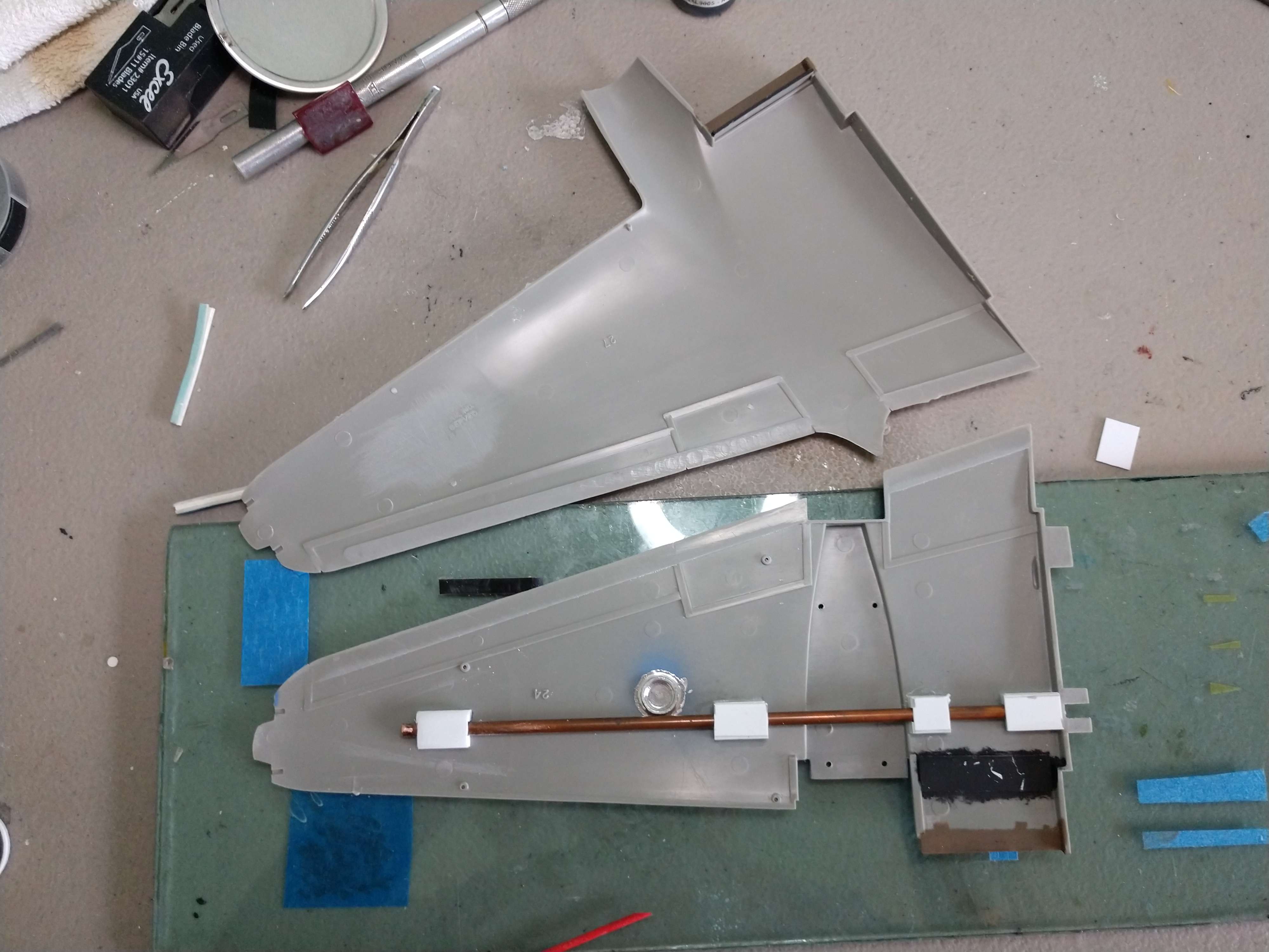
And the starboard.
The brass rod for each wing was only glued ,with CA, inboard of the nacelles. This would allow the brass rod to 'float" if I needed to adjust the any misalignment of outer wing panels.
The forward tab was notched and an opening was made for a brass rod that will be inserted into the tubing when the wings are attached to the fuselage. The rod will run nearly the length of the tubing in each wing. This is probably overkill but it will make for a solid join.

All in all an old school solution for an old school kit.
RD
-
On 1/15/2019 at 10:14 AM, rigor said:
Nice will be watching. Who makes the wheels. And where did you get them from
Thanks. I don't know who produced these wheels. I bought my Mosquito kits from a LSPer named James. [Sorry I don't remember his last name.] And the wheels came with those along with the Paragon sets.
-
On 1/15/2019 at 5:09 AM, Gerhard said:
OOP right?
Yes. Paragon resin is out of production.
-
On 1/7/2019 at 6:29 AM, Gerhard said:
Is that a cockpit upgrade I see on the left?
That is the Paragon FB MK VI conversion which does include a resin cockpit upgrade.
-
My entry in The Multi Engine GB is to going to be a Mosquito FB MK VI out of the Revell B MKVI with the help of some Paragon resin and a bit of scratch-building.
If all goes well it will be finished as HR399 OB-R of #45 Squadron.
- Daniel460, guitarlute101, Iain and 7 others
-
10
-
Awesome sheet.
- Jolly Roger and ziggyfoos
-
2
-
Unfortunately while passable, the Hasegawa nose is too slab-sided, lacking the proper horseshoe cross-section in favour of an inverted 'U; interpretation.
I don't have one to check against, but the recently issued Revell MkII is probably a better likeness, or the '60s vintage Mk I.
The latter has been reissued within the past few years as a Seafire Ib and can be found for buttons (I think I got 3 for £10 a few years ago).
Thanks for pointing out the alternatives. Using the RoG Spitfire MK. II is likely the best way to go for a Vc conversion.
-
For a 1/32nd scale Spitfire MK. Vc conversion I believe I would start with a RoG Spitfire MK.IX and a Hasegawa Spitfire MK. V. The Hasegawa kit would be primarily used to supply the nose section. To improve the economics of the build I would source at least the Hasegawa kit second hand.
RD.
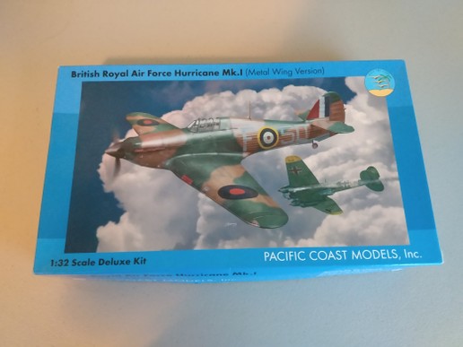
PCM Hawker Hurricane MK.1
in Works in Progress
Posted
Thanks Mike. That's what I achieved or close to it.
Richard