

DerekB
-
Posts
86 -
Joined
-
Last visited
Content Type
Profiles
Forums
Events
Posts posted by DerekB
-
-
Wonderful work Eric! I'm a big fan of 1920s/30s race planes. Imagine if this had flown! The pictures of this machine "floating" almost fully submerged are mind boggling!
-
Some small progress this evening from aboard my floating workshop...
Here's my "production line" for 1/32 scale Pratt & Whitney R-1340 Wasp engines. I need 2 complete geared engines (one for the Wirraway and one for a Ceres). On the left is the engine from the Kitty Hawk Texan kit, with all the cylinders molded integrally with the crank-case. I'm building this as a test-piece for colours and weathering. On the right are the two resin engines from Vector, with the 3D-printed gear reduction drive housings in front.
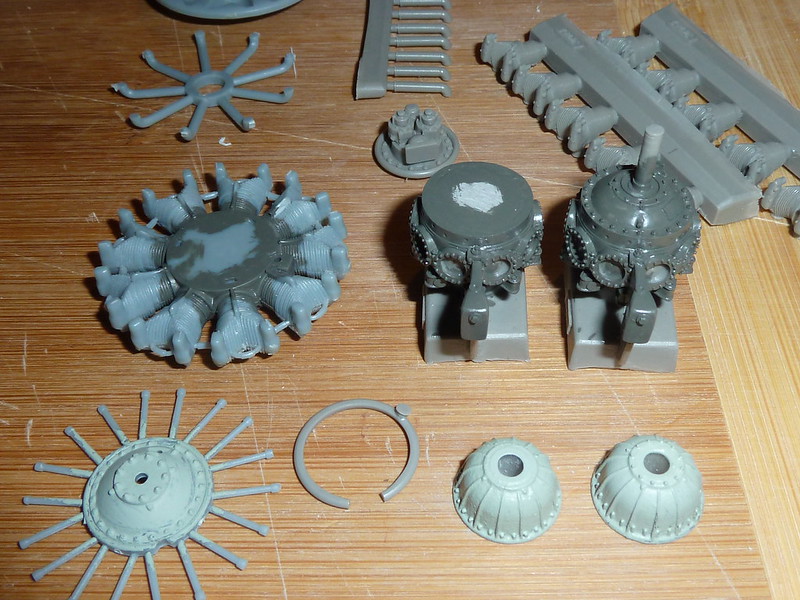
P1080572 by Derek Buckmaster, on Flickr
The 3D printed propeller hubs are back from Shapeways, and here is my "production line" for the Hamilton Standard 3D40 propellers:
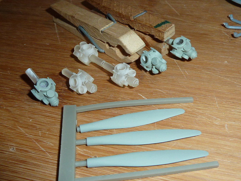
P1080573 by Derek Buckmaster, on Flickr
The nose of the Wirraway is quite different to the later Texan. I need to remove 9mm from the equipment bay to fit the new "dish-pan" at the rear of the cowl. Here I've marked the section to be removed:
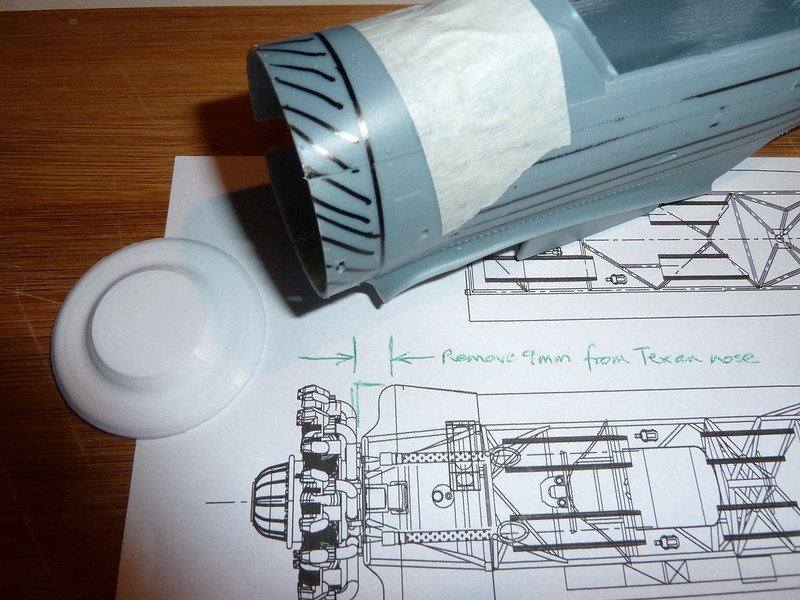
P1080574 by Derek Buckmaster, on Flickr
-
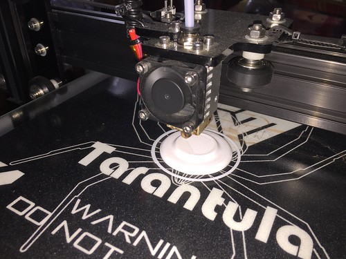
In addition to getting 3D printed parts from ShapeWays, I'm also experimenting with using my home-made Tevo Tarantula printer to print some parts at home. The Tarantula is a kit which you assemble yourself. I purchased it via a web vendor in China for about A$395.
Being a low-cost printer with only about 0.1mm resolution (layer thickness), I don't expect to be printing complicated parts (I'll save those for SW), but there are still a few less complex parts which should be doable with the Tarantula.
Here you see an almost-finished print of the engine "dish-pan" which covers the engine mount. This is a simple part with features that I'll scribe and glue into place.
IMG_7356 by Derek Buckmaster, on Flickr
-
Spent some time looking for better blades for the Hamilton Standard prop. The blades in the Kitty Hawk kit are far too thick, so I hunted around for some alternatives to better match the HS 6101A blade as shown in the photo below.
On the left (silver) is the Hamilton Standard prop from a Monogram Grumman Gulfhawk II kit. The shape is better than the Kitty Hawk kit prop, but the diameter is too small. In the middle (bluish grey) is the Kitty Hawk Texan kit prop, too thick and with an oddly tapered root section. On the right (brownish resin) is a Quickboost after-market resin blade from a Mk.Vb Spitfire. This was a Hamilton Standard propeller made under licence by deHavilland, and the blade shape correctly matches the 6101A drawing shape.
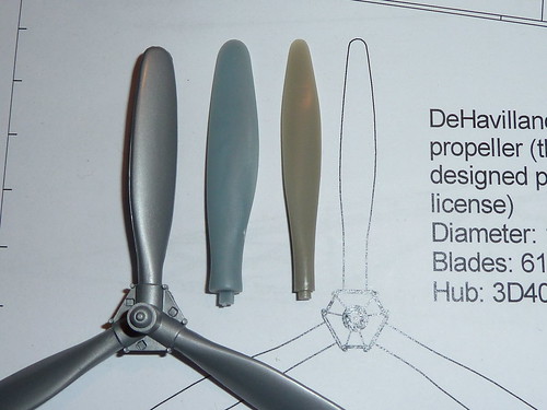
HS 6101A blades 2 by Derek Buckmaster, on Flickr
- sandokan, LSP_Kevin, Anthony in NZ and 2 others
-
 5
5
-
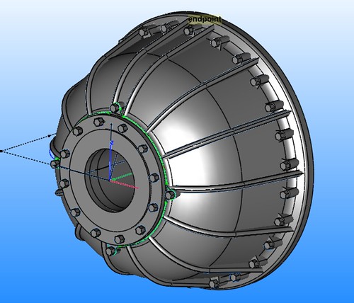
The next part to get the 3D printed treatment is the Hamilton Standard propeller hub.
I decided my attempts to kit-bash the 2-bladed Hamilton Standard 3D40 hub from the Texan kit into a 3-bladed 3D40 hub weren't going to satisfy me. After looking at the possibility of substituting a 3-bladed hub from a couple of different kits in my stash (Williams Brothers Seversky P-35 and Monogram Grumman G-22 Gulfhawk II use the same hub) I still wasn't happy, so I've drawn up the 3D40 hub in TurboCAD and sent the STL file off to Shapeways...
3D40 hub 02 by Derek Buckmaster, on Flickr
-
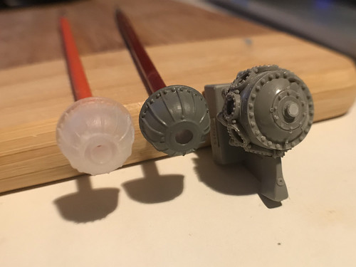
The 3D printed reduction drive housings have arrived from Shapeways, and I'm very pleased with the results...
 IMG_0311 by
Derek Buckmaster, on Flickr
On the left is an unpainted 3D printed housing, in the middle is a painted version and on the right is the crank-case for a non-geared Pratt & Whitney R-1340 Wasp engine from the Vector resin kit. The ribs and bosses on the 3D printed version look fabulous.
The 3D printed part will now be attached to the front of the resin crank-case, after removing the non-geared front housing detail.
The unpainted 3D printed part on the left also has nuts added (as shown in the 3D model above), but they're not visible in the unpainted state.
-
I've been looking at the Wasp R-1340 engine in the kit, and I'm thinking there must be some way to do better than this. The induction system on the back is all wrong, the spark plug leads are molded onto the front of the cylinders, and the fin detail on the cylinder heads is poor.
I picked up a Williams Brothers Gee Bee R, and that has a nicely detailed engine. So that's an option.
But then I picked up several Vector resin engines, and these are little works of art! So I'm planning to use one of these.
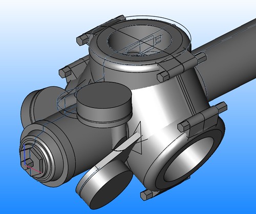
But in all three cases (the kit engine, the Gee Bee R engine, or the Vector engine) these are non-geared Wasps, so I need to do something about the reduction-drive housing on the front of the Wirraway's geared engine. This is a tapered housing, with lots of ribs and mounting bolts. Since I'm going to need several of these engines (at least one Wirraway, plus a Ceres) I decided to model the reduction drive housing in 3D CAD, and I've loaded this onto Shapeways and the first piece is being printed as I type.
Here's a look at the CAD model:
PW R-1340 reduction drive housing assy by Derek Buckmaster, on Flickr
If this works OK, I'll model up some more components to be used...
-
Spent a couple of hours in the reading room at the RAF Museum in Hendon (London) yesterday, so now I have copies of a full set of manuals and details for the Type B target towing winch, including the drawings below.
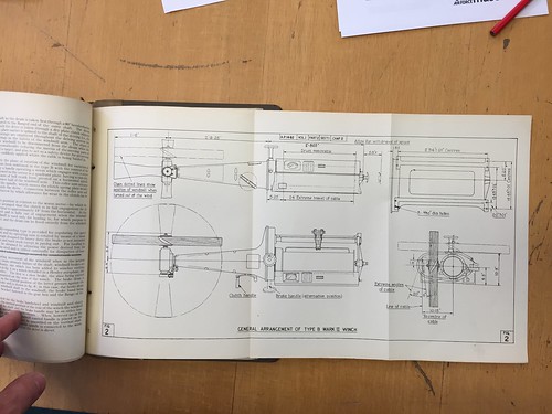
IMG_7249 by Derek Buckmaster, on Flickr
Muir's Southern Cross Mustangs book shows details of the external section of the towing winch, but nothing about the internal part. This collection gives me all the detail I need for the section of the winch inside the cockpit, so now I just need to scale this to 1/32 and start work on building it...
- Anthony in NZ, Kagemusha, KiwiZac and 5 others
-
8
-
14 hours ago, MARU5137 said:
Mr Buckmaster looks uncannily like Derk B from UK.

Maru, yes, I can understand the confusion!
Derek B from UK (not me) and Derek B from Australia (me)!
And to cap it off I'm on vacation in London for 2 weeks at the moment, so Derek B from Australia is in the UK!
-
-
Searching for references for this build, I contacted Geoff Goodall - luckily he is in the middle of updating his "Mustangs in Australia" web page, and he sent me a bunch of high resolution photos of VH-BOY. Fantastic.
You can see Geoff's Mustang page here: Mustangs in Australia He already has a couple of images of VH-BOY shown.
One of the photos is in colour and confirms the wheel wells were silver (not green) inside. Very helpful.
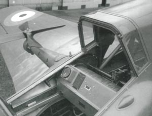
Still waiting for details of the Type B target towing winch from a contact in the UK, but an image from Spitfire Spares gives an indication of the appearance of the internal part of the winch:
- R Palimaka, sandokan, MikeC and 1 other
-
4
-
As I'm working on the electrical panels I needed to choose which specific aircraft at which specific time I'm going to model, since different versions of the Wirraway had different electrical boxes and wiring. So I've settled on A20-10, one of the earliest Wirraways produced, and the one currently held at the Australian National Aviation Museum in Moorabbin.
I plan to duplicate this aircraft as of late 1939 when she first joined No. 22 Squadron. She is shown early 1940 in the photo below:

This is also the colour scheme in which we restored her back in 2014 prior to her 75th birthday party, as shown in Brendan Cowan's photo below:

Here is yours truly hard at work applying fabric to one elevator during the restoration:
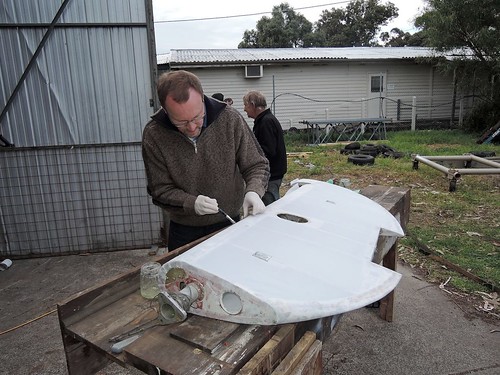
A20-10 Restoration 128 2014-08-08 (Jahne) by Derek Buckmaster, on Flickr
-
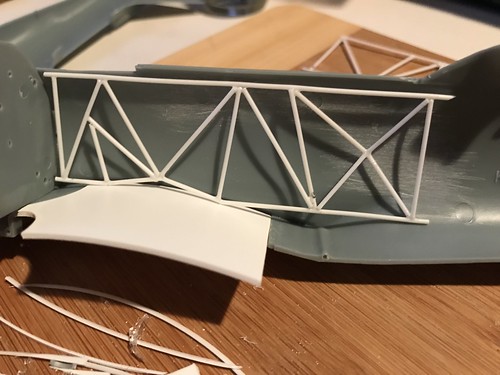
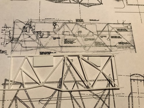
Now I'm trying to figure out how to install the internal frame...
The kit includes a "fake" flat cockpit floor (part D7) but in the real aircraft there is no floor, other than the top surface of the wing. So I've inserted a curved floor piece where the top surface of the wing should sit and now I'm looking at how to align the framework relative to this "floor". In the picture below the side frame is not quite in its final location (needs to move forward slightly so that the first upright tube is against the firewall).
USRSR7KgQ4uDg+xymO+Scw by Derek Buckmaster, on Flickr
The kit firewall is in the right location so I'll be using that after correcting the framework holes. I'll also be adding some framework on the internal wall, to simulate the interior of the fabric side panels on the Wirraway.
-
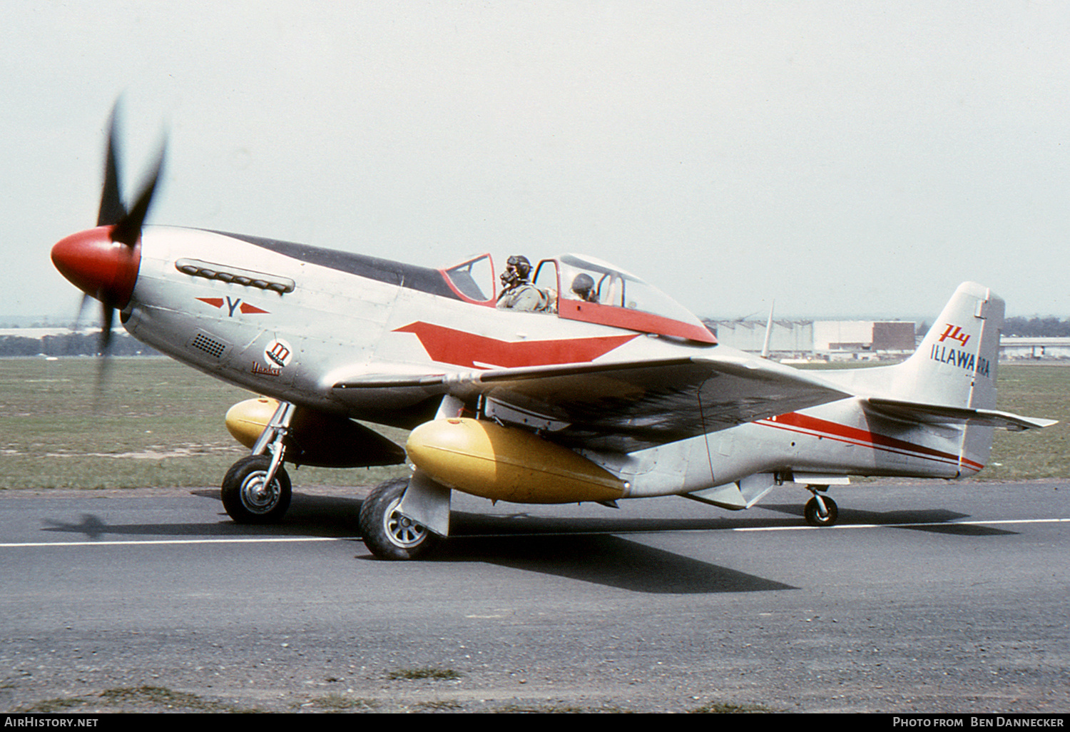
While searching for wheels for a CAC Ceres build I picked up a Hasegawa Mustang kit quite cheaply. I was originally just going to use the kit's wheels, but then I thought it might be fun to build the Mustang as A68-39, VH-BOY, known as "Yankee", one of the target-towing aircraft flown by Fawcett Aviation out of Bankstown in the 50's.
Fawcett's two Mustangs (VH-BOY "Yankee" and VH-BOZ "Miss Zulu") wore many colour schemes during their careers, but I quite like the early silver and red colours carried by "Yankee":
This build will be mostly OOB (a few small changes for the target towing gear), but since the interior of the Hasegawa kit is such a "blank canvas" I'm in dire need of pictures of the interior of a two-seat Mustang... can anyone help?
The fuselage fuel cell was removed and an observer's seat was installed behind the pilot, facing rearwards, to assist with target deployment and retrieval activities.Here's a shot of Fawcett's "Miss Zulu" in the same red speedbird colours (slightly different spinner) and showing the starboard-mounted propeller to power the target towing winch:

I have David Muir's excellent (but costly) Southern Cross Mustangs book for reference, but sadly no interior photos...
- MikeMaben, R Palimaka, coogrfan and 4 others
-
7
-
Starting work on the starboard electrical panels. The drawing at the top is an original CAC factory drawing, a great reference!
fullsizeoutput_bdc by Derek Buckmaster, on Flickr
-
-
I'm hoping when you regain your building space you'll buy another Texan so you can build a Ceres companion for the Wirraway!
Well Zac, the news is good. I already have two of these Kitty Hawk Texan kits!
Also a little more good news, I finally got my 3D printer software working, so I will soon be printing the gear housing for the geared Wasp engine used in the Wirraway and Ceres.
-
Things are moving slowly on this build, as I've temporarily lost my building space.
But on the good side, I've finally published my Ceres book, so if you're interested in scratch-building an Aussie crop-duster using the drawings in the book, check out the details on my website (link below)...
-
Hi Derek! I hope 1) your build is ongoing* and 2) you can join me in migrating away from Photobucket so I can see what you've done, as this is a tremendously exciting project!
*and the Ceres book, too! Looking forward to that one immensely.
Hi Zac, yes, this build is still going... it's going to be a slow one due to work commitments, trying to get my 3D printer up and running and working to get the Ceres book finished!
I've started using Flikr for the photos, and you can find the original album here: https://flic.kr/s/aHskYHUUDr
-
-
It's the carburetor air intake, IIRC.
Jessie, actually the vent is an outlet for oil cooler air. The oil cooler is mounted inside the cowling just near this vent.
The carb air intake is inside the cowl at the 6 o'clock position, with the duct running along the underside of the cowl leading to the carburettor.
Cheers,
Derek
-
A thin slice to remove but quite a big job to achieve, I think. Not to mention getting the dihedral back and ensuring the bolt line fairings still look ok. Id suggest making a dihedral jig before sawing the wings.
Hi SBH, yes, I'll be jigging the wing dihedral and trailing edge angle (straight). Luckily the bolt attach angle fairings are pre-molded into the centre section on this kit, so I won't be touching them. Biggest job on the outer wings will be new tips, ailerons and scribing new panel lines.
It's interesting to note that Wirraway wings (based on NA-33 contract but with many NA-26 and NA-36 part numbers) are identical to BC-1 wings (NA-36 contract).
-
Brilliant work on the frame! What glue did you use?
Jim
Nothing special Jim, just Revell Contacta Professional, with the long tube applicator. You'll notice I cut away the back of each joint to prevent the glue wicking along the jig, but it did just that on one joint, so there was a bit of "wrestling" to get the frame out. No breakages, so that was good. I have 2 workable frames now.
Derek
-
Watching this with great interest SBH, given that the BC-1 is almost a Wirraway (different rudder, engine and internal fit-out).
Derek

RAN A4G
in Works in Progress
Posted
very sweet work Chris. I was admiring two of these birds in the flesh at Nowra just 3 days ago.