

Biscuit Tin
-
Posts
14 -
Joined
-
Last visited
Reputation Activity
-

 Biscuit Tin got a reaction from KiwiZac in Tamiya 1/32 F-4J 'Silverkite 211'... with working features
Hello again,
Was coming near the end of the build, or so I thought. A few, final tweaks to the wiring and job done.
Here you can see where all the optic fibres and LED connections arrive at the nose - which is removable. I learned a while ago that anything electrical or mechanical - that cannot be reached when the model is 'closed up' - will, quite inevitably, fail. So the removable nose is the kind of penalty to be paid for this sort of project. The fit is not perfect... but then everything is a compromise.
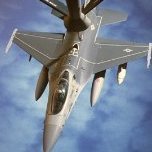
Then I had one of those 'how-the-hell-did-I-miss-that?' moments. You can see on the intake above that I have fitted the faired ECM antennas which I had thought were found on late-war Vietnam aircraft. Well, perhaps they were, but not the one I was doing. Which looked like this at the time: (source: wikimedia)
So they had to come off. Which left these patches either side.
I figured if I was really careful with masking I might, just be able to spray the patches and save the decals. Which I did on one side, but on the other the briefest overspray error with the primer got behind both masks and destroyed the star and bar and some of the non-slip walkway which was the kit supplied decal. Thus I had the classic modeller nightmare. An almost-finshed model needing serious spray repair, with all the harm that could do.
Well, here we are, a day or so later, and the repairs have been done and replacement stars and bars have been found for both sides. But the damage to the non-slip will have to stay because you can't sand decals and any attempt to do so would probably end up with me having to take the whole thing off - which essentially means starting the paint from scratch.
And, as a result of all this, I missed the fleeting, momentary patch of sun we've had these last several days so final pics will have to wait.
Next appearance will be in 'ready for inspection'.
-
Biscuit Tin got a reaction from KiwiZac in Tamiya 1/32 F-4J 'Silverkite 211'... with working features
Hello again,
Am waiting for the sun to come out to take some proper pictures - so I may be a while, this is England - but in the meanwhile here are some night shots for fun... a rainy night at Miramar.
The trailing edge formation lights blink... and I missed them. But I caught the big red flashing one on the tail. There are also lights under the intakes, you can just make tem out in the middle pic, and a dorsal one.
The model puts the dorsal light where the Air Force had it, not the Navy, so I moved it. There is interestingly a sort of molding of a small circle on the model where the light should go, so is not too hard to locate and I just blanked out the incorrect one.
-
 Biscuit Tin got a reaction from Lenny320 in Tamiya 1/32 F-4J 'Silverkite 211'... with working features
Once again, thanks for all the encouraging comments - and the helpful tips on what to do with flikr. Have stated using smugsmug which seems slightly easier to use.
As for being a watchmaker, well, I'd have much enjoyed that but am - dissapointingly no doubt - just a 'suit', in business. But was always fascinated by flight and have a couple of hundred hours or so as P1 in a variety of small, buzzy planes. What I would have done to have got behind the controls of an F4... (drifts off into daydream, again).
Am almost out of build pics. Here is an image of the the flap actuators. The main L.E flaps have rotating rod actuators which are OK but there just wasn't the 'head room' for these in the thin outer wings - so used small bell cranks. I realise - now of course - that I should have used push rods and bell cranks for all of them. That way I might have got the full range of motion of the real flaps. Live and learn, I suppose. The aluminium tube is to stiffen the push rods for the outer flaps
Next the Sidewinders. The kit supplied ones are the wrong model, as many have pointed put. It may not seem that big a deal but aircrew at the time would have been more than alert to the difference as D model was a big improvement on the B. The kit ones are Air Force missiles and would never have been fitted on the F4J.
You can get rather good aftermarket 'Ds' but I decided to re-model the kit ones. So shortened the noses and replaced the bodies with the correct length of aluminium tube to create these 'franken-rockets'. They may not be exactly right but are certainly 'righter'.
As I mentioned I needed to have opening canopies otherwise you can't get at the controls, which is kind of the point of the project. This choice, however, created fit problems because they are not designed to be used this way.
If you show them opened up the fit issue is not apparent and if you have them down you can tease them into the right place and 'trap' them with glue. But have them openable and they never look quite right! So I'm not thrilled with the result - but luckily the paint scheme goes some way to mask the fit issues.
Look carefully and you can see the hinge attachments and just about make out the canopy actuator piston which is chromed brass. I used the Eduard set for the mirrors and insides of the canopy sills.
Next up was the issue of how to power the model. The most popular and obvious method is to have a base with batteries. But that isn't much good for showing off the model's various features - you need to be able to handle it. Also, I don't like the mysterious wires coming up from the 'ground'.
I read, somewhere, that the large 600 gallon tanks could be disassembled and re-built so the idea occured to me to use this to house the batteries. This has the added benefit of concealing the connectors into the model. I also fitted four very small switches, just visible as small white blobs in the pylon: two for the engines - and one each for nav lights and cockpit lights.
The tank end, like the aircraft's nose cone, is held on with locating lugs and magnets. I bought a batch of about 50, tiny 2mm neodymium magnets and have used at least half in this kit!
Once again apologies for rubbish pics.
That is pretty much the end of my photos of the build. The next batch will be of the finished article.
-
 Biscuit Tin got a reaction from LSP_Kevin in Tamiya 1/32 F-4J 'Silverkite 211'... with working features
Hello again,
Was coming near the end of the build, or so I thought. A few, final tweaks to the wiring and job done.
Here you can see where all the optic fibres and LED connections arrive at the nose - which is removable. I learned a while ago that anything electrical or mechanical - that cannot be reached when the model is 'closed up' - will, quite inevitably, fail. So the removable nose is the kind of penalty to be paid for this sort of project. The fit is not perfect... but then everything is a compromise.
Then I had one of those 'how-the-hell-did-I-miss-that?' moments. You can see on the intake above that I have fitted the faired ECM antennas which I had thought were found on late-war Vietnam aircraft. Well, perhaps they were, but not the one I was doing. Which looked like this at the time: (source: wikimedia)
So they had to come off. Which left these patches either side.
I figured if I was really careful with masking I might, just be able to spray the patches and save the decals. Which I did on one side, but on the other the briefest overspray error with the primer got behind both masks and destroyed the star and bar and some of the non-slip walkway which was the kit supplied decal. Thus I had the classic modeller nightmare. An almost-finshed model needing serious spray repair, with all the harm that could do.
Well, here we are, a day or so later, and the repairs have been done and replacement stars and bars have been found for both sides. But the damage to the non-slip will have to stay because you can't sand decals and any attempt to do so would probably end up with me having to take the whole thing off - which essentially means starting the paint from scratch.
And, as a result of all this, I missed the fleeting, momentary patch of sun we've had these last several days so final pics will have to wait.
Next appearance will be in 'ready for inspection'.
-
 Biscuit Tin got a reaction from TorbenD in Tamiya 1/32 F-4J 'Silverkite 211'... with working features
Hello again,
Am waiting for the sun to come out to take some proper pictures - so I may be a while, this is England - but in the meanwhile here are some night shots for fun... a rainy night at Miramar.
The trailing edge formation lights blink... and I missed them. But I caught the big red flashing one on the tail. There are also lights under the intakes, you can just make tem out in the middle pic, and a dorsal one.
The model puts the dorsal light where the Air Force had it, not the Navy, so I moved it. There is interestingly a sort of molding of a small circle on the model where the light should go, so is not too hard to locate and I just blanked out the incorrect one.
-
Biscuit Tin got a reaction from TorbenD in Tamiya 1/32 F-4J 'Silverkite 211'... with working features
Once again, thanks for all the encouraging comments - and the helpful tips on what to do with flikr. Have stated using smugsmug which seems slightly easier to use.
As for being a watchmaker, well, I'd have much enjoyed that but am - dissapointingly no doubt - just a 'suit', in business. But was always fascinated by flight and have a couple of hundred hours or so as P1 in a variety of small, buzzy planes. What I would have done to have got behind the controls of an F4... (drifts off into daydream, again).
Am almost out of build pics. Here is an image of the the flap actuators. The main L.E flaps have rotating rod actuators which are OK but there just wasn't the 'head room' for these in the thin outer wings - so used small bell cranks. I realise - now of course - that I should have used push rods and bell cranks for all of them. That way I might have got the full range of motion of the real flaps. Live and learn, I suppose. The aluminium tube is to stiffen the push rods for the outer flaps
Next the Sidewinders. The kit supplied ones are the wrong model, as many have pointed put. It may not seem that big a deal but aircrew at the time would have been more than alert to the difference as D model was a big improvement on the B. The kit ones are Air Force missiles and would never have been fitted on the F4J.
You can get rather good aftermarket 'Ds' but I decided to re-model the kit ones. So shortened the noses and replaced the bodies with the correct length of aluminium tube to create these 'franken-rockets'. They may not be exactly right but are certainly 'righter'.
As I mentioned I needed to have opening canopies otherwise you can't get at the controls, which is kind of the point of the project. This choice, however, created fit problems because they are not designed to be used this way.
If you show them opened up the fit issue is not apparent and if you have them down you can tease them into the right place and 'trap' them with glue. But have them openable and they never look quite right! So I'm not thrilled with the result - but luckily the paint scheme goes some way to mask the fit issues.
Look carefully and you can see the hinge attachments and just about make out the canopy actuator piston which is chromed brass. I used the Eduard set for the mirrors and insides of the canopy sills.
Next up was the issue of how to power the model. The most popular and obvious method is to have a base with batteries. But that isn't much good for showing off the model's various features - you need to be able to handle it. Also, I don't like the mysterious wires coming up from the 'ground'.
I read, somewhere, that the large 600 gallon tanks could be disassembled and re-built so the idea occured to me to use this to house the batteries. This has the added benefit of concealing the connectors into the model. I also fitted four very small switches, just visible as small white blobs in the pylon: two for the engines - and one each for nav lights and cockpit lights.
The tank end, like the aircraft's nose cone, is held on with locating lugs and magnets. I bought a batch of about 50, tiny 2mm neodymium magnets and have used at least half in this kit!
Once again apologies for rubbish pics.
That is pretty much the end of my photos of the build. The next batch will be of the finished article.
-
 Biscuit Tin got a reaction from MikeMaben in Tamiya 1/32 F-4J 'Silverkite 211'... with working features
Hello again,
Am waiting for the sun to come out to take some proper pictures - so I may be a while, this is England - but in the meanwhile here are some night shots for fun... a rainy night at Miramar.
The trailing edge formation lights blink... and I missed them. But I caught the big red flashing one on the tail. There are also lights under the intakes, you can just make tem out in the middle pic, and a dorsal one.
The model puts the dorsal light where the Air Force had it, not the Navy, so I moved it. There is interestingly a sort of molding of a small circle on the model where the light should go, so is not too hard to locate and I just blanked out the incorrect one.
-
Biscuit Tin got a reaction from LSP_Kevin in Tamiya 1/32 F-4J 'Silverkite 211'... with working features
Hello again,
Am waiting for the sun to come out to take some proper pictures - so I may be a while, this is England - but in the meanwhile here are some night shots for fun... a rainy night at Miramar.
The trailing edge formation lights blink... and I missed them. But I caught the big red flashing one on the tail. There are also lights under the intakes, you can just make tem out in the middle pic, and a dorsal one.
The model puts the dorsal light where the Air Force had it, not the Navy, so I moved it. There is interestingly a sort of molding of a small circle on the model where the light should go, so is not too hard to locate and I just blanked out the incorrect one.
-
 Biscuit Tin got a reaction from Marcel111 in Tamiya 1/32 F-4J 'Silverkite 211'... with working features
Flight control surfaces were quite a challenge. A cursory glance at the F4 (and indeed many other aircraft of the period) shows it to be covered in very tiny 'piano hinges' which are used for pretty much every moveable surface. It is possible to make other discrete hinge types as a subsititute, but they simply don't look right and most are very weak.
So, in the end, I designed photoetched hinge strip and assembled them myself. They were fiddly to make but resulted in a surprisingly strong and realistic looking hinges. They need to be sort of bent at 90 degrees to fit into the slots cut where the plastic molding of them was. Here you can also see the L.E flaps, hinges - and actuators which were made using a sort of bell crank type mechanism.
Here are the trailing edge flaps and the flaperon hinge. All the flaps, leading and trailing, are mechanically linked to the arrester hook and deploy when the hook is lowered.
The funny crutch shaped thing in the wheel well is not found on the real thing and is intedned to push the weel back into full detente on the suspension spring. Without the wheel being fully retracted like this it will not fit in the well and the inner door cannot close - it's the same on the real thing. On the real thing, however, there is a lever on the wheel mount that is pulled up mechnically, as the wheel comes up, to ensure it is fully in before being retracted. Given the size of the componants involved this would be almost impossible to model at this scale - unless working in steel.
The flaperons are actuated by a sort of semi-realistic rendition of the hydraulic jack that powers them. On the real thing, this jack can itself can be moved for and aft hydraulicly, hence allowing the flaperons to function as flaps and aileron simultaneously.
The flaperons were spring loaded to somthing close to the horizontal - but only just as the control forces are not strong.
The flat straplike thing at the outboard end of the main gear was intended to work as a gear down lock with the hole locating to a small pin in the head of the landing gear piston case. This did not work well as it was to close to the centre of pivot and so the gear still wobbled. In the end I have used a sort of removable piston restraint to lock them - like the real thing, when left for any time.
In the pic above you can see that the wing was getting pretty busy before being closed up and it was a fiddle to keep optic fibres, springs and actuators from interfering with each other.
All this cutting away of the wing left it really weak and liable to almost Spitfire-like dihedral under load, so I added a first then second wing spar in brass. Here's the second, afterward of the two. It attaches to the aft wall of the wheel wells.
That's it for now.
-
Biscuit Tin got a reaction from Marcel111 in Tamiya 1/32 F-4J 'Silverkite 211'... with working features
Hello all,
I'm new here and wanted to share a recent project, one that is nine tenths finshed - but may benefit from being shown from the beginning.
I've loved Phantoms since I was a child - their taut, 'business-like' appearance and reputation for power and speed always appealed. Later, as a young(er) adult I was also fortunate enough to see, courtesy of Her Majesty, an RAF version engage ground targets with its vulcan gun. Not something to forget in a hurry.
Anyhow, my build is a US Navy version, namely the VF-92 aircraft flown by Curt Dose and Jim McDevitt in their successful raid on Kep airfield in 1972. It is a fascinating story - engagingly told by the pilot himself here . I also like the white noses of that squadron and the 'I-don't-give-a-damn-whether-you-can-see-me-or-not' attitude of the overall schemes of that period.
My version is a bit different from most models of this or similar subjects, however. I set out to build-in the following features: working flight controls, retractable undercart, wheel suspension, working lights, illuminated cockpit and gunsight, openable canopy, deployable flaps and arrester hook and spinning compressor blades. It is, as you can imagine, quite a lot to pack into a model, even of this size. And how well it works, well, you'll be able to judge for yourselves.
Why? Well I had some success doing some of this with a 1:24 Trumpeter Hurricane a couple of years back and fancied the challenge of mimicking the very different operation of a jet's controls - more on that later. But generally, I like the idea of a model being able to show some of the life of the real thing, so the model can sort of explain itself in other words. Some other boat and vehicle projects I've done in the same vein can be seen here if anyone is interested.
Where to begin? I started with the wheels, imagining - wrongly - that these would be straightforward, especially after the nightmare complexity of the Hurricane. But, in reality F4s have, like a lot of naval aircraft, quite complex wheel geometry - not apparent when you look at them - to say nothing of the linkages between the landing leg itself and the secondary doors. So I had to make each of the main struts in brass, and adjustable in all axes, so I could firm up on the motion when I had worked out what it should be.
You can just about make out the screw that will tighten the landing gear when the correct angle was worked out.
Next discovery was that the gear struts themselves are almost certainly not quite in the right place on the model. No matter how I tried to work it, the wheels and doors could not function properly, this close to the fuselage. And indeed if you compare the wheel doors to available drawings, the secondary door (the little outboard gear door on each main wheel) is larger in real life than on the model. I concluded the wheels must be about 2 or 3mm too far inboard.
I also wanted the wheels to turn freely so fitted bearings. You can more or less see that the strut itself looks like real chrome... and that is because it is. I found this remarkable - as in easy to use - kit from the US that allows you to chrome up (well polished) brass tube and I made a lot of use of it on this project.
The oleo struts are supported by small springs in the cylinder.
The slot in the oleo is to keep the wheel pointing in one direction as it slides up and down past a locating pin.
The nose gear works the same way. You can see I had to replace the plastic 'scissors' as the orignals would break quickly when the gear moves up and down.
Here you can see one of the main gear struts in the retracted position. The scissors are from the Eduard set and are useful for this kind of project, as long as the pieces are soldered rather than glued.
You can just about make out what turned out to be the solution to the geometry issue. The main hinge is angled downward in the forward direction and slightly outward from the fuselage in the horizontal axis. This general arrangement was found by experiment - and confirmed by photographs.
It is also worth mentioning that either the model wing section is too shallow or the gear too deep but, as supplied, they cannot possibly retract and I had to narrow the tires and wheels by about 1.5mm. Also, there is a sort of connecting piece across the well that is severely in error and prevents retraction, whatever the shape or thickness of the gear. That had to go. But because no one will see in the wheel well I have not replaced it with a corrected part.
Hope this is of interest.
Next up, engines and fans...
-
 Biscuit Tin got a reaction from Rainer Hoffmann in Tamiya 1/32 F-4J 'Silverkite 211'... with working features
Flight control surfaces were quite a challenge. A cursory glance at the F4 (and indeed many other aircraft of the period) shows it to be covered in very tiny 'piano hinges' which are used for pretty much every moveable surface. It is possible to make other discrete hinge types as a subsititute, but they simply don't look right and most are very weak.
So, in the end, I designed photoetched hinge strip and assembled them myself. They were fiddly to make but resulted in a surprisingly strong and realistic looking hinges. They need to be sort of bent at 90 degrees to fit into the slots cut where the plastic molding of them was. Here you can also see the L.E flaps, hinges - and actuators which were made using a sort of bell crank type mechanism.
Here are the trailing edge flaps and the flaperon hinge. All the flaps, leading and trailing, are mechanically linked to the arrester hook and deploy when the hook is lowered.
The funny crutch shaped thing in the wheel well is not found on the real thing and is intedned to push the weel back into full detente on the suspension spring. Without the wheel being fully retracted like this it will not fit in the well and the inner door cannot close - it's the same on the real thing. On the real thing, however, there is a lever on the wheel mount that is pulled up mechnically, as the wheel comes up, to ensure it is fully in before being retracted. Given the size of the componants involved this would be almost impossible to model at this scale - unless working in steel.
The flaperons are actuated by a sort of semi-realistic rendition of the hydraulic jack that powers them. On the real thing, this jack can itself can be moved for and aft hydraulicly, hence allowing the flaperons to function as flaps and aileron simultaneously.
The flaperons were spring loaded to somthing close to the horizontal - but only just as the control forces are not strong.
The flat straplike thing at the outboard end of the main gear was intended to work as a gear down lock with the hole locating to a small pin in the head of the landing gear piston case. This did not work well as it was to close to the centre of pivot and so the gear still wobbled. In the end I have used a sort of removable piston restraint to lock them - like the real thing, when left for any time.
In the pic above you can see that the wing was getting pretty busy before being closed up and it was a fiddle to keep optic fibres, springs and actuators from interfering with each other.
All this cutting away of the wing left it really weak and liable to almost Spitfire-like dihedral under load, so I added a first then second wing spar in brass. Here's the second, afterward of the two. It attaches to the aft wall of the wheel wells.
That's it for now.
-
 Biscuit Tin got a reaction from Troy Molitor in Tamiya 1/32 F-4J 'Silverkite 211'... with working features
Hello again,
Am waiting for the sun to come out to take some proper pictures - so I may be a while, this is England - but in the meanwhile here are some night shots for fun... a rainy night at Miramar.
The trailing edge formation lights blink... and I missed them. But I caught the big red flashing one on the tail. There are also lights under the intakes, you can just make tem out in the middle pic, and a dorsal one.
The model puts the dorsal light where the Air Force had it, not the Navy, so I moved it. There is interestingly a sort of molding of a small circle on the model where the light should go, so is not too hard to locate and I just blanked out the incorrect one.
-
 Biscuit Tin got a reaction from Shawn M in Tamiya 1/32 F-4J 'Silverkite 211'... with working features
Hello again,
Am waiting for the sun to come out to take some proper pictures - so I may be a while, this is England - but in the meanwhile here are some night shots for fun... a rainy night at Miramar.
The trailing edge formation lights blink... and I missed them. But I caught the big red flashing one on the tail. There are also lights under the intakes, you can just make tem out in the middle pic, and a dorsal one.
The model puts the dorsal light where the Air Force had it, not the Navy, so I moved it. There is interestingly a sort of molding of a small circle on the model where the light should go, so is not too hard to locate and I just blanked out the incorrect one.
-
 Biscuit Tin got a reaction from NavyF4s in Tamiya 1/32 F-4J 'Silverkite 211'... with working features
Once again, thanks for all the encouraging comments - and the helpful tips on what to do with flikr. Have stated using smugsmug which seems slightly easier to use.
As for being a watchmaker, well, I'd have much enjoyed that but am - dissapointingly no doubt - just a 'suit', in business. But was always fascinated by flight and have a couple of hundred hours or so as P1 in a variety of small, buzzy planes. What I would have done to have got behind the controls of an F4... (drifts off into daydream, again).
Am almost out of build pics. Here is an image of the the flap actuators. The main L.E flaps have rotating rod actuators which are OK but there just wasn't the 'head room' for these in the thin outer wings - so used small bell cranks. I realise - now of course - that I should have used push rods and bell cranks for all of them. That way I might have got the full range of motion of the real flaps. Live and learn, I suppose. The aluminium tube is to stiffen the push rods for the outer flaps
Next the Sidewinders. The kit supplied ones are the wrong model, as many have pointed put. It may not seem that big a deal but aircrew at the time would have been more than alert to the difference as D model was a big improvement on the B. The kit ones are Air Force missiles and would never have been fitted on the F4J.
You can get rather good aftermarket 'Ds' but I decided to re-model the kit ones. So shortened the noses and replaced the bodies with the correct length of aluminium tube to create these 'franken-rockets'. They may not be exactly right but are certainly 'righter'.
As I mentioned I needed to have opening canopies otherwise you can't get at the controls, which is kind of the point of the project. This choice, however, created fit problems because they are not designed to be used this way.
If you show them opened up the fit issue is not apparent and if you have them down you can tease them into the right place and 'trap' them with glue. But have them openable and they never look quite right! So I'm not thrilled with the result - but luckily the paint scheme goes some way to mask the fit issues.
Look carefully and you can see the hinge attachments and just about make out the canopy actuator piston which is chromed brass. I used the Eduard set for the mirrors and insides of the canopy sills.
Next up was the issue of how to power the model. The most popular and obvious method is to have a base with batteries. But that isn't much good for showing off the model's various features - you need to be able to handle it. Also, I don't like the mysterious wires coming up from the 'ground'.
I read, somewhere, that the large 600 gallon tanks could be disassembled and re-built so the idea occured to me to use this to house the batteries. This has the added benefit of concealing the connectors into the model. I also fitted four very small switches, just visible as small white blobs in the pylon: two for the engines - and one each for nav lights and cockpit lights.
The tank end, like the aircraft's nose cone, is held on with locating lugs and magnets. I bought a batch of about 50, tiny 2mm neodymium magnets and have used at least half in this kit!
Once again apologies for rubbish pics.
That is pretty much the end of my photos of the build. The next batch will be of the finished article.
-
.thumb.jpg.dcaaac7ca187fee833430d28711f104e.jpg) Biscuit Tin got a reaction from Harrison90 in Tamiya 1/32 F-4J 'Silverkite 211'... with working features
Biscuit Tin got a reaction from Harrison90 in Tamiya 1/32 F-4J 'Silverkite 211'... with working features
Once again, thanks for all the encouraging comments - and the helpful tips on what to do with flikr. Have stated using smugsmug which seems slightly easier to use.
As for being a watchmaker, well, I'd have much enjoyed that but am - dissapointingly no doubt - just a 'suit', in business. But was always fascinated by flight and have a couple of hundred hours or so as P1 in a variety of small, buzzy planes. What I would have done to have got behind the controls of an F4... (drifts off into daydream, again).
Am almost out of build pics. Here is an image of the the flap actuators. The main L.E flaps have rotating rod actuators which are OK but there just wasn't the 'head room' for these in the thin outer wings - so used small bell cranks. I realise - now of course - that I should have used push rods and bell cranks for all of them. That way I might have got the full range of motion of the real flaps. Live and learn, I suppose. The aluminium tube is to stiffen the push rods for the outer flaps
Next the Sidewinders. The kit supplied ones are the wrong model, as many have pointed put. It may not seem that big a deal but aircrew at the time would have been more than alert to the difference as D model was a big improvement on the B. The kit ones are Air Force missiles and would never have been fitted on the F4J.
You can get rather good aftermarket 'Ds' but I decided to re-model the kit ones. So shortened the noses and replaced the bodies with the correct length of aluminium tube to create these 'franken-rockets'. They may not be exactly right but are certainly 'righter'.
As I mentioned I needed to have opening canopies otherwise you can't get at the controls, which is kind of the point of the project. This choice, however, created fit problems because they are not designed to be used this way.
If you show them opened up the fit issue is not apparent and if you have them down you can tease them into the right place and 'trap' them with glue. But have them openable and they never look quite right! So I'm not thrilled with the result - but luckily the paint scheme goes some way to mask the fit issues.
Look carefully and you can see the hinge attachments and just about make out the canopy actuator piston which is chromed brass. I used the Eduard set for the mirrors and insides of the canopy sills.
Next up was the issue of how to power the model. The most popular and obvious method is to have a base with batteries. But that isn't much good for showing off the model's various features - you need to be able to handle it. Also, I don't like the mysterious wires coming up from the 'ground'.
I read, somewhere, that the large 600 gallon tanks could be disassembled and re-built so the idea occured to me to use this to house the batteries. This has the added benefit of concealing the connectors into the model. I also fitted four very small switches, just visible as small white blobs in the pylon: two for the engines - and one each for nav lights and cockpit lights.
The tank end, like the aircraft's nose cone, is held on with locating lugs and magnets. I bought a batch of about 50, tiny 2mm neodymium magnets and have used at least half in this kit!
Once again apologies for rubbish pics.
That is pretty much the end of my photos of the build. The next batch will be of the finished article.
-
Biscuit Tin got a reaction from KiwiZac in Tamiya 1/32 F-4J 'Silverkite 211'... with working features
Once again, thanks for all the encouraging comments - and the helpful tips on what to do with flikr. Have stated using smugsmug which seems slightly easier to use.
As for being a watchmaker, well, I'd have much enjoyed that but am - dissapointingly no doubt - just a 'suit', in business. But was always fascinated by flight and have a couple of hundred hours or so as P1 in a variety of small, buzzy planes. What I would have done to have got behind the controls of an F4... (drifts off into daydream, again).
Am almost out of build pics. Here is an image of the the flap actuators. The main L.E flaps have rotating rod actuators which are OK but there just wasn't the 'head room' for these in the thin outer wings - so used small bell cranks. I realise - now of course - that I should have used push rods and bell cranks for all of them. That way I might have got the full range of motion of the real flaps. Live and learn, I suppose. The aluminium tube is to stiffen the push rods for the outer flaps
Next the Sidewinders. The kit supplied ones are the wrong model, as many have pointed put. It may not seem that big a deal but aircrew at the time would have been more than alert to the difference as D model was a big improvement on the B. The kit ones are Air Force missiles and would never have been fitted on the F4J.
You can get rather good aftermarket 'Ds' but I decided to re-model the kit ones. So shortened the noses and replaced the bodies with the correct length of aluminium tube to create these 'franken-rockets'. They may not be exactly right but are certainly 'righter'.
As I mentioned I needed to have opening canopies otherwise you can't get at the controls, which is kind of the point of the project. This choice, however, created fit problems because they are not designed to be used this way.
If you show them opened up the fit issue is not apparent and if you have them down you can tease them into the right place and 'trap' them with glue. But have them openable and they never look quite right! So I'm not thrilled with the result - but luckily the paint scheme goes some way to mask the fit issues.
Look carefully and you can see the hinge attachments and just about make out the canopy actuator piston which is chromed brass. I used the Eduard set for the mirrors and insides of the canopy sills.
Next up was the issue of how to power the model. The most popular and obvious method is to have a base with batteries. But that isn't much good for showing off the model's various features - you need to be able to handle it. Also, I don't like the mysterious wires coming up from the 'ground'.
I read, somewhere, that the large 600 gallon tanks could be disassembled and re-built so the idea occured to me to use this to house the batteries. This has the added benefit of concealing the connectors into the model. I also fitted four very small switches, just visible as small white blobs in the pylon: two for the engines - and one each for nav lights and cockpit lights.
The tank end, like the aircraft's nose cone, is held on with locating lugs and magnets. I bought a batch of about 50, tiny 2mm neodymium magnets and have used at least half in this kit!
Once again apologies for rubbish pics.
That is pretty much the end of my photos of the build. The next batch will be of the finished article.
-
Biscuit Tin got a reaction from Shawn M in Tamiya 1/32 F-4J 'Silverkite 211'... with working features
Once again, thanks for all the encouraging comments - and the helpful tips on what to do with flikr. Have stated using smugsmug which seems slightly easier to use.
As for being a watchmaker, well, I'd have much enjoyed that but am - dissapointingly no doubt - just a 'suit', in business. But was always fascinated by flight and have a couple of hundred hours or so as P1 in a variety of small, buzzy planes. What I would have done to have got behind the controls of an F4... (drifts off into daydream, again).
Am almost out of build pics. Here is an image of the the flap actuators. The main L.E flaps have rotating rod actuators which are OK but there just wasn't the 'head room' for these in the thin outer wings - so used small bell cranks. I realise - now of course - that I should have used push rods and bell cranks for all of them. That way I might have got the full range of motion of the real flaps. Live and learn, I suppose. The aluminium tube is to stiffen the push rods for the outer flaps
Next the Sidewinders. The kit supplied ones are the wrong model, as many have pointed put. It may not seem that big a deal but aircrew at the time would have been more than alert to the difference as D model was a big improvement on the B. The kit ones are Air Force missiles and would never have been fitted on the F4J.
You can get rather good aftermarket 'Ds' but I decided to re-model the kit ones. So shortened the noses and replaced the bodies with the correct length of aluminium tube to create these 'franken-rockets'. They may not be exactly right but are certainly 'righter'.
As I mentioned I needed to have opening canopies otherwise you can't get at the controls, which is kind of the point of the project. This choice, however, created fit problems because they are not designed to be used this way.
If you show them opened up the fit issue is not apparent and if you have them down you can tease them into the right place and 'trap' them with glue. But have them openable and they never look quite right! So I'm not thrilled with the result - but luckily the paint scheme goes some way to mask the fit issues.
Look carefully and you can see the hinge attachments and just about make out the canopy actuator piston which is chromed brass. I used the Eduard set for the mirrors and insides of the canopy sills.
Next up was the issue of how to power the model. The most popular and obvious method is to have a base with batteries. But that isn't much good for showing off the model's various features - you need to be able to handle it. Also, I don't like the mysterious wires coming up from the 'ground'.
I read, somewhere, that the large 600 gallon tanks could be disassembled and re-built so the idea occured to me to use this to house the batteries. This has the added benefit of concealing the connectors into the model. I also fitted four very small switches, just visible as small white blobs in the pylon: two for the engines - and one each for nav lights and cockpit lights.
The tank end, like the aircraft's nose cone, is held on with locating lugs and magnets. I bought a batch of about 50, tiny 2mm neodymium magnets and have used at least half in this kit!
Once again apologies for rubbish pics.
That is pretty much the end of my photos of the build. The next batch will be of the finished article.
-
 Biscuit Tin got a reaction from patricksparks in Tamiya 1/32 F-4J 'Silverkite 211'... with working features
Once again, thanks for all the encouraging comments - and the helpful tips on what to do with flikr. Have stated using smugsmug which seems slightly easier to use.
As for being a watchmaker, well, I'd have much enjoyed that but am - dissapointingly no doubt - just a 'suit', in business. But was always fascinated by flight and have a couple of hundred hours or so as P1 in a variety of small, buzzy planes. What I would have done to have got behind the controls of an F4... (drifts off into daydream, again).
Am almost out of build pics. Here is an image of the the flap actuators. The main L.E flaps have rotating rod actuators which are OK but there just wasn't the 'head room' for these in the thin outer wings - so used small bell cranks. I realise - now of course - that I should have used push rods and bell cranks for all of them. That way I might have got the full range of motion of the real flaps. Live and learn, I suppose. The aluminium tube is to stiffen the push rods for the outer flaps
Next the Sidewinders. The kit supplied ones are the wrong model, as many have pointed put. It may not seem that big a deal but aircrew at the time would have been more than alert to the difference as D model was a big improvement on the B. The kit ones are Air Force missiles and would never have been fitted on the F4J.
You can get rather good aftermarket 'Ds' but I decided to re-model the kit ones. So shortened the noses and replaced the bodies with the correct length of aluminium tube to create these 'franken-rockets'. They may not be exactly right but are certainly 'righter'.
As I mentioned I needed to have opening canopies otherwise you can't get at the controls, which is kind of the point of the project. This choice, however, created fit problems because they are not designed to be used this way.
If you show them opened up the fit issue is not apparent and if you have them down you can tease them into the right place and 'trap' them with glue. But have them openable and they never look quite right! So I'm not thrilled with the result - but luckily the paint scheme goes some way to mask the fit issues.
Look carefully and you can see the hinge attachments and just about make out the canopy actuator piston which is chromed brass. I used the Eduard set for the mirrors and insides of the canopy sills.
Next up was the issue of how to power the model. The most popular and obvious method is to have a base with batteries. But that isn't much good for showing off the model's various features - you need to be able to handle it. Also, I don't like the mysterious wires coming up from the 'ground'.
I read, somewhere, that the large 600 gallon tanks could be disassembled and re-built so the idea occured to me to use this to house the batteries. This has the added benefit of concealing the connectors into the model. I also fitted four very small switches, just visible as small white blobs in the pylon: two for the engines - and one each for nav lights and cockpit lights.
The tank end, like the aircraft's nose cone, is held on with locating lugs and magnets. I bought a batch of about 50, tiny 2mm neodymium magnets and have used at least half in this kit!
Once again apologies for rubbish pics.
That is pretty much the end of my photos of the build. The next batch will be of the finished article.
-
 Biscuit Tin got a reaction from Gazzas in Tamiya 1/32 F-4J 'Silverkite 211'... with working features
Once again, thanks for all the encouraging comments - and the helpful tips on what to do with flikr. Have stated using smugsmug which seems slightly easier to use.
As for being a watchmaker, well, I'd have much enjoyed that but am - dissapointingly no doubt - just a 'suit', in business. But was always fascinated by flight and have a couple of hundred hours or so as P1 in a variety of small, buzzy planes. What I would have done to have got behind the controls of an F4... (drifts off into daydream, again).
Am almost out of build pics. Here is an image of the the flap actuators. The main L.E flaps have rotating rod actuators which are OK but there just wasn't the 'head room' for these in the thin outer wings - so used small bell cranks. I realise - now of course - that I should have used push rods and bell cranks for all of them. That way I might have got the full range of motion of the real flaps. Live and learn, I suppose. The aluminium tube is to stiffen the push rods for the outer flaps
Next the Sidewinders. The kit supplied ones are the wrong model, as many have pointed put. It may not seem that big a deal but aircrew at the time would have been more than alert to the difference as D model was a big improvement on the B. The kit ones are Air Force missiles and would never have been fitted on the F4J.
You can get rather good aftermarket 'Ds' but I decided to re-model the kit ones. So shortened the noses and replaced the bodies with the correct length of aluminium tube to create these 'franken-rockets'. They may not be exactly right but are certainly 'righter'.
As I mentioned I needed to have opening canopies otherwise you can't get at the controls, which is kind of the point of the project. This choice, however, created fit problems because they are not designed to be used this way.
If you show them opened up the fit issue is not apparent and if you have them down you can tease them into the right place and 'trap' them with glue. But have them openable and they never look quite right! So I'm not thrilled with the result - but luckily the paint scheme goes some way to mask the fit issues.
Look carefully and you can see the hinge attachments and just about make out the canopy actuator piston which is chromed brass. I used the Eduard set for the mirrors and insides of the canopy sills.
Next up was the issue of how to power the model. The most popular and obvious method is to have a base with batteries. But that isn't much good for showing off the model's various features - you need to be able to handle it. Also, I don't like the mysterious wires coming up from the 'ground'.
I read, somewhere, that the large 600 gallon tanks could be disassembled and re-built so the idea occured to me to use this to house the batteries. This has the added benefit of concealing the connectors into the model. I also fitted four very small switches, just visible as small white blobs in the pylon: two for the engines - and one each for nav lights and cockpit lights.
The tank end, like the aircraft's nose cone, is held on with locating lugs and magnets. I bought a batch of about 50, tiny 2mm neodymium magnets and have used at least half in this kit!
Once again apologies for rubbish pics.
That is pretty much the end of my photos of the build. The next batch will be of the finished article.
-
 Biscuit Tin got a reaction from Trak-Tor in Tamiya 1/32 F-4J 'Silverkite 211'... with working features
Once again, thanks for all the encouraging comments - and the helpful tips on what to do with flikr. Have stated using smugsmug which seems slightly easier to use.
As for being a watchmaker, well, I'd have much enjoyed that but am - dissapointingly no doubt - just a 'suit', in business. But was always fascinated by flight and have a couple of hundred hours or so as P1 in a variety of small, buzzy planes. What I would have done to have got behind the controls of an F4... (drifts off into daydream, again).
Am almost out of build pics. Here is an image of the the flap actuators. The main L.E flaps have rotating rod actuators which are OK but there just wasn't the 'head room' for these in the thin outer wings - so used small bell cranks. I realise - now of course - that I should have used push rods and bell cranks for all of them. That way I might have got the full range of motion of the real flaps. Live and learn, I suppose. The aluminium tube is to stiffen the push rods for the outer flaps
Next the Sidewinders. The kit supplied ones are the wrong model, as many have pointed put. It may not seem that big a deal but aircrew at the time would have been more than alert to the difference as D model was a big improvement on the B. The kit ones are Air Force missiles and would never have been fitted on the F4J.
You can get rather good aftermarket 'Ds' but I decided to re-model the kit ones. So shortened the noses and replaced the bodies with the correct length of aluminium tube to create these 'franken-rockets'. They may not be exactly right but are certainly 'righter'.
As I mentioned I needed to have opening canopies otherwise you can't get at the controls, which is kind of the point of the project. This choice, however, created fit problems because they are not designed to be used this way.
If you show them opened up the fit issue is not apparent and if you have them down you can tease them into the right place and 'trap' them with glue. But have them openable and they never look quite right! So I'm not thrilled with the result - but luckily the paint scheme goes some way to mask the fit issues.
Look carefully and you can see the hinge attachments and just about make out the canopy actuator piston which is chromed brass. I used the Eduard set for the mirrors and insides of the canopy sills.
Next up was the issue of how to power the model. The most popular and obvious method is to have a base with batteries. But that isn't much good for showing off the model's various features - you need to be able to handle it. Also, I don't like the mysterious wires coming up from the 'ground'.
I read, somewhere, that the large 600 gallon tanks could be disassembled and re-built so the idea occured to me to use this to house the batteries. This has the added benefit of concealing the connectors into the model. I also fitted four very small switches, just visible as small white blobs in the pylon: two for the engines - and one each for nav lights and cockpit lights.
The tank end, like the aircraft's nose cone, is held on with locating lugs and magnets. I bought a batch of about 50, tiny 2mm neodymium magnets and have used at least half in this kit!
Once again apologies for rubbish pics.
That is pretty much the end of my photos of the build. The next batch will be of the finished article.
-
Biscuit Tin got a reaction from LSP_Kevin in Tamiya 1/32 F-4J 'Silverkite 211'... with working features
Once again, thanks for all the encouraging comments - and the helpful tips on what to do with flikr. Have stated using smugsmug which seems slightly easier to use.
As for being a watchmaker, well, I'd have much enjoyed that but am - dissapointingly no doubt - just a 'suit', in business. But was always fascinated by flight and have a couple of hundred hours or so as P1 in a variety of small, buzzy planes. What I would have done to have got behind the controls of an F4... (drifts off into daydream, again).
Am almost out of build pics. Here is an image of the the flap actuators. The main L.E flaps have rotating rod actuators which are OK but there just wasn't the 'head room' for these in the thin outer wings - so used small bell cranks. I realise - now of course - that I should have used push rods and bell cranks for all of them. That way I might have got the full range of motion of the real flaps. Live and learn, I suppose. The aluminium tube is to stiffen the push rods for the outer flaps
Next the Sidewinders. The kit supplied ones are the wrong model, as many have pointed put. It may not seem that big a deal but aircrew at the time would have been more than alert to the difference as D model was a big improvement on the B. The kit ones are Air Force missiles and would never have been fitted on the F4J.
You can get rather good aftermarket 'Ds' but I decided to re-model the kit ones. So shortened the noses and replaced the bodies with the correct length of aluminium tube to create these 'franken-rockets'. They may not be exactly right but are certainly 'righter'.
As I mentioned I needed to have opening canopies otherwise you can't get at the controls, which is kind of the point of the project. This choice, however, created fit problems because they are not designed to be used this way.
If you show them opened up the fit issue is not apparent and if you have them down you can tease them into the right place and 'trap' them with glue. But have them openable and they never look quite right! So I'm not thrilled with the result - but luckily the paint scheme goes some way to mask the fit issues.
Look carefully and you can see the hinge attachments and just about make out the canopy actuator piston which is chromed brass. I used the Eduard set for the mirrors and insides of the canopy sills.
Next up was the issue of how to power the model. The most popular and obvious method is to have a base with batteries. But that isn't much good for showing off the model's various features - you need to be able to handle it. Also, I don't like the mysterious wires coming up from the 'ground'.
I read, somewhere, that the large 600 gallon tanks could be disassembled and re-built so the idea occured to me to use this to house the batteries. This has the added benefit of concealing the connectors into the model. I also fitted four very small switches, just visible as small white blobs in the pylon: two for the engines - and one each for nav lights and cockpit lights.
The tank end, like the aircraft's nose cone, is held on with locating lugs and magnets. I bought a batch of about 50, tiny 2mm neodymium magnets and have used at least half in this kit!
Once again apologies for rubbish pics.
That is pretty much the end of my photos of the build. The next batch will be of the finished article.
-
 Biscuit Tin got a reaction from Starfighter in Tamiya 1/32 F-4J 'Silverkite 211'... with working features
Many thanks indeed for all the appreciative comments. I should point out that this project took the best part of a year. Things don't work... or they break... or whatever. Had to hurry at the end as family patience was wearing thin! Still, my eldest child pronounced it 'my favourite of your things'. So, there's that.
Here is the arrester hook. For reasons I can't quite rememeber, I decided to use this to actuate the flaps so it had to be re-inforced internally and have a very strong hinge. The chrome tube is the scratched hydraulic piston used, on the real thing, to deply the hook but is only cosmetic here as the control linkage is the thin brass rod extending out the back.
Also I should have shown this earlier, the nose gear in 'down' position. This was really fiddly becuse there is a sort of horse-shoe shaped reciever that is pushed by the retracting nose gear, as it comes in, thereby closing the door. A very common arrangment on modern jets. This had to work here, of course, which presented a real fitting challenge. I also had to fit the nose gear light at this point, a very small, very bright, LED. You can just make out the wire. I use two-stranded dollshouse wire for this kind of thing as it is very thin, albeit hard to work with.
The flaperons were always the thing I was most concerned about as they aren't, as with an older plane, 'reciprocal'. In other words they don't have a neutral resting place 'in the middle' so to speak.
Indeed, whan I started the project I was unaware that flaperons were the standard system in modern jets. Their use stems, I suspect, from the fact that the hydaulic units they use have limited travel in order to fit within the wing and save weight. Someone here might be able to elaborate on this?
So I had to devise a sort of mechical 'splitter' to seperate port and starboard movements so that each flaperon returns to horizontal before the other goes down.
Here's version #1, which connects, by the rod you can see, to the control column. This was abandoned because, although it worked, there was only about 45 degrees travel in the control column which was not enough to move the flaps with a device with so may connections. Each linkage loses you some mechancial purchase.
That was the version that was to use thread. Below is the all mechanical one. The slotted collet recieved the control rod from the cockpit.
And finally, the replacement - and the one I used - a simple lever system that pushes spring-loaded push rods connected to the flaperons. The screw holes attach to a plate on the aircraft's spine. In other words it is fitted the other way up.
Now the cockpit. Lots of LEDs. I chose red as the night time pics and video I've seen showed a sort of suffused red glow - which I guessed came from small lights under the canopy sill. However, someone who knows, said the Air Force Phantoms had white lights that the crew hardly ever used. So not sure if this is right for Navy craft.
Just under the cockpit coaming you can see the gunsight LED. The gunsight reticle was made by spraying the kit supplied lense's reverse with primer and then mounting it in a pin vise, on a lathe, and (rather carefully) scratching out concentric circles with a pin.
Now, finally some modelling! But excuse the rubbish photos. I used Eduard parts for the cockpit and some of the orginal bits. Annoyingly, the cockpit instrumentation in the kit bears only passing resmblance to the real thing so painting of switches etc is impressionistic.
The pilot intrument panel has some illuminated dials but these did not work well as the back of the decals has a black film which blocks light from behind too well. In future, I may just use the Eduard - or whatever - dials and fit very small UV LEDs in the cockpit to make the white parts of the dials glow. A system used in (real) wartime Mosquitos apparently.
In this picture below you can see the control rod for the flaperons under the pilot seat. At first I didn't want to do this because it looks crap. But then, to my amusement I found a pic with the ejector seat removed and that is exactly where, and how, it is done on the real thing!
The brass tube is the canopy elevation piston and has been fitted with a kind of (not visble) rocker mechanism so it can move as the canopy closes.
.
The RIO's radar scope was made the same way as the gunsight.
That's it for now.
-
 Biscuit Tin got a reaction from Cheetah11 in Tamiya 1/32 F-4J 'Silverkite 211'... with working features
Many thanks indeed for all the appreciative comments. I should point out that this project took the best part of a year. Things don't work... or they break... or whatever. Had to hurry at the end as family patience was wearing thin! Still, my eldest child pronounced it 'my favourite of your things'. So, there's that.
Here is the arrester hook. For reasons I can't quite rememeber, I decided to use this to actuate the flaps so it had to be re-inforced internally and have a very strong hinge. The chrome tube is the scratched hydraulic piston used, on the real thing, to deply the hook but is only cosmetic here as the control linkage is the thin brass rod extending out the back.
Also I should have shown this earlier, the nose gear in 'down' position. This was really fiddly becuse there is a sort of horse-shoe shaped reciever that is pushed by the retracting nose gear, as it comes in, thereby closing the door. A very common arrangment on modern jets. This had to work here, of course, which presented a real fitting challenge. I also had to fit the nose gear light at this point, a very small, very bright, LED. You can just make out the wire. I use two-stranded dollshouse wire for this kind of thing as it is very thin, albeit hard to work with.
The flaperons were always the thing I was most concerned about as they aren't, as with an older plane, 'reciprocal'. In other words they don't have a neutral resting place 'in the middle' so to speak.
Indeed, whan I started the project I was unaware that flaperons were the standard system in modern jets. Their use stems, I suspect, from the fact that the hydaulic units they use have limited travel in order to fit within the wing and save weight. Someone here might be able to elaborate on this?
So I had to devise a sort of mechical 'splitter' to seperate port and starboard movements so that each flaperon returns to horizontal before the other goes down.
Here's version #1, which connects, by the rod you can see, to the control column. This was abandoned because, although it worked, there was only about 45 degrees travel in the control column which was not enough to move the flaps with a device with so may connections. Each linkage loses you some mechancial purchase.
That was the version that was to use thread. Below is the all mechanical one. The slotted collet recieved the control rod from the cockpit.
And finally, the replacement - and the one I used - a simple lever system that pushes spring-loaded push rods connected to the flaperons. The screw holes attach to a plate on the aircraft's spine. In other words it is fitted the other way up.
Now the cockpit. Lots of LEDs. I chose red as the night time pics and video I've seen showed a sort of suffused red glow - which I guessed came from small lights under the canopy sill. However, someone who knows, said the Air Force Phantoms had white lights that the crew hardly ever used. So not sure if this is right for Navy craft.
Just under the cockpit coaming you can see the gunsight LED. The gunsight reticle was made by spraying the kit supplied lense's reverse with primer and then mounting it in a pin vise, on a lathe, and (rather carefully) scratching out concentric circles with a pin.
Now, finally some modelling! But excuse the rubbish photos. I used Eduard parts for the cockpit and some of the orginal bits. Annoyingly, the cockpit instrumentation in the kit bears only passing resmblance to the real thing so painting of switches etc is impressionistic.
The pilot intrument panel has some illuminated dials but these did not work well as the back of the decals has a black film which blocks light from behind too well. In future, I may just use the Eduard - or whatever - dials and fit very small UV LEDs in the cockpit to make the white parts of the dials glow. A system used in (real) wartime Mosquitos apparently.
In this picture below you can see the control rod for the flaperons under the pilot seat. At first I didn't want to do this because it looks crap. But then, to my amusement I found a pic with the ejector seat removed and that is exactly where, and how, it is done on the real thing!
The brass tube is the canopy elevation piston and has been fitted with a kind of (not visble) rocker mechanism so it can move as the canopy closes.
.
The RIO's radar scope was made the same way as the gunsight.
That's it for now.
-
Biscuit Tin got a reaction from MikeMaben in Tamiya 1/32 F-4J 'Silverkite 211'... with working features
Many thanks indeed for all the appreciative comments. I should point out that this project took the best part of a year. Things don't work... or they break... or whatever. Had to hurry at the end as family patience was wearing thin! Still, my eldest child pronounced it 'my favourite of your things'. So, there's that.
Here is the arrester hook. For reasons I can't quite rememeber, I decided to use this to actuate the flaps so it had to be re-inforced internally and have a very strong hinge. The chrome tube is the scratched hydraulic piston used, on the real thing, to deply the hook but is only cosmetic here as the control linkage is the thin brass rod extending out the back.
Also I should have shown this earlier, the nose gear in 'down' position. This was really fiddly becuse there is a sort of horse-shoe shaped reciever that is pushed by the retracting nose gear, as it comes in, thereby closing the door. A very common arrangment on modern jets. This had to work here, of course, which presented a real fitting challenge. I also had to fit the nose gear light at this point, a very small, very bright, LED. You can just make out the wire. I use two-stranded dollshouse wire for this kind of thing as it is very thin, albeit hard to work with.
The flaperons were always the thing I was most concerned about as they aren't, as with an older plane, 'reciprocal'. In other words they don't have a neutral resting place 'in the middle' so to speak.
Indeed, whan I started the project I was unaware that flaperons were the standard system in modern jets. Their use stems, I suspect, from the fact that the hydaulic units they use have limited travel in order to fit within the wing and save weight. Someone here might be able to elaborate on this?
So I had to devise a sort of mechical 'splitter' to seperate port and starboard movements so that each flaperon returns to horizontal before the other goes down.
Here's version #1, which connects, by the rod you can see, to the control column. This was abandoned because, although it worked, there was only about 45 degrees travel in the control column which was not enough to move the flaps with a device with so may connections. Each linkage loses you some mechancial purchase.
That was the version that was to use thread. Below is the all mechanical one. The slotted collet recieved the control rod from the cockpit.
And finally, the replacement - and the one I used - a simple lever system that pushes spring-loaded push rods connected to the flaperons. The screw holes attach to a plate on the aircraft's spine. In other words it is fitted the other way up.
Now the cockpit. Lots of LEDs. I chose red as the night time pics and video I've seen showed a sort of suffused red glow - which I guessed came from small lights under the canopy sill. However, someone who knows, said the Air Force Phantoms had white lights that the crew hardly ever used. So not sure if this is right for Navy craft.
Just under the cockpit coaming you can see the gunsight LED. The gunsight reticle was made by spraying the kit supplied lense's reverse with primer and then mounting it in a pin vise, on a lathe, and (rather carefully) scratching out concentric circles with a pin.
Now, finally some modelling! But excuse the rubbish photos. I used Eduard parts for the cockpit and some of the orginal bits. Annoyingly, the cockpit instrumentation in the kit bears only passing resmblance to the real thing so painting of switches etc is impressionistic.
The pilot intrument panel has some illuminated dials but these did not work well as the back of the decals has a black film which blocks light from behind too well. In future, I may just use the Eduard - or whatever - dials and fit very small UV LEDs in the cockpit to make the white parts of the dials glow. A system used in (real) wartime Mosquitos apparently.
In this picture below you can see the control rod for the flaperons under the pilot seat. At first I didn't want to do this because it looks crap. But then, to my amusement I found a pic with the ejector seat removed and that is exactly where, and how, it is done on the real thing!
The brass tube is the canopy elevation piston and has been fitted with a kind of (not visble) rocker mechanism so it can move as the canopy closes.
.
The RIO's radar scope was made the same way as the gunsight.
That's it for now.
-
Biscuit Tin got a reaction from Trak-Tor in 1/12 Bristol Beaufighter Front Fuselage - scratch build
Hi there, I'm sure you have this covered but the size - and weight - of the end result means some (early) thought should probably be given to the load-bearing structure of the thing - to avoid saggy wings and tailplanes, or collapsed undercarriage...
I suspect it will need what sculptors call an 'armature' of some kind: plywood perhaps or, better still, sheet aluminium? To work, this will probably be non-scale and so have to be carefully concealed.