fozzy Posted May 22, 2010 Posted May 22, 2010 Hi to everyone Fozzy the Newbie here!!! I thought I'd have a go at posting on this forum a project that I started a month ago...namely the MK 1 Westland Lysander. This is going to be a 1:30 scale project and will be totally scratch built......I have only scratch built one other aircraft in my life and that was a Sopwith F1 Camel(see my website (http://www.martinfosteraviationmodels.com) and I enjoyed it so much that I thought I'd have a go at the Lysander. I'm under no illusion that this is going to be easy,but hopefully with plenty of feedback from this forum I hope to pull it off!! About a month ago I downloaded free scale plans from the internet ...scaled it to 1:30 scale and proceeded to construct the fuselage out of Balsa wood,starting with gluing the formers,longeron and cross braces. Here is a another view This was a time consuming and fiddly task making sure that everything was squared up on the plans. Incidentally I am sure you all know but for those who don't - the fuselage was constructed over the plans on a cork board with pins. All very complicated but sorry I don't have a photo of this. Just to let you know I am not at all computer literate - in fact I am struggling to understand all the bits and bobs available to me when posting on this forum - I've got information overload at the moment so will get back to you with updating my Lysander project later! Fozzy (Martin) Uilleann and Out2gtcha 2
Spads57 Posted May 22, 2010 Posted May 22, 2010 Martin, Wow this is going to be a great thread.Can't wait to see your next update. Regards, Gregory Jouette
LSP_Kevin Posted May 22, 2010 Posted May 22, 2010 Nice to see you start a thread on this one Martin. I'm sure we're all going to learn a great deal! I've made the link to your website active for you. Kev
fozzy Posted May 22, 2010 Author Posted May 22, 2010 Nice to see you start a thread on this one Martin. I'm sure we're all going to learn a great deal! I've made the link to your website active for you. Kev Thanks Kev
fozzy Posted May 23, 2010 Author Posted May 23, 2010 Hi guys And to continue!............Okay so all the formers are in place so the next task was to glue the stringers to the formers,making sure that they don't sit flush with the formers.I sat them protruding about 1mm.The reason for this is so you don't see the formers when the skin has been applied or so I have been told!! here's a pic... As you can see in the photo I have placed the cowling nose plate on ready to receive the cowling...well when I have made it!! The Lysander was built around a steel tube structure and being covered with sheet aluminium from the nose to just aft of the pilots seat position and the rest being fabric covered..So I had to think of how to replicate the metal skin!! I opted for the metal skin to be replicated by the use of Balsa wood.The way I do this is first after sanding the Balsa wood into the shape of the fuselage I place a few coats of PVC watered down.When this is dry I then spray on a few coats of Johnson's Klear.This seals the wood and gives a good base for when its time to paint. So this photo shows the the front end of the aircraft with the balsa wood shaped and ready for the PVC and Klear.Note the use of card on the top of the nose,this is because it was easier to use card in this area!! PVC and Klear also goes on the card. Tail unit was made out of shaped Balsa and you can see in the next photo the card replicating the sheet metal area at the blunt end of the Lysander!!! I have to say that placing the card around the fuselage near the tail was a pain!! So if any of you experts out there have a different method of skinning...whether it be plastic card(difficult to bond on the Balsa frame)or what ever......I'm all ears!!! I am off to my work shop to think about the Cowling now! so please if anyone out there has some tips on how I could have made the fuselage build easier please feel free to jump in!!! also theses photos are a bit small!!cant see much detail.Will try on the next post to enlarge them..Chau Chau FOZZY(MARTIN)
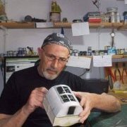
fozzy Posted June 3, 2010 Author Posted June 3, 2010 Hi guys sorry haven't posted for a week but family over from UK and everything has ground to a halt model-wise!! Looking forward to getting back to normality - that's me in my man-cave working on my Lysander! Cheers Fozzy
Erwin Posted June 3, 2010 Posted June 3, 2010 Very nice work so far. Reminds me of my balsa Guillows kits.
avro683 Posted June 4, 2010 Posted June 4, 2010 That's really nice work Martin, if you don't mind me asking why did you pick that scale?
fozzy Posted June 4, 2010 Author Posted June 4, 2010 That's really nice work Martin, if you don't mind me asking why did you pick that scale? Hi Tony Obviously I like large scale and I have always found the Lysander's cockpit glass and area interesting because you can see so much.So I thought that the bigger the better!!!(not being too big to fit in the display cabinet!!!)I scratch built a 1:30 Sopwith Camel once and loved the ease in replicating parts in that scale(on website)....thanks for your interest Fozzy(Martin)
fozzy Posted June 4, 2010 Author Posted June 4, 2010 Hi to all My family have now departed back to UK so its back to the work bench!!!.....and the dreaded cowl!!!!! So as you can see from the photo I started by laminating 6 pieces of 5mm balsa together with glue and left to dry overnight.With a compass I drew the front view shape of the cowl on what at the time was a block of Balsa wood.......does that make sense? Difficult to explain as I am new to this.....so apologies! Then the shape of the cowl was sanded with fine glass paper checking all the time with the plans for the shape of the cowl.....see below The next stage was to drill out the centre of the cowl to house the engine eventually.An appropriate drill bit was used and then sanded down so that the engine cylinder heads will just touch the inside of the cowl.The front of the cowl was then tapered to shape. Oil cooler intakes were replicated by 2 pieces of stripped electrical wire and super glued into position. The Carburettor intake was sanded to shape out of a piece block Balsa wood and the exhaust was made out of stripped electrical wire cut to shape.The cowl flaps are plastic card cut to shape and super glued into position. When the cowl was completed it was then given the treatment of pvc glue and Johnsons Klear and then undercoated with Humbrol grey. The next job to do is to construct the Mercury Engine......This is one of the parts of the project Im looking forward to!.I love the challenge.............when constructed will post again cheers Fozzy Uilleann 1
Spads57 Posted June 6, 2010 Posted June 6, 2010 Martin, Outstanding scratch building.I dying to see what you do with the engine. Regards, Gregory Jouette
fozzy Posted June 7, 2010 Author Posted June 7, 2010 Here's how I did it.............. 1.First I made an engine back plate out of plastic card(this was simply the diameter of the cowl cut out of the plastic card). 2.With the block of Balsa I made the engine block taken from a template of the plan.This was sanded to shape......see my crude templates! 3. Next the 9 cylinders were cut to size out of a childrens plastic hand held flag pole....no expense spared!! 4.Next I wrapped the green garden twine wire halfway up each cylinder. 5.Followed by the top half being wrapped with telephone single cable wire. 6.Each of the 9 cylinders were then super glued to the engine block 7.Another block of Balsa wood was then sanded to shape the Crankcase and then I attached strips of plastic card to the front and rear and carefully placed little blobs of PVC glue to replicate bolts! 8.I then super glued the engine block to the rear plate............Working out exactly where the centre of the crankcase was I carefully drilled a hole through the crankcase through to the back plate.This would later take the Prop shaft. 9.The 9 Push rods were made out of garden twine wire and super glued into position...........see photo I hope this is not boring for you!! 10.Using Milliput I made an exhaust ring which fits on the inside of the front end of the cowl....this was smoothed out with a wet finger! 11.Now comes the hard part.....I now glued the engine and backplate complete inside the cowl,making sure the engine seen from the front is lined up and squared away!!...I always find this difficult as its all line of sight....so no beers before hand!!...checking all the time the alignment as it's drying and placing a make shift prop shaft into the hole and looking at it from all angles...I think you get the picture!!!...Any way I hope I got it right else the prop will spin unevenly..........Leave it all to dry and go tell the wife all the problems you got with your Mercury Engine!!...see what response you get!! 12.The oil cooler intakes made from insulation cable were put into position on the front of the cowl previously so its on with the exhaust pipes. 13.I cut 18 exhaust pipes to size using once again my favourite modeling material.....electric cable!!...and carefully or should I say pains takingly glued one end onto the top of each cylinder and the other end onto the exhaust ring,fiddly job but will look good when all is finished....well maybe.... 14.The last job is to cut out of thicker garden twine wire the rods that support the exhaust ring in place. Obviously I painted parts after each section of the build. .......................................................and that my friends is that!!....here's some pics........................... ......and some more pics......... ......and some more.. ........a few more..... ...sorry but cant seem to put more than one pic per post and I have down sized!! ...last photo chaps....Next posting will be starting to construct the cockpit area!!!.... bye for now...Fozzy Hi once again chaps Here comes the good bit.....Replicating the 890hp Mercury xII 9 Cylinder air cooled radial engine. Reference material for this build was taken from a fantastic book from a series called ORANGE SERIES and its the WESTLAND LYSANDER by JAMES KIGHTLY. I find that as long as you have good reference pictures,a bit of imagination and patience then you can replicate anything!!! The 1st photo shows the entire materials I used to build the engine.To complete the build I think it took me about 3 days. Uilleann 1
Recommended Posts
Create an account or sign in to comment
You need to be a member in order to leave a comment
Create an account
Sign up for a new account in our community. It's easy!
Register a new accountSign in
Already have an account? Sign in here.
Sign In Now