
bdthoresen
-
Posts
1,818 -
Joined
-
Last visited
-
Days Won
1
Content Type
Profiles
Forums
Events
Everything posted by bdthoresen
-
Hasegawa 1/32 N1K2 Shiden Kai (George)
bdthoresen replied to bdthoresen's topic in Works in Progress
Yes, I was just flicking through that book myself, and it looks as if the Pima example which makes up the majority of the book, has had the majority of its engine resprayed silver. Those guys have been known to be pretty methodical about their restorations, particularly since that airframe was from the Smithsonian, and has since been returned to them after their 10 year display agreement was up. As far as wartime images, there seems to be few of the Homare, and the ones I did find have differences. Everything from cylinder barrels to ignition leads, oil return tubes to pushrod tubes can be different colors. I am realizing that I might have to just take an educated stab at it, and just go for a “general” representation. As long as it’s plausible, I am ok with it. So few wartime photos exist of the Shiden Kai, especially towards the end of the war, that it is always going to be an educated guess. Thanks for stopping by! THOR -
Hasegawa 1/32 N1K2 Shiden Kai (George)
bdthoresen replied to bdthoresen's topic in Works in Progress
You know Turbo, I am not sure. There seems to be no color photos of the Shiden or Homare from the war. The photos of the restorations out there are all different, and the black and white photos out there are not definitive. Still studying it, I may have to make an educated guess. The conduits were silver, but I am not sure of the wires themselves. There will be washes and filters, for sure, but I need to give the motor a couple of days to cure. Thanks for the reply! THOR -
Hasegawa 1/32 N1K2 Shiden Kai (George)
bdthoresen replied to bdthoresen's topic in Works in Progress
And we have a silver motor. I used the technique from our own Kevin Futter, to decant some Tamiya AS-12 into an airbrush jar. I let it degas for and hour or so, and cut it 2/1 with Mr. Color Leveling Thinner. I shot it at about 20 psi, and the finish I have is nothing short of great (for me, anyway, I hate metallic paints!) Well, that’s it for me this week. I need to let this cure for a few days while I figure out the next steps. Thanks so much for following along. Until next time. THOR -
Hasegawa 1/32 N1K2 Shiden Kai (George)
bdthoresen replied to bdthoresen's topic in Works in Progress
Thanks, Dennis. A lot of patience for sure, but I don’t have the steadiest of hands anymore. But I did apply a couple things I learned on this attempt. First, I used a sharp needle in a pin vise to punch a location to use my micro drill bits. Second, I drilled the sub assemblies before joining them together. The drill bit size was matched with the diameter of the wire with a set of digital calipers. Third, I used lead wire for the first time, and after learning its quirks, I am now a convert. It can be manipulated so easily, but also holds its shape well. Minor knicks in the wire can be burnished out with a smooth round toothpick by gentle rubbing. And fourth, I used two pairs of tweezers, with no real sharp edges, to manipulate the wire into their final locations. I had used Gorilla Gel Superglue to anchor the Ignition wires to the cylinders at the spark plug locations. Once dry I assembled the engine sections, and used some tape to stick the engine facing up on my workbench. This allowed me to have two hands free, which was huge. I then trimmed the leads to length, inserted them into the ignition ring behind the reduction gear housing, adjusted their shape, and then applied tiny drops of Thin CA into their locations allowing the capillary action to suck it in, locking them in place. Made the wire ties the same way. And......done. Tedious? Absolutely. Wicked cool? I think so! Give it a go, you might surprise yourself! Anyway, I have now primed the engine with black, Mr. Surfacer 1500 thinned 2/1 with Mr. Color Thinner. I have also decanted some Tamiya AS-12 into a clean jar to off-gas for an hour or so, which I will spray a little later. The black has tied in all of the different materials nicely, and it makes all the extra tedium seem worth it! More to follow later when I shoot the silver. That will probably be it for the weekend. THOR -
Hasegawa 1/32 N1K2 Shiden Kai (George)
bdthoresen replied to bdthoresen's topic in Works in Progress
Afternoon again, all. Stayed quite busy with the Homare engine last night, having completed the ignition wiring and wire ties. I used .015” lead wire applied into predrilled holes using gel CA, and then used the offcuts to make the wire ties. As I said, the wires are not accurate, being more “representative” of what actually should be there. There are a few defects that I still have to burnish out before primer, but it’s a 10-15 minute job.....I will then airbrush a coat of Mr. Surfacer Black 1500 over the entire engine. Once cured, a spray coat of Tamiya AS-12 silver will be applied, as the Homare was a fairly bright metallic engine......Anyway, here she is as she sits right now..... And a test fit of the engine, prop spinner and cowling. Not much to be seen normally. But since the spinner is removable, a bit more is visible in there..... Well, that’s it for now. Off to do burnishing, and priming. Thanks for stopping in! THOR -
Hasegawa 1/32 N1K2 Shiden Kai (George)
bdthoresen replied to bdthoresen's topic in Works in Progress
Troy, thank you. THOR -
Hasegawa 1/32 N1K2 Shiden Kai (George)
bdthoresen replied to bdthoresen's topic in Works in Progress
Thanks RJ.....wilco! THOR -
Hobby boss A26B “Intruder” —> Modeling News
bdthoresen replied to Rick Griewski's topic in LSP Discussion
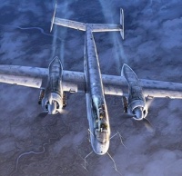
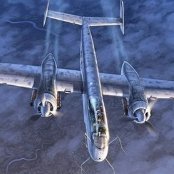
Yeah Karl, I noticed that to. Most of the shapes are close enough to be massaged into place, but the engines are going to have to be replaced. That is the biggest issue I see so far. The other problem I see is the engine nacelle shape is a bit bulbous, rather than tapered like the original. I will still build one, having spent a bit of time around A-26s throughout my career. Love those birds.... THOR -
Hasegawa 1/32 N1K2 Shiden Kai (George)
bdthoresen replied to bdthoresen's topic in Works in Progress
Engine update- Well, I decided to go ahead and add the remaining oil tubes to the front bank of cylinders using the same techniques as illustrated above. I also shaved off the “nubs” that Hasegawa molded to the front ignition ring, and applied some homemade styrene nuts in their place. Once cured, I will drill each one out, as well as the styrene nuts I added to the cylinders (to represent the lead connections on the spark plugs)- the lead locations will be a bit fictitious, as the Homare has double wire connections around the ignition ring, while the kit only has singles. So the wire routing will be more representative than actual, but it will be a damn slight better than nothing at all. I also added a few nuts to represent fittings on the propeller governor as well, just to add some interest......so far so good. That’s all for now. As I said, waiting for the glue to dry completely before drilling up the final wire locations. I realize that most of this will not be seen; But being that the prop is poly-capped, and therefore, easy to remove, helps in being able to see the details.....Thanks for stopping in! THOR- 39 replies
-
- 12
-

-
KH T-6/Harvard Kicked Up A Notch: Apr 14/20: Finished!
bdthoresen replied to chuck540z3's topic in Works in Progress
That’s the scheme I would love to do! What a machine!!!!!! THOR -
KH T-6/Harvard Kicked Up A Notch: Apr 14/20: Finished!
bdthoresen replied to chuck540z3's topic in Works in Progress
Looks great Chuck, nice work. Looking forward to the next installment. I would vote for the Tempest, next, in high-speed silver! THOR -
Hasegawa 1/32 N1K2 Shiden Kai (George)
bdthoresen replied to bdthoresen's topic in Works in Progress
Time for a small update. I started work by installing the shell ejector chute inserts to the wing undersides. Unfortunately, as in most Hasegawa builds, they don’t fit great, and usually end up having seams that don’t occur on actual panel lines of the original aircraft. Using the Aero Detail book on the George, I filled all of the seams that don’t exist on the real bird... I used GS Mr. Dissolved Putty, and it is currently curing as I type this. I also started working in the powerplant assembly, and had experimented with the fit inside the cowling with the spinner installed, just to see what is visible. Not much. So I had decided that I was going to stick OOB with it. And that lasted all of about 10 minutes. But I did decide to only add detail to the front bank of cylinders, as that is about all you can see. I decided that I was going to add the oil lines for the valve train at the cylinder heads, as well as an ignition harness. Hasegawa has two small bumps on each cylinder head that represent the connection points for the oil lines. I decided to try a proof of concept on one of them, to see if it is even worth the effort. I center punched each bump with a sewing needle, and drilled it with a .0205” microbit. I then used some .020” brass rod, and bent it into shape..... I then used the same drill bit to center drill a piece of .040” hexagonal rod, and then sliced it into about 1mm discs. I then added one to each end of the oil tube to represent the b-nut connections. I then installed the oil tube to the cylinder head using gel superglue, and then slid the b-nuts down to the cylinders, and applied Tamiya Extra Thin to weld them down. So, what say you folks? Worth it? Thanks for looking. THOR- 39 replies
-
- 11
-
-
Hasegawa 1/32 N1K2 Shiden Kai (George)
bdthoresen replied to bdthoresen's topic in Works in Progress
Thanks Mike! Appreciate you stopping by! Thanks Jeff. One of the better ones I have done in awhile. Also am loving being on this Japanese kick right now! Thanks, Thunnus. I tried to get them to look like they were a bit of a mess. This airplane was a brute, and sometimes I think the Raiden gets compared to the T-bolt because they have the same name. But the Shiden Kai was a monster, and a formidable adversary against the Hellcats and Corsairs they desperately tried to defend against. Anyway, back to the build. Thanks all! THOR -
Hasegawa 1/32 N1K2 Shiden Kai (George)
bdthoresen replied to bdthoresen's topic in Works in Progress
“Meanwhile, behind the facade of this innocent looking workbench”...... As I said, I practically blinked and had an assembled airframe. The bench..... I was surprised at the wing and horizontal stabilizer fit in some locations, some for good reasons, and some for not so good reasons. Allow me to explain...... The main wing root seams were extremely tight, which was a relief because Hasegawa has some lovely molded reinforcement strips along the fuselage wing root fairings. A slight polish of 0000 steel wool along the seams will clean them up nicely. The underside trailing edge seam was fairly tight as well, with just a pinhole showing up, probably from the liberal amount of Tamiya Extra Thin. I have to study my reference materials and figure out what parts, if any, of this seam existed in reality. Also notice the slight panel line misalignment at either side of the glue joint. Another interesting thing here is the the lower wing’s meeting of the trailing edge wing root fairings on the fuselage is not precise. The lower wing half is wider than the fuselage, creating an underside step, or “underbite”..... And lastly, the horizontal stabilizers. They feature an interlocking tab system that ensures they stay perpendicular to the vertical stabilizer. However, I found that the tabs were an extremely tight fit to each other, which in turn caused them to slightly push away at the tail glue joints. You can see the slight mismatch at the “kink” in the tail fairing. Overall, I am impressed by Hasegawa’s overall fit, with just some minor annoyances to attend to. I also am fully prepared to accept that some of these minor annoyances were self-induced. I hope to get all of these scrubbed up quickly, so I can move on to the engine and gear build-up. But my plan is to tend to all these defects and rescribing now, so I can call this sub-assembly done. Comments and critiques always welcome. Thanks for looking- THOR- 39 replies
-
- 14
-
-
Hasegawa 1/32 N1K2 Shiden Kai (George)
bdthoresen replied to bdthoresen's topic in Works in Progress
Thanks Dennis. Shortly after that pic was taken, I sneezed, and an aircraft was sitting on the bench! I was pleased at how good the fit was overall, but there were a couple of small problems I did not foresee. I will shoot some photos a bit later and explain. Thanks for stopping in! THOR -
Hasegawa 1/32 N1K2 Shiden Kai (George)
bdthoresen replied to bdthoresen's topic in Works in Progress
Weathering of the cockpit now complete, I figured I would lay out all of the components for one last photo before final assembly and insertion into the fuselage. THOR- 39 replies
-
- 14
-
-
Actually, that is not a bad idea, Ray. Peter, I know you said that you were exploring options on how to help bring down your build costs, (and for those of us who do not subscribe to Patreon or similar services), this might be a viable option to help. If you are developing parts for this kit, you might, as Ray suggested, make copies of things you develop like photoetch, placards or instrument related stuff and offer them for sale for those of us who are also wanting to build 1/18 Wurgers. I for one would be happy to purchase some things like that to help by large scale Dora along. Just some food for thought! Looking forward to the next update, regardless! THOR
-
Alan, the cowling in the middle appears to be from the Trumpeter kit because of its odd shape. The two outside ones are the Hasegawa kit cowls by the looks. Quite a difference. Love the work so far, Bill. THOR
-
Brad- looks great, man. A tough kit to be sure. Looking forward to seeing what’s next..... THOR
-
German F-86K, Neuburg AB.... FINISHED..Part 2
bdthoresen replied to Daniel Leduc's topic in Cold War Jets
Looking good, Dan. The cockpit looks great. Looking forward to the paint job! THOR -
Wow, not a fan of World War 1 builds, generally, but I am enjoying this immensely. Please keep the updates coming! THOR
-
Nice problem solving, Breaker. I have a single seat en route as we speak, I have always loved the C ever since my little brother gave me his old Monogram kit when we were children. Looking forward to more updates! THOR
-
Actually, I remember an article on this bird, and Inseem to recall they had found another photo of it on the ground, and it was in the factory scheme of 70/71 over 65, with the squiggles done in white for winter. Tough scheme, would be awesome if you pull it off! THOR
-
Just, wow.
-
Ah, using the Jv44 version of this same kit as the basis for my big build. Looking forward to what you do with this, as not being computer literate enough to design and print my own decals, design my own photo etch, etc. stopped me dead in my tracks.....so she sits waiting for my return as a pile of parts. Good Luck my friend- THOR