

KevinCG
-
Posts
36 -
Joined
-
Last visited
-
Days Won
1
1 Follower

Recent Profile Visitors


-
 daHeld reacted to a post in a topic:
Skinning 1/32 models in metal... a tutorial
daHeld reacted to a post in a topic:
Skinning 1/32 models in metal... a tutorial
-
 daHeld reacted to a post in a topic:
1/18 P51C Mustang "Lopes Hope the 3rd"
daHeld reacted to a post in a topic:
1/18 P51C Mustang "Lopes Hope the 3rd"
-
TAG reacted to a post in a topic:
1/24 Scratchbuilt P-38L A retrospective to the present
-
Starfighter reacted to a post in a topic:
1/24 Scratchbuilt P-38L A retrospective to the present
-
Greg W reacted to a post in a topic:
1/24 Scratchbuilt P-38L A retrospective to the present
-
Greg W reacted to a post in a topic:
1/24 Scratchbuilt P-38L A retrospective to the present
-
Troy Molitor reacted to a post in a topic:
1/24 Scratchbuilt P-38L A retrospective to the present
-
Marcin_Matejko reacted to a post in a topic:
1/24 Scratchbuilt P-38L A retrospective to the present
-
rafju reacted to a post in a topic:
1/24 Scratchbuilt P-38L A retrospective to the present
-
BiggTim reacted to a post in a topic:
1/24 Scratchbuilt P-38L A retrospective to the present
-
 KevinCG changed their profile photo
 -
1/24 Scratchbuilt P-38L A retrospective to the present
KevinCG replied to KevinCG's topic in Works in Progress
Many Thanks for your kind words Captain, Kevin, Out2gtcha, Braham, Mike, and I apologize for not replying sooner to everyone but events other then modelling have somewhat overtaken me the past twelve months. As you can guess I do not know hoe to multi-quote in the one post so have compressed my replies into a single post. Please forgive. Cheers Kevin -
1/24 Scratchbuilt P-38L A retrospective to the present
KevinCG replied to KevinCG's topic in Works in Progress
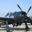
G'day Everyone, First of all many thanks for the kind comments guys. Craig to answer your question I use ordinary contact adhesive - the sort one would use for gluing linoleum etc. In Australia it goes under the name of KwikFix and is marketed by Selleys. It can be removed with lacquer thinners or toluene and you can also by a specialist solvent. However they all attack plastic so caution is required. Finishing the model Since my last post the model has now been finished and this involved attaching numerous pre-assembled parts and also painting etc. The biggest job and one which I had been dreading was the u/c doors. On the P-38 they are attached by Studebaker hinges see below and I had dreaded this part of the build. To re-create these I had several sheets of photo-etch made up in the belief that i could then make the individual hinges and they would work. Unfortunately dealing with the small brass pieces proved almost impossible and in the end they were glued in place. I had to make a small jig to hold the doors in place whilst I affixed them to the actuating cylinders and then methodically set about gluing up the hinges on each door. A fiddly time consuming job that took the best part of two weeks. Once this was done the wheels could be attached. I had these 3D printed by my nephew who runs an engineering shop and they came up beautifully. Next was the canopy and although I had built a hinge I decided to glue the top piece in place but not locked down. I figured this was a safer option than having the top section sticking up in the breeze waiting to be knocked off! Final details for the superchargers, lights radio aerials etc were attached, once painting was completed. The aircraft was painted prior to all these biyts and to facilitate painting a rough jig was constructed. This made spraying markings etc considerably easier than manhandling a very heavy model with which the slightest slip could result in ruin! Colour scheme. This was a vexed question. I had from the beginning decided to finish it in the markings of Jack Purdy from the 433rd FS of the 475th FG in the Pacific. There are a number of schemes floating about in various publications, however nothing is simple. I managed to track down his family and they were very helpful but unfortunately many details had been lost over the years. Purdy flew several P-38s marked with the name Lizzie and toward the end of 1944/45 he had two; Lizzie IV and Lizzie V both of which crashed within a short space of time. In tracking down the serial numbers of these a L1 and L5 respectively it would appear that serial numbers have been mixed up when it comes to applying markings. The markings of the restored example in the Museum of flight would appear to be a combination of both the IV and V Lizzies. The serial number on the nose does not fit for an L-5. After much searching and exchange of information the final scheme was based on that shown in the Osprey book on the 475th FG which I think on balance is probably the most accurate depiction. The blue colour was also a subject of much debate and and I must acknowledge the help of a number of LSP members in earlier correspondence on this. Markings were sprayed using stencils cut from Frisket and in the case of the flags and No-step, photo etched stencils from Custom photo-etch in Melbourne. The airframe stencils are dry transfers made by Allout graphics in West Vancouver and they worked a treat. Anyway to cut a long story short here's the beast in its glory and so after 8+ years of toil the story is concluded. I concede the photos could be better - apologies. In conclusion this build was a challenge and were I ever stupid enough to do another I would do things differently and follow more closely the original design by building and attaching the outer main planes separately to make handling easier. To permit the model to sit on its u/c there is a large amount of lead in the nacelles and I estimate the completed model weighs well over 5kg. Its now safely stuck in its cabinet. Apologies for not providing more details of the build - I guess I'm just not that good at this sort of thing. Many thanks for viewing Cheers Kevin- 112 replies
-
- 25
-
-
-
1/24 Scratchbuilt P-38L A retrospective to the present
KevinCG replied to KevinCG's topic in Works in Progress
G'day Folks, First of all many thanks Peter, Shawn and Mark for your kind comments and others who posted messages - they're much appreciated. Well so much for good intentions! I note it's nearly 4 mths since I last posted and to make it worse I've taken B***er all pics of what I've done since , no excuses I just get engrossed and by the time I remember it's too late. The model is now on the last legs of an 8.5 yr journey and being readied for painting so its probably a good time to post what has happened since March. After tidying up the canopy it was time to go to the next challenge - the large wing root fairings. Fortunately these were in upper and lower halves which made the job somewhat easier. To avoid damaging the model I used some of the spare vacformed fuselage to make a pattern onto which the litho plate could be formed The same fairing was built up on the model as below together with a cleaned up fairing final fitting and trimming was done on the model after marking and masking out. A job guaranteed to test anyone's patience. The final result came up ok once both pieces were mated and glued in place Having got through this experience it was onto the undercarriage doors which were fabricated out of litho. The hinge fittings were fixed in place so that the Studebaker hinges can be fitted when the model is painted and ready for final attachment of all the pieces waiting to go on. A job I'm not looking forward to as it promises to try my patience to the limit. Th e cartwheel resembling objects are the covers for the main wheels which were fashioned by hand from thin sheet At this point it was time to attach the upper parts of undercarriage and cover the pivot points with Litho plate. The various elements had been built several years ago. It took me a while to figure out what all the various bits were that I had made and how it went together The good news - the model sat level, the consequent of numerous mockups and measurements at various stages. The bad news was that it was still tail heavy despite all the lead weight in the nacelles. A hole was drilled in the front of the nacelles large enough to 'post' through round number 1 fishing weights coated in epoxy. A further half kilo of lead was added in this manner. The model is now very heavy (several kgs) and then the next mishap. Then the really bad news! Despite the stout u/c mount as per the prototype) I managed to twist the model whilst it was balanced on one leg, which with the weight of the model caused the leg to rotate in the mounting tube. This had all the appearance of a catastrophe so I went for ride on my bike to work off some anger and work out what to do!!! I have learnt through bitter experience that after serious mishaps it is better to walk away and calm down before attempting any rectification. The fix was to carefully drill two 0.8mm holes diagonally through the entire assembly into the nacelle on each side nd pin with steel rods. The contour of the nacelle worked in my favour as it sweeps up into mating with the wing. This worked much to my relief but I am a bit more circumspect about how it is handled now. I did the other leg the same way figuring it was bound to happen there as well at some stage if I didn't. Litho plate was then affixed in place to complete the plating of the beast. Next was making the airbrakes that sit underneath the wing The underwing pylons which were shaped out of plastic card and then skinned with lithoplate Finally propellers were cast in resin after making port and stbd patterns - yes they were different as they rotated in different directions At this stage the model could be painted prior to final assembly with u/c etc etc and light is appearing at the end of the tunnel. I had hoped to have this model ready for the Melbourne expo, which clearly it wouldn't have been however with Covid that was rendered irrelevant but it will be good to have it finished Many thanks for looking Cheers Kevin- 112 replies
-
- 20
-
-
Peter there was an article published in Flugzeug Classic (4/2018) on this aircraft may be helpful. It is in German however. Whilst a number of the photos in this article have already been put up here, there are some others and of course several pages of text describing it in more detail. Email if you're interested and I will send you a PDF. Cheers Kevin
-
1/24 Scratchbuilt P-38L A retrospective to the present
KevinCG replied to KevinCG's topic in Works in Progress
G'day Everyone, Apologies for the rather intermittent nature of my posts but modelling time is so precious I find myself immersed in it once started and then forgetting 1 - to take pictures and then getting so engrossed I forget I should post. I thus apologise for the rather poor collection of WIP shots. I must express my gratitude or the kind comments from my last post. After 9 years the end is in sight I hope. The seat required finishing. A yellow life prserver was made from 2mm card and bent with the aid of steam to conform to the seat contour. texture was carved into plastic and the pins from small pin heads. The bead was from this stretched sprue. once painted yellow the stencilling of US ARMY AIR CORP was sprayed using a photo etched mask. Seat belts and buckles were from masking paper treated with acryllic paint and photo etch buckles and a hand made clasp/release lever. Seat is shown leaning against a ball point pen Once finished the seat could be mounted in the cockpit. Fitting the supporting brackets behind the seat was a bit tricky, like everything on this aircraft. However once it was all in place it sort of looked the ticket. Having moulded a canopy in plexiglass and constructed a brass frame for windscreen and reay portion it was necessary to do the radio tray and radio fitment. This proved a little problematic in that this was varied however i decide that as this is a L version and will have 1945 markings the SCR 522A would be the most appropriate fit based on everything I could find from various references. A metal radio tray was constructed as per the part's manual and the appropriate radio boxes were constructed from plastic card painted and mounted on the tray. The armour plate behind the pilot seat was also fitted and mounted. Wiring and sockets were from thin gauge copper wire and turned from Aluminium tube respectively. The following pic shows the result before rear canopy was added. Once this was completed the rear canopy could be attached. This was polished inside with Novus polish and then the outside masked off first of all to indicate the areas to be litho-plated and then reversed to prevent damage. Unfortunately i forgot to take pictures of the upper internal bracing which was quite distinctive but it will be seen once masking is removed. Masking the outline of the framing took considerable time on the multiple compound surface as it had to be absolutely correct otherwise it will show up like the proverbial. the next two photos show this and the start of the litho-plate framing. The rear was also riveted using 0.5mm aluminium rivets as per the original. I have removed some of the masking so this can be seen. These last two pics hopefully illustrate the rechnique. Detailing of the front frames is yet to be added as is the rear skinning of the canopy That's all for now but hopefully the canopy can be finished over the next week or two. I think the worst of that is over. The next phase is then the wing fillets. Cheers Kevin- 112 replies
-
- 20
-
-
1/24 Scratchbuilt P-38L A retrospective to the present
KevinCG replied to KevinCG's topic in Works in Progress
Thanks Mark Many thanks Mike I used cooking oil the cheapest I could get and heated in a small Alfoil roasting tray to about 150 C (using a cooking thermometer). If you get too much higher then the acrylic starts to bubble. Heating in an oven also works but i find the oil method reduces the probability of stretch marks on the canopy from being pushed through the mould. Cheers Kevin -
1/24 Scratchbuilt P-38L A retrospective to the present
KevinCG replied to KevinCG's topic in Works in Progress
G'day folks, First of all many thanks for the comments and kind words and messages they're much appreciated. In looking at this thread it is almost six months since i last posted my apologies. One has so little time for modelling and gets so involved in the process that I forget to take pictures and post updates thinking I'll do that tomorrow. There's been a lot of tomorrows and also explains some of the hit an d miss photographic efforts! Since that last update work has continued on the cockpit and canopy. Detailing the cockpit was somewhat tedious and took many hours. Despite the many references it was surprisingly difficult to get the exact layout and content right due to the many changes which occurred in the P-38 construction program. This is as good as I could get but I'm prepared to admit that there maybe some errors or omissions. The scale instrument panel was constructed from Al sheet after being traced directly from Leroy Weber's drawing and copied onto a piece of paper to create a PDF which was then enlarged 12 fold to make a base over which the instruments could be drafted. Hopefully this pic conveys what I mean. This 'stencil' was placed underneath drafting paper onto which the instruments were drawn. Some detail was omitted in order to get a better scale effect. I have found that reducing instruments down to 1/24scale using real life dimensions renders the final effect a little disappointing. Others may disagree. The resulting diagram was then made into a PDF and colours reversed using Microsoft Paint. The panel was then assembled as a three layer sandwich of the Aluminium panel, clear transparency and Instruments was created The following is the result which due to the poor photograph probably does not do it justice. Control boxes were constructed from plasticard or metal whilst the toggle switches were individually turned on a lathe from thin Al rod. The following three views show the left, front and right hand sides of the cockpit. Note the seat is not fitted yet as this will go in after the rear canopy is installed. Nor are the actual throttle controls as they would likely be damaged during subsequent work on the canopy. Cockpit placards were from Airscale. Fortunately due to the construction of the P-38 this work could be done on the cockpit tub ex the actual aircraft. Apologies for poor i-phone images but its the best I've got. Once the cockpit tub was more or less completed it was glued into the fuselage and work commenced on the seat This was constructed from brass sheet folded with a base inserted as per the following two pics. In the first pic shows the main seat component without the brass base which was soldered into place. The white plastic piece is the armour for the seat pan there is a base and back armour plate. Once this was assembled a thin piece of stretched sprue was attached to the edge of the seat to simulate the knurled edge of the original which you can hopefully see in the next pic. The seat was then painted and set aside for completion later with seat belts and buckles etc. Still undecided about material for belts. The next and most demanding task was the canopy. Using the polished master two types of material were used, thin 1mm acrylic sheet and 1mm PETG. The former was heated in an oil bath and then press formed with the male mould and produced the following. This is a messy process and was done outside on the BBQ. I also might add that it took a number of pressings to get exactly what I wanted. The picture below shows the original pattern polished master and resultant clear piece. Different size is due to distance from camera lens. A rotary razor saw was used to separate the pieces taking extreme care due to the rather brittle nature of the material. Only the rear section will be used on the model as i need this to be reasonably strong in order to form the lithoplate over the rear fuselage structure. Canopy frames were constructed from brass channel and then glued into place for the windscreen onto which will be attached the individual panes from PETG sheet. The rear section is somewhat more complex and I milled a 1mm wide x 0.5mm strip off the the front edge of the acrylic section into which the brass frame was pinned using pins cut from 0.4mm brass rod. The next phase is detailing the radio compartment and then the rear canopy can be attached. If you have got this far many thanks for looking and I'll endeavour to be a bit more regular in postings. Cheers Kevin -
G'day Peter, Your work is superb. Congratulations With respect to your your seat belts I feel a word of caution maybe required as I have noted that there can be problems over the longer term using lead where it comes into contact with some other metals due to presumably differences in galavanic index. The lead or other metal simply disintegrates over time, the metal with the lower index (ie more -ve) dissolves or goes to powder. This happened to me many years ago on a 1/24 scale Me 109, where the belts just disintegrated after 10 or so years. I have subsequently eschewed lead. I have seen similar issues with white metal on older models in museums etc. This may not be an issue in your case as I do not know what from what metal you have etched your buckles and clasps but it maybe worth checking. Any difference greater than 0.25mV is likely to cause an issue. According to Wikepedia Lead has an index of -0.70, brass -0.4, Copper 0.35 and nickel -0.3. It gets a bit more complicated when alloys are involved. I hope this doesn't apply but it's worth knowing for the future. Cheers Kevin
-
1/24 Scratchbuilt P-38L A retrospective to the present
KevinCG replied to KevinCG's topic in Works in Progress
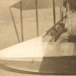
G'Day folks, First of all many thanks for the kind comments, they're very much appreciated. Its been a long while since the last posting (a lot of work with travel commitments) but some more progress, albeit rather glacial. This time attaching the fuselage to the wing assembly and finishing the plating on the lower fuselage. Due to the way the fuselage is split by the wings I decided to do the entire canopy as a separate section and attach at a later date - next post hopefully. The fuselage was glued and pinned to the wing cutout as shown in the pic. The dark coloured dots are where pins were inserted and glued into the wing rib for added support. The fuselage is quite heavy and if picked up or held toward the nose there is considerable leverage on any joint with the wing. Once set the model could be inverted and the underside covered with lithoplate. This again took some time due to several discards and also corroborating with photos the correct disposition of skin panels. The next image shows the final result as well as the holes for the identification lights which will be glazed at a later date. At this stage a master pattern and subsequent mould was built for the canopy structure and then a resin copy cast from epoxy polished and used to form the final canopy from clear sheet. A pattern was also made for the cockpit area so that the fuselage and canopy would form a snug fit. These two stages are illustrated in the next two photos. This pic shows the polished resin canopy in the foreground and a second pattern placed on the fuselage to obtain correct fuselage canopy profile and plan view. Why was this not incorporated in the first pattern i hear people ask? Good question and the only answer is that it was not thought through properly - i.e. stupidity. The next photo is of a plan view of the same area. Once the area has been fared into the fuselage the canopy will be able to be cut out and in to sections so that the area aft of the mainspar can be affixed to the wing uppersurface after the radio boxes etc have been built and placed on their racks. Hopefully it will be not so long until the next post when some more fuselage progress including canopy can be shown..- 112 replies
-
- 13
-
-
1/24 Scratchbuilt P-38L A retrospective to the present
KevinCG replied to KevinCG's topic in Works in Progress
G'day Everyone, I thought it had been awhile since an update but was somewhat surprised to see how long ago. As one can gather it is a slow process, work, looking after the property,the garden and of course its summer with heaps of produce to harvest etc. First of all many thanks for the kind comments it is much appreciated. If I recall correctly I had attached the rear empennage and drilled out the holes for the zillions of tiny rivets. It took a while to get back to that for a whole heap of reasons mostly indecision. With such a complex model it has taken a lot of thought as to when to attach the various elements to the model in order that they do not get damaged with subsequent work or alternatively have been left too late and thus are a pain in A*** to attach. In the meantime I tackled the exterior of the fuselage and covered the areas, that can be plated before it is attached the wings. As with the rest of the panelling on this model a great deal of time was spent researching the actual panel placement and shape. I started at the nose and fairings for the armament a painful and very slow process requiring multiple annealing and also destroying several pieces in the process. The pic below shows the first part of the the process At this stage the nose undercarriage was affixed at this stage and tucked into the well, so that I could plate over the access and location holes. I had left this area unfinished until now as there were two pieces of rod that needed to be threaded across the fuselage as on the original The next pic shows the area in question before sealing off. After the area was sealed and smoothed to the fuselage contour the rest of the fuselage could be plated and detailed At this point there was no delaying the simulated screws on the nacelles any longer. Actually it was not as bad as thought and only took about eight hours. Drilling the holes was the worst and I managed to go through a number of 0.45 mm bits. The heads of the rivets were 0.6mm which in 1/24 scale equates to a full size bolt of slightly larger than 14mm which was very close to what I had measured on the actual aircraft. The next pic is of half way through the process. Lastly I made the wing landing light lens, cover plate and transparency so i could prime the leading edge as per the original. The lamp reflector is bit of highly polished litho, with a bulb of turned perspex and the glass from vacformed PEG. Sorry about Cr***y pic but I do not have a macro. After the leading edges are primed I can attach the fuselage to the wing section. Thankyou again to those who commented and hopefully it will not be so long before next post.- 112 replies
-
- 13
-
-
1/24 Scratchbuilt P-38L A retrospective to the present
KevinCG replied to KevinCG's topic in Works in Progress
Thanks very much Peter, your efforts aren't too shabby either Time for another update. The previous post showed the plan behind re-attaching the fins and tailplane in order to obtain a strong joint. I am happy to report it worked. One of the advantages of using metal is that it is possible to get good fits and handling does not erode initial slots and gaps as can happen with plastic. The tailplane was first attached as per the post above and then after many checks that they were vertical the fins were permanently fixed in place the slots filled in with epoxy putty and the last panel which had been pre-cut affixed into place. The next task was to fit the fairings around the fins. This was another task to which I was not particularly enthused. I had made spare vacformed fuselages so cut pieces off the end and used these to fit around the fin and tailplane as per white inserts in the picture below. These were done in two parts, upper and lower. Once glued in place they were faired in with epoxy putty and primer taking care to mask off the previously applied lithoplate. For this task i got out my trusty lazy susan. This was a product I bought from an Aldi special buy some years ago. I think it cost about $12. it is glass so I then made a silicon rubber 'plate' that sits on top which stops models from sliding about and also protects their finish. It greatly aids modelling when painting and also where one has to continually move the model about to obtain different orientations in order to get the best access. The next step was to make the lithoplate fairing that covers these. Fortunately on the real aircraft they are in four pieces. these were shaped over the plastic using annealed lithoplate. The initial shape was derived from sticking masking tape onto the model and then drawing on masking tape around the existing outline of the lithoplate already attached to the model. Although a complex shape the method of using tape to provide the initial two dimensional cut on lithoplate worked well. Nonetheless each piece took about 1hr on average to fit accurately. The beauty of it was that as the piece fitted snugly it was relatively easy to ensure it fitted correctly in place when it came to gluing. lucky as one mistake meant starting all over again. I only had to do this once fortunately. Once in place they looked like rather smart if I may so myself. The slightly larger gap between this fairing element and the other one on the boom is intentional as this was also the case on the original due to changes made to empennage incidence after the first set of jigs were made. This was to help avoid issues relating to compressibility and pulling out of high speed dives. On the same note the mass balances were also made using Aluminium rod. The mass weights were turned up on a lathe The support strut was also filed out of rod and the pieces assembled as per below. For strength a 0.7mm hole was drilled into both the mass weight and end of the strut into which brass rod was inserted ensuring that the weight and strut remain united. These will be attached once the model is almost finished. I don't want to push my luck too much with the attachment rods! The next step will be inserting approximately 2-300 rivets around the empennage/boom join as per the actual aircraft and then joy oh joy I can move onto the fuselage pod. Thank you for looking. Cheers kevin -
1/24 Scratchbuilt P-38L A retrospective to the present
KevinCG replied to KevinCG's topic in Works in Progress
Thanks very much to all those who posted it is much appreciated. This post as promised will cover the rear empennage. As those who have followed this post will know both fins broke off the model due to my clumsiness and the fact that they have a thin and hence frail attachment to the booms. The boom at attachment is less than 10mm deep and the fins and tailplane are both only 4mm thick at their thickest point. Consequently when I dropped the model at one stage they both broke off. The result being inevitable especially considering the weight of lead inside the nacelles to prevent it being a tail sitter. This necessitated constructing new fins and tailplane that would withstand my hamfistedness when at the desk ie accidental knocks etc. To do this I constructed the tailplane in two halves split horizontally and with brass tube inserted to provide horizontal strength but also into which a vertical piece could be inserted so that the fins would be both vertical and also rigid enough to with stand the odd knock. The top and bottom halves of the tailplane were affixed together using double sided sellotape and sanded to the correct aerofoil shape. A span wise channel was cut into which the brass tube was inserted to provide rigidity and also an attachment for the square tube shown in the following pic. This tube will act as the key attachment point for both the booms and also the fins Hopefully the pic that shows the tailplane and the brass square tube into which the vertical piece will be inserted and also how this same tube serves as the attachment into the booms. The next pic hopefully conveys what I mean. It shows a similar slot for a vertical tube in the fins. The tricky bit is that all this has to be built so that it can be attached to the model after I have plated the fins and tailplane and added rivet fastener detail etc. It being very difficult to do this on the aircraft once assembled. I also have to leave the space for the fairings around the fins once it is fixed in place. Further more it also has to fit prefectly so that the empennage is both correct in the horizontal and vertical plane. Note also the annoying lockheed trailing edge which requires a thin piece of metal sheet onto which the skins are attached. On the real aircraft the skins were riveted onto this peice. The fins were made in the same manner as the tailplane being composites of layered styrene shaped to the correct aerofoil. Both the fins and tailplane were covered in lithoplate and to shape the leading edge piece for the fins a blank was made that would be able to withstand some strenuous pressure as it has quite a difficult compound curve. Several 'annealings' were required to get the piece correct. The next pic shows the blank and the fin element. The slot for the fin to fit over the leading part of the tailplane can also be seen. The entire tailplane and fin were plated except the area with the arrow on it which will be attached once the fin and tailplane are in place on the model. This was a somewhat tedious task as each fin has 25 individual panels and took approximately 6 hours to skin. I'm not sorry its finished especially as I had already done this once before!! It is unfortunately true that for scratchbuilders such as myself we only have one completed model to show for our efforts as generally speaking with the number of parts constructed that don't quite live up to expectations we have probably constructed the equivalent of 2-3 models by the time we are finished. The next picture shows the pieces skinned and polished ready for detailing. The pre-cut panels for attaching after assembly to the booms are also illustrated. -
1/24 Scratchbuilt P-38L A retrospective to the present
KevinCG replied to KevinCG's topic in Works in Progress
Thanks for the positive comments and likes guys. Much appreciated. -
1/24 Scratchbuilt P-38L A retrospective to the present
KevinCG replied to KevinCG's topic in Works in Progress
G'day again Large scalers, Its been a reasonable interval since my last post. This does not reflect a lack of time at the bench but rather the complex bast that is scratchbuilding. If you ever hear anyone suggest that they should build a large scale P-38 and then skin in it in Al sheet, suggest that they should perhaps have a clinical test for madness! Not only is it complex but 2x so because of the twin booms. Anyway on with the build. This post covers the fairings between the wings and booms and the supercharger intakes. This took many hours to do not only because of the complex shapes but also in scouring hundreds of photos and drawings in order to ascertain the correct layout of the skins.This was particularly difficult for the inner fairings as there were very few pics available and certainly nothing of any accuracy from drawings. As it transpired they were comprised of many pieces of which the tiny trailing edge fairing at the boom/wing joint was th emost difficult. For each of these 4 pieces I probably made 5-6 to get the correct one, and this despite multiple annealing to shape the piece. The following pic shows this The gap that is not skinned will be completed once the u/c is fitted. This has been omitted at this stage for ease of handling. There is still the panel beneath the engine to add- the area under the green padded tape. Again this has been omitted until after the u/c has been added, to prevent damage. Once these fairings were completed it was on to the supercharger intakes. To make these a plastic pattern was made from formers and epoxy putty. Once shaped this pattern was used to cast a mould. Th efinal pieces were then vast in epoxy resin. The rationale here was that an epoxy component would be stronger than plastic when it came to forming the metal skin. The picture shows the component and the skin shell that was shaped over the epoxy piece. Th epic below shows the reverse side. The dark colour of the al is from the annealing process The actual intakes were comprised of 4 skin elements; upper, lower, front rim and inside fairing. The rim was turned from Al tube. To make the elliptical fairings that sit between the intake and booms another pattern had to be made. This was then glued to the original fuselage master and Al sheet shaped accordingly. The next pic should illustrate what I am trying to convey. Th efinal result for the two intakes is shown next. I must apologise for the camera work. I only have an iphone so the depth of field etc is not the best. I hope however that the gist of what I'm trying to convey is reasonably clear. If not please ask. My next post will cover the top of the booms and the fitting of suprechargers and the various vents inlets etc. Until then all the best Kevin- 112 replies
-
- 14
-
-
1/24 Scratchbuilt P-38L A retrospective to the present
KevinCG replied to KevinCG's topic in Works in Progress
G'day Again - Its been awhile and I haven't died just had a lot on, harvest, preserving, firewood collecting and splitting, painting, some consulting work and of course some modelling. The last post back in January saw the booms and wings joined and the skinning covered with protective paper. The next task involved recreating the area on top of the booms and the one area that I had been mulling over for a long time - the superchargers. This area needed to be completed so that the aluminium and stainless steel skin could be finished around the wing boom area. To make the top of the nacelles around the supercharger area a channel was first constructed into which the supercharger and its ducting could be installed. This was constructed from 1mm plastic card and affixed to the upper wing surface The picture also shows the area for the actual supercharger marked out for removal. Once this channel was in place was in place on both booms the external skin could be added. This was cut from the piece that was removed from the original vacform of the booms and shaped to fit. It was trhen glued into place and fared into the upper boom contour using epoxy putty. The forward end of the channel for the exhaust duct and heater is flared so a pattern was created out of 2mm card wrapped in cling wrap and then pushed into some epoxy putty to create the correct shape in plan view. Once set the cling wrap peels easily away from the epoxy putty. (I find this a very useful to create male/female patterns that need to be mated together to form a snug fit.) The next step was to create the supercharger itself. A couple of spare wheels from the spare box served as the basis for the turbine area, however the duct surrounding the blades is helical and not of constant cross-section. This required a bit of filler and offsetting the centre of the turbine using the lathe to create to the space into which the blade structure would be fitted. The blades for the bucket wheel are very fine and for this purpose a number of identical photo-etched pieces were produced for me by Adrian Prassler from Custom Photo Etch in Melbourne. These pieces are shown below together with the cooling cap which sits on top of the bucket wheel. To make the bucket wheel and give it some depth three individual pieces were laminated together taking care to ensure they were completely aligned. These were then inserted into brass rings cut from brass tube, which were inserted into a second close fitting brass ring that sits on top of the actual supercharger. The cooling cap was also a test of patience and was made in two halves from fine brass tube filed in half lengthwise and plastic that were joined together onto a slightly oversize silhouette cut from Lithoplate. This mimicked the actual structure on the real thing. The two halves were then cemented together to produce the piece shown in the picture above. To produce the second piece which is on a horizontal plane and disappears into the side of the channel 2 pieces of lithoplate was formed around wire to make both sides. They were then cut out and joined together. To make the slightly domed cap on top of the bucket wheel on which the cooling cap sits. To make the exhaust duct thick aluminium tube was annealed and then placed between a vice to create an oval cross-section. The tube was then bent to the correct shape and the three steps filed into it to create the impression of a sleeved joint. The forward end was bifurcated to recreate the two exhaust inlets and a slot cut for the intake for the heater intake at the very front. The waste gate was made from aluminium tube and connected to the supercharger after a hole was drilled to fit the valve. The almost finished piece is shown located in-situ below. it only remains to fit the various clamps around the exhaust and waste gate and the valve. The former have been turned from Aluminium tube and again flattened to the sale cross section as the duct itself. I am reasonably pleased with result which is good because it hits you right in the eye when you look at a P-38. Once the skin is applied it should look reasonably smink.- 112 replies
-
- 10
-