

allthumbs
-
Posts
906 -
Joined
-
Last visited
-
Days Won
4
Content Type
Profiles
Forums
Events
Everything posted by allthumbs
-
Tamiya F-16CJ:UPDATE:8/29/15: DONE AND IN THE BOOKS
allthumbs replied to a topic in Works in Progress
Way to stick with it Peter! Your Vipor looks terrific. Rich -
Top notch work Peter...following every update. Rich
-
Danny, Interesting project - very well researched and executed. Eager to watch it take form. Cheers, Rich
-
The new cross section looks great...I think you nailed it! Cheers, Rich
-
You're off to a great start Danny. That landing gear leg polished up nicely. Can you describe your technique for achieving that shine? Rich
-
1/32 Electric Intruder - Grumman EA-6A Conversion
allthumbs replied to allthumbs's topic in Works in Progress
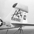
Thanks Ben! I appreciate your kind words. Here are the tools used to create the rivet/fastener detail on the tail... To help ensure straight rows and even spacing, I like to use a Hasegawa Rivet Guide (two are pictured here - those flat stainless steel strips that look like measuring rules). Four guides, all with different pitches, are provided in the set. Once positioned on the model, the guide is taped securely in place to prevent slippage. Then I take my scribe (sewing needle chucked into a hobby knife handle) and start poking holes, using light to medium pressure. As we quickly discover, this technique does not remove any material from the model. Plastic is simply displaced, creating a tiny raised collar around each hole. Instead of using sandpaper to knock down these rings, I prefer to shave them off using a sharp double edged razor blade. This method is cleaner and prevents material from being pushed back into the cavity. Next, I take a small twist drill - I used a #83 on the tail parts (.30mm) - and give each hole a couple of light turns by hand. This last step is tedious and time consuming, but I like the effect it yields. The holes become more uniform and cylindrical. Final clean up involves light sanding followed by a scrub with an old toothbrush. Thanks Tomcat. I've agreed to let the business person make the formal announcement. But you won't have to wait very much longer -
1/32 Electric Intruder - Grumman EA-6A Conversion
allthumbs replied to allthumbs's topic in Works in Progress
Here are some pictures of the tail pod, scribed, riveted, and permanently affixed to the vertical stabilizer. Aves Apoxie Sculpt was once again used to blend everything together. Resin copies of this section will be included in the forthcoming conversion kit. Back to the bench. The cockpit is next on my list. Cheers, Rich- 224 replies
-
- 10
-

-
1/32 Electric Intruder - Grumman EA-6A Conversion
allthumbs replied to allthumbs's topic in Works in Progress
Lothar, Jeroen, Ben, ajw1977 - thanks for your replies...very much appreciated. Here are some pictures of the completed EA-6A nose section. Epoxy putty and sheet plastic were used to extend the nose a scale 8 inches. Engraved lines define the new radome and forward avionics bay doors, the latter featuring two large recessed latching handles. The six arrow shaped fasteners that encircle the radome were fashioned from 0.005 sheet plastic. This part will serve as a master for one-piece hollow resin copies for the planned aftermarket conversion kit. It will be a direct replacement for the kit nose. Next up, we'll revisit the tail pod. Cheers, Rich -
I'm in awe...one of my favorite WIP's right now. Rich
-
New tool Revell Spitfire. 16th Aug, 2015. All done
allthumbs replied to geedubelyer's topic in Works in Progress
Outstanding Guy! Those rivets look great - precisely laid out patterns and a very scale-like appearance. Keep up the great work. Rich -
Brilliant! I recall your hints about doing a "family model" A-6...nice to see it take form. Regards, Rich
-
Lovely model...and great photos! Rich
-
I'm enjoying this one! Terrific work Peter. Rich
-
1/32 Electric Intruder - Grumman EA-6A Conversion
allthumbs replied to allthumbs's topic in Works in Progress
And the KA-6D cockpit photos, emphasizing the seldom seen aspects... To sum it up, the Intruder cockpit is "busy" - a three dimensional maze of consoles, switches, circuit breakers, wire bundles, and air conditioning conduits. It's a super detailer's dream...or nightmare, depending on your perspective. That's all for now...back to the workbench. Rich -
1/32 Electric Intruder - Grumman EA-6A Conversion
allthumbs replied to allthumbs's topic in Works in Progress
Andy, Vitali, Ben, Stanton, Shep, Elmo...thanks for the kind words and your continued interest in this project. Regarding parts...yes, a conversion kit is in the works. Look for a new product announcement next month from a reputable aftermarket manufacturer. The museum visit was a real treat. In addition to an intact KA-6D Intruder airframe, with a complete cockpit interior, there was an A-6A cockpit simulator, fully furnished down to the last switch and circuit breaker. The latter was equipped with MB GRU-5 "early" model ejection seats, a rare find these days. Although a little rushed - open cockpit days draw big crowds and long lines - my son and I were able to measure and photograph most of the key features I was after. My thanks to the staff at the Oakland Aerospace Museum for their patience while I indulged! Here are some pictures, starting with the simulator... continued... -
Jorge, Brilliant! A stunner through and through. Nice photography too. Congratulations, Rich
-
1/32 Electric Intruder - Grumman EA-6A Conversion
allthumbs replied to allthumbs's topic in Works in Progress
Barry, Loic, Vitali, Rich, Kev, Elmo, Alan, Tony, and Peter...thanks so much for the praise and support! Bench time has been limited as of late - the usual excuses; life, work, etc. But here's a small update, starting with the seats. You'll recall from last time, the plan was to mate the True Details resin "bucket" with a scratch built head box. I decided to go full-on scratch. This would allow me the flexibility to install properly draped risers and parachute harnesses. As Vitali correctly points out, the inertial reel tension tends to gather up these belts up in a "loop." On to the nose job... Although not obvious at first, the EA-6A had a different nose and radome configuration. Compared to the attack variant, the Electric Intruder had a longer nose, by eight scale inches as measured from the windscreen forward, perhaps to account for the added weight of the tail pod and the sensors it housed. Despite this, the radome itself was smaller, the space behind it taken up by large avionics compartments on either side of the nose. Compare these photos. An A-6E nose followed by one of an EA-6A... To accomplish the modification, I glued two rectangular spacers to the sides of the kit radome, along sections that do not curve, establishing the position in space of the extended nose. A thin plastic liner was then glued to the inside of the radome to form a lip around most of the circumference. To achieve a matched contour, the radome is positioned low, with a slight downward tilt. After the fuselage sections are lined with adhesive backed foil and treated with mold release agent, epoxy putty will be applied to the 1/4 inch wide channel and sanded smooth. The modified nose will then be removed, cleaned up and detailed, before serving as a one piece master for resin copies... That's all for now. Tomorrow, I'm headed to Oakland Airport in California. My son plans to pick me up and treat me to a Father's Day brunch. After that, we will head to the Western Aerospace Museum. It's open cockpit day and I plan to size up and document a real A-6 Intruder. Yee Haw! -
David, you created a real stunner! Congratulations and thanks for sharing your work here. Rich
-
Welcome Peter...and thanks for sharing your work here. She's a beaut! Rich
-
Looking great Barry...you're on a roll! For those foot rests, did you fold the metal over a mold to achieve those thin raised edges? Any special tools involved? Rich
-
1/32 Electric Intruder - Grumman EA-6A Conversion
allthumbs replied to allthumbs's topic in Works in Progress
Good point Vitali. I think I'll redo those risers too. And heck, at this rate, I might as well.... Oh dear, you must know what I'm thinking now -
For more background information and photos, including comparison shots, see my my latest WIP update here...http://forum.largescaleplanes.com/index.php?showtopic=53583&page=4 Cheers, Rich
-
Early on, I was quick to sing the praises with regard to the resin Avionix/True Details seats. Others here were more critical, suggesting something was "not quite right." Indeed, after further scrutiny, I came to a similar conclusuion. Although I would still rate them as very good, there is definitely room for improvement, particularly around the headrest area. Here's a shot of my modification, a hybrid of sorts that combines the lower portion of the resin set, which I found to be very well done, with a new scratch built topside...
-
1/32 Electric Intruder - Grumman EA-6A Conversion
allthumbs replied to allthumbs's topic in Works in Progress
Once again, I'm grateful for all of the enthusiasm, support, and kind feedback...thank you all sincerely! This update focuses on the ejection seats. All EA-6A's were delivered with the Martin Baker GRU-5, or "early" seat. By the mid 1970's, the fleet had been refitted with the GRU-7 "late" seat. My vision is to model a black tailed VMAQ-2 bird circa 1977, so dash seven it is. Here are some shots of the real deal... The seats in the kit are okay, but I planned on upgrading to resin examples provided in the Avionix A-6A Intruder cockpit set. These are beautifully cast and well detailed - a significant improvement over Trumpeter's offerings. I was quick to sing their praises whenever the topic came up over on the LSP discussion board. But other posters were more critical, suggesting there was something "not quite right" about them. This led to further scrutiny on my part and an eventual reappraisal... I still like 'em a lot, but there's room for improvement, especially with regard to the headrest area. Compared to reference photos, the Avionix headrest comes up short in profile, lacking the characteristic forward lean of the prototype. In addition, it appears too wide when viewed from head on. Taken together, these errors give the upper seat assembly a stout, blocky appearance. I decided to scratch build new headrests and spines. These will graft onto the Avionix seat buckets and backrests, which I thought were very well done and worth preserving. This approach, while time consuming, allows for the freedom and opportunity to improve other details. And just to be clear, I'm not dismissing the Avionix set, which I still rate as very good. Painted up and decorated with stickers and placards, they would dress up any model for sure. But I was curious to see what I could come up with on my own. Still in somewhat of a scratch building mindset after the tail pod and electronic warfare suite, I reached for my supply of Evergreen brand sheet plastic stock... And some comparison shots next to an unaltered Avionix example in all gray... There are still more details to add (modern ejection seats are devilishly complex, Rube Goldberg like contraptions - it's part of what makes them so interesting to us modelers), but the basic structure is complete. More next time... Rich -
Wow, that's a stunner! Congratulations and thanks for sharing your work here. Rich