

denders
-
Posts
1,623 -
Joined
-
Last visited
-
Days Won
9
Content Type
Profiles
Forums
Events
Everything posted by denders
-
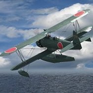
I haven't posted much on this one, but I've been working on it.
- 14 replies
-
- 13
-

-
Yup, it's nice to see someone with an imagination.
-
Yup. You're correct, Mike. I was just sort of wondering out loud. It seemed like quite a few. I've bought some of the damaged box kits in the past and have had the impression that those were single kits that were damaged because the offer had disappeared right away. Of course, perhaps there were other folks buying at the same time too and it just seemed that way. I've not built any of those kits yet, but I usually inspect them. I bought the 1/72 Hasegawa B-47 kit that was offered too.
-
Hmmm, I wonder how many were damaged, I got one too.
-
An interesting find in what feels to be the middle of no where
denders replied to denders's topic in General Discussion
Interesting, I wonder how it got there. And if the crew ejected and it crashed in the UK, it doesn't look 'crashed' or 'destroyed' from what I could see. -
Thanks, it's getting there. I'll be back on it this week. We spent last week at the NC Shore with friends.
-
We were at the NC shore, North Topsail. So, we made a trip to Jacksonville, NC. There's a nice smallish hobby shop there. I wish we had something like that in the Nashville area. The ladies also wanted to go to Hobby Lobby too. So, I picked this up at Hobby Chest of Jacksonville. I need to figure out whether and when this model of the Tomcat flew from Nimitz and then find decals. And since Hobby Lobby had a 40% off boxed kits, I picked this up. It's a little larger than the previous Gundam. 1/144 to 1/100.
-
We spent last week at the NC shore. To get there requires two lane roads and winding to and fro. No interstate all the way. This is Maple Hill, NC. There's a windsock and if you look on google maps, it's a small grass strip. To me, the curiosity isn't the Ercoupe, but what looks like a Jet Provost (???). What's it doing there? My impression is that it would take more runway than is at this location. And probably hard surface too. I think it is the aircraft that shows up on google maps, but it's been moved. Of course, the Ercoupe does hold interest because a long time ago, one of my uncles was partners with another fellow in an Ercoupe. I don't know if it was before the war or after. My father had mentioned that he had had at least one ride in the Ercoupe and I have a slide with Uncle's aircraft. It wasn't painted as fancy as this one, just all over silver with what looks like a black stripe or some sort of spear. My understanding is that Uncle had his license, but the other fellow didn't. I've no idea whether that fellow was working on his license. But, one day he decided to go flying and flew it into a row of trees.
-
Looking good from here, Chris!
-
I have always been glad that no one has made a 1/24 Corsair. That way I didn't have to decide whether I would buy it.
-
Thanks, Quint. That's what I went with. Working on decals. The red fin-cap is painted.
- 71 replies
-
- 10
-
-
Where can I get revue and correction for the 1/32 Revell Fokker DVII
denders replied to Sukhoi's topic in LSP Discussion
Well, you've dug up a 16-year-old thread that has scans of a 25-year-old magazine article that are a bit pixelated and probably couldn't be read very well 16 years ago. I can't read the dimensions either. You could be patient and perhaps someone here has that magazine and might help you out. I don't have any of the old FSMs, I may have had it but all of that was disposed of at least 10 years ago. You could also be patient and see if someone offers that magazine at a lower price too. Sorry. I find it interesting that the article appears to have been written by a gentleman who passed mid-October. -
Thanks, Ben. Good to know I’m the only one with big thumbs. They’re from GT Resin.
-
Okay, working on the landing gear. The light gray gear on the left is the kit gear. The gear on the right is the 3D printed AM gear. The kit gear aren't really too bad. There is some nice detail and could be made to look as good as the AM gear with a little bit of work. The AM gear has some extra levers and lines. Some of which I messed up cutting off the 3D printing supports. Some sort of picture with them highlighting what to keep would of course be helpful. I have the AM mains turned the opposite of the kit mains, so you can't see that the loops for tying down the aircraft aren't there. They were until my big thumb pressed on them and broke them off while test fitting the main gear in the aircraft wheel wells. I've already shaped some brass wire to replace them. Next, the wheels. The wheels on the left (light gray) are from the AM landing gear set. The wheels and tires in the middle are the kit wheels and the nose wheels and mains tires on the right are the Z-M AM "flattened" or perhaps "pre-loaded" set. Personally, I like the Z-M parts. It's up to you whether you like the pre-loaded type or not. The kit supplied parts are plastic and the AM stuff is resin, whether 3D printed or cast. Now to do some research and decide which parts I'm going to use. Dave
-
Those look nice!
-
Thanks, guys! And thanks for the info Jens. Since it is the first Z-M kit and I had also purchased some AM for it, I've ended up just following the kit build pretty much (except the cockpit.) I have quite a few of the other Z-M F-4 kits in my stash. I will do some additional research while building those. I think it is a nicely detailed kit. Dave
-
Don, the wire wheels are in the kit too.
-
Thanks, Quint! It obviously didn't take a week to remove the masking, but......... I kinda feel like some of the colors are a bit too dark. All the metallics are MRP. Next engine nozzles and landing gear.
- 71 replies
-
- 13
-
-
All the painting around the aft engine area is done, except for the nozzles. I feel like it will take a week to get all the masking off.
- 71 replies
-
- 12
-
-
My grandsons gifted me this kit last Christmas. This kit has loads of hotrod parts in it. The color is Tamiya Lacquer Mica Red. I'm not getting into detailing it because it will most likely become a long-term Christmas decoration.
- 14 replies
-
- 15
-
-
Working on all the metallic colors at the aft end. Masking then more masking then more masking...........................
-
So, finally got the flag decals, now I'll have to work on that on the Pharris. I'm planning on having the rearmost hangar bay doors of Nimitz open on each side. While I'm not going to light the hangar bay, I wanted to have aircraft there to see when peering through. So, I'm building aircraft now, so I have the aircraft to put in the hangar deck before I put the flight deck on. Lots more tiny pieces. I've only started on the F-14s. Then there are A-7Es, A-6Es/KA-6Ds, E-2Cs, EA-6Bs, SH-3Hs, S-3As, and EA-3Bs. Most of the F-14s with wings spread will probably not be used.
-
He had a big 'sale' recently and I saw that he posted to let everyone know that he's working on fulfilling all the orders. I got the idea that he was swamped. That may have been a week or so ago, I don't remember exactly. I also saw him post about a passport problem related to him being at Scale Model World too. He was at the USA-NATS in July.
-
Masked it up last evening and painted the Medium Gunship Gray today. Still lots to do yet.
- 71 replies
-
- 15
-
-
After some seam corrections, the second gray is on.

