
tomprobert
-
Posts
1,501 -
Joined
-
Last visited
-
Days Won
24
Content Type
Profiles
Forums
Events
Everything posted by tomprobert
-
That’s outstanding. Being a regular vac builder myself, I know the work that’s gone into this - and what a result. Tom
-
Really pleased to see this release - I personally love the F-35 in all its forms and can see a 617 Squadron build in my near future.
-
 Fantastic. I love projects such as these - proper old-skool. I always find transparencies on these types of kit the biggest headache but I’ve never tackled something with so much glass… I wonder if it may have been easier to have the entire forward section made from clear plastic but you’d still have a major join down the centre of the windscreen to deal with. I’m looking forward to more updates as they come - and good luck! Tom
 -
Blimey, your progress with this is really rapid - and of the utmost quality!
-
You should be really pleased with how this has come out, Kev - it looks like you’ve used a high-end mainstream injection kit rather than a complex conversion which is huge kudos to your skills. I love the finish too - spot on for a ‘warbird’ and seeing these regularly at shows in the UK I’d say you’ve got it spot on. Tom
-
After a glorious week skiing in the Dolomites of Northern Italy, I returned and tentatively opened the attic to see if the Stirling was still standing on her new legs… …and thankfully she was! The undercarriage hadn’t budged even a fraction of a millimetre so I’m calling it a success. I’ve added a few more bits of the main structure from more spare sprue: Now it’ll be the long task of making and adding the many other details to really bring these to life. Saying that, I’m off to France for a week now so actually it’s heading back into the loft for the time being! Tom
-
Yes indeed, Derek - all the joints etc will be made from plastic card and bits of sprue and the like. Once the main structure is done, it’ll be a long process of adding the finer details.
-
Thanks, Kev - and yes, the cross beam is Evergreen but is purely cosmetic - the gear doors will hang from here in due course. I've also got the foam at the ready! Thanks, Paul - when it's broken down it's actually quite a simple design. Keeping it all together is the issue! I'm really hoping I won't have to use brass as I have never done anything like that before and doing something as complex as this for my first try will be a big ask. However, if it's still standing good this time next week I'll stick with the plastic gear. We shall see.
-
Well… progress has slowed a little of late due to work, but I’ve made a tentative start on the very complex landing gear. This is a bit of an experiment, if I’m being totally honest, as I’ve knocked up some gear using spare sprue. I’ve no clue about working with metal or solder, so this may (literally) fall flat on its face, but we’ll see. I always keep large sprue trees as it’s so useful when it comes to scratch work. I’ve chosen some that’s a little thicker (by 0.25mm) than the HK Lancaster gear legs as my logic is if such diameter can support the heavier weight of that kit, it should be able to hold the much lighter vacform Stirling. So… some sprue and lots of small metal pins which will be used to reinforce each join: Following plans, I cut the main parts of the structure and these were then slowly put together. CA glue secured the metal pins in pre-drilled holes, and then when each ‘leg’ was complete TET was run into each join and allowed to dry for 24hrs to make a very strong join: Great care was taken to ensure each part of the gear was identical: The joins were then reinforced further with Milliput and sanded smooth: Next, the main cross members were added using more sprue and again strengthened with metal pins: And with the wheels added, they are starting to resemble the complex structure of the real thing: What I’m now going to do is temporarily fix the gear to the bays and leave it standing for a week. I’m off to Italy skiing so when I return, if the model is still standing securely on its gear I can call this a victory and crack on making and adding the rest of the detail - of which there is lots! If not, and I come back and it’s laying flat on its belly, it’ll be back to the drawing board and I may have to invest in a soldering kit and a whole lot of reading… Stay tuned! Tom
-
Wow. And as Forrest Gump often said… “that’s all there is to say about thaaaat.” Simply superb. Tom
-
Phew! I’m sure there was a sharp intake of breath as you prized open the box! I am really looking forward to seeing you resume work in this - when you’re settled - as are many others. I need my “Craig’s masterclass in building B-17s” fix All the best, Tom
- 1,582 replies
-
- 1
-

-
- 3d printing
- hk models b-17
- (and 4 more)
-
We’re a patient bunch, Kev. Take your time and get it right. It’s great to see you back at the bench! Tom
-
Oh God yes! The thought of making it be able to adequately support the model's weight is enough of a headache alone!
-
You’re right, Derek. The undercarriage was so high because early tests using a half-scale model showed the take off run was very long. The proposed solution was to increase the wings’ angle of incidence by 3 degrees. However, the tooling had already been made and the prototypes under construction, so the easier and cheaper solution was to lengthen the gear legs. As we all know - it was prone to collapse and even the first flight of the prototype ended in a gear collapse and a write off of the airframe!
-
Thanks for the kind words, chaps I subscribe to Air Modeller so have all of the Stirling articles you mention - they have already been an invaluable resource. I've also found some really interesting clips on YouTube about the landing gear for those that are interested: It's going to be a nightmare of epic proportions making this!!! Tom
-
Thanks, chaps - the landing gear is certainly going to be the most challenging part of this build. Speaking of which, I thought I’d start with something relatively straightforward as a first, tentative step. When I inherited Cees’ parts he kindly threw in some spare HK Lancaster wheels which has been most helpful. The Stirling and Lancaster shared the same hub, but the Stirling’s tyre was larger. Plans consulted, I came up with a cunning plan… First up, I used some Evergreen block strip of the correct size to enlarge the Lancaster tyre to the correct diameter. Using strip, rather than a sheet of plastic card, means they follow the contours of the tyre well and reduce the amount of sanding needed later. Here you can see the modified wheels with the strip added: Next, I used some tape to protect the hubs, and layered on some P38. The rear-most tyre has already begun the sanding to shape: Both tyres sanded: And then primed: Not bad - although the shoulders need rounding off a little more. A job for another day. Until next time, Tom
-
I think John Wilkes (aka Tigger) has the molds for the clear cockpit piece. I may be worth dropping him a line and seeing if he can run you off a copy..?
-
I think you're doing yourself an injustice here, Chris - seeing your Orion and Hudson you more than the necessary skills.
-
Very kind, Andy - thank you! These builds usually take around 2 years on and off, but if recent progress is anything to go by this one might be ready for Telford this year. However, I do like to hop around from build to build, so no promises! Many thanks, Craig! The blue background is actually poster paper we use at school for backing out display boards. One of the perks of being a teacher - unlimited supplies of sellotape, pritt-stick and paper! But… shhhhh…
-
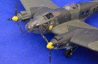
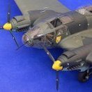
Greetings all More progress to update you on with the Super-size-Stirling! Since the last update the wings have been glued into place and the joins with the fuselage made good. Due to some careful planning in regard to the the spars and mating surfaces, very little filler was actually required which was a bonus. Next up I thought it made sense to tackle the fin and stabilisers as then the model will be structurally complete and the major sanding and preparing of parts will be completed. The kit parts are pretty basic but the shapes are good: Each part was scribed after careful consultation of plans. I concentrated initially on the fin - it was sanded to the correct depth and then I epoxied a wooden dowel more or less along the rudder hinge-line to act as a spar and strong attachment point to the fuselage: After more checking of plans a hole was then drilled into the top of the fuselage for the dowel to pass through and into the top of the spar-box I'd made for the stabilisers, meaning a very solid join. This is not the case with the real aircraft I hasten to add (there are very beefy rear fuselage frames that support the fin) but none of this is visible on the model so I went for strength over accuracy: With the fin set and filled, I then turned my attention to the stabilisers. Stirlings are more often than not seen with the elevators in a drooped position when at rest, so I thought it best to do the same with mine. First I removed the elevators from the stabilisers: And then glued some thick plastic card along the hinge-line to blank off the rear of the stab and also act as a spar: More dowel was then run through the rear fuselage: And then the stabilisers we epoxied in place, with the dowel butting up against the rear spar of the stabs making a very strong join. I made a rudimentary jig on the kitchen table with pots of paint and bits and bobs (nothing too technical in this house of mine!) to ensure everything was good and true: The small protrusions on the rear of the fuselage was different shapes on either side, and one slightly higher on the fuselage than the other, so lots of P38 was used to correct the shapes and help align everything properly: When all the filling, sanding and rescribing was done - and a splash of primer applied - everything came out ok: Deciding to have the flaps dropped meant the gaping hole along the rear of the wing needed addressing. This is curved metal skin, upon which flap tracks run on the real thing. There are also some fuel cells visible, but my skills don't stretch that far and neither to have the inclination when so little will be seen when the flaps are in place. The solution to making this was remarkably simple - I just cut some thin plastic card to the approximate shape and glued it to the lower wing skin, allowed this to set and then gently bent it to shape and aligning it with the upper surfaces. This was then clamped whilst everything dried: And when dry it was trimmed to the correct shape, primed and... success! When it comes to making and adding the flaps themselves, the flap tracks etc. will be added then. I have also removed the opening for the front turret: I am not completely convinced the shape is exactly correct yet - the nose may be a smidge too wide - but I'm going to leave this for a bit and see if any further remedial work will be needed whilst i get used to the new nose profile. So that brings you up to speed - something resembling a Stirling is slowly emerging from some bumps in plastic so I must be doing something right! As always, thanks for stopping by. Until next time, Tom
-
Room is now at a critical point, Derek. I’m going to have to sacrifice a large built up model to accommodate this one, and it will be the Hobby Boss B-24D which I am likely to donate to the fantastic museum at Old Buckenham. The curator, Jim, is a great guy doing some fantastic stuff and is slowly building up a great tribute to the USAAF crews based there during WWII. I’ve already given him a couple of 1/48th B-17s, but being a B-24 base I think a large Liberator is needed! At least it’ll be on display rather than hidden away in my loft where no one sees it - and I’ll make room for the Stirling!
-
1/32 Matchbox PK-505 Tiger Moth Floatplane G-AIVW
tomprobert replied to Archimedes's topic in Works in Progress
Good to see some progress on this build. Love the old school engineering going into this - great stuff. -
Astonishing. We need a glamour-shot of her sitting on her dainty legs
-
But Jay... you operate in a different league. I'm just cutting and sticking bits of plastic - you magicians who work with metal have a totally different skill-set and one I'm sure many aspire to... me included!
-
Afternoon all, I've really had the wind in my sails with the big Stirling this week - having a week off of work has meant some additional bench time and this build has motored along. With the interior painted, I could join the fuselage halves together - the fit was pretty good and the interior bracing and bulkheads I'd made meant everything aligned as it should. With the joints glued and set I removed the opening for the mid-upper turret, and used plastic card to blank off the kit wing-roots which are incorrectly positioned: All the joints then got a coat of P38 car body filler, and were then sanded smooth. With this done, scribing could begin. I'm often asked about the tricks of scribing kits such as this, and the truth is it's very simple. Using plans as a guide and some dymo-tape, panel lines are instated with a Bare Metal Foil Co. scriber and then sanded smooth with some fine sand paper. This allows the curves of the fuselage to be done as well as the straight, flat panel joints. The whole fuselage on this only took an evening: These pictures show the finished fuselage - although being white my handiwork with the scribing doesn't show up at all well. Note also I've now added the wing spars: So now it's time to start thinking about adding the wings - they will slide nicely over the spars which interlock with the interior structure I made previously: The wings are just resting in the following two shots and the correct dihedral not set, but it gives an idea about the overall shape: As you can see, she's a big old brute. And once again, the wife isn't impressed - but nothing new there... The next task will be adding the wings and making the joints good - with the classroom beckoning again tomorrow things will slow a little again but I'll update this when there's some more progress to report. Cheers, Tom

