
ChuckD
-
Posts
1,023 -
Joined
-
Last visited
-
Days Won
10
Content Type
Profiles
Forums
Events
Everything posted by ChuckD
-
Thank you, all. Much appreciated. @mc65, I wasn't aware of that Airfix set and will look into it. Figures add so much to a model and are almost a necessity for any diorama. However, it gets really frustrating trying to find ones that will fit the scenes in my head, so that's why I started sculpting a few things here and there. The problem for me is compounded by the fact that I tend to do a lot of Pacific settings which makes it that much harder to find figures that both physically fit and are clad in theater-correct attire. Take, for example, the figure I had to use for our intrepid pilot, Lt. Ray. The figure is designed for the ETO and thus, if you're really looking, you'll see he's wearing heavier gear than what would be found in the SW Pacific theater. So, sadly, I'm left to either eschew perfection and accept a little artistic license, or sculpt the entire figure, clothes, headgear, harnesses, straps, equipment, and all from scratch. Maybe some day I'll have the wherewithal to do that, but not yet, so sanity dictates I choose the former option and not the latter. I offer my sincerest apologies to those who are offended by my lack of accuracy. What I'd love - and might push me to start sculpting more - is a posable mannequin in 1/32 scale that I could use as the base frame for the figure. I've tried doing a base frame from wire before and it went poorly. So, if any of you out there have any leads for something like that, I'm all ears. Anyway, I spent a little time at the bench today getting the arms done for the crew chief. I'm very happy with how they turned out. Tomorrow, I'll add pockets, arm patches, and take a swipe at the collar. This is my first time using Green Stuff vs ApoxieSculpt or Magic Sculpt. I am enjoying working with it as it is stickier (thus it doesn't slough off the wire frame if I push too hard) and it's a harder material once mixed, meaning that I can push hard while sculpting and already-completed details aren't destroyed elsewhere. As with any epoxy putty though, the build process is agonizingly long as it typically has to cure for many hours before you can progress to the next section.
- 143 replies
-
- 10
-

-
Tom, I'm sorry I missed this post! I really enjoy your work and your thorough breakdown of the process. This will come in handy when I decide to tackle the ZM Butcher Bird.
-
Thank you! I'm glad to know it wasn't operator error. Anyway, good progress today. After sifting through my spares bins, these were the two best candidates for the lower half of the crew chief. The left is the standing pilot figure from this Corsair kit. The right is a 1/35 scale Wehrmacht Nashorn gunner figure also from Tamiya. Curiously, they're identical in dimensions despite the difference in scale. In the end, I opted for the standing pilot figure and began scraping off details that I wouldn't need. This is after getting the torso down to almost nothing and adding the wires for the arms. Front: Back: Here is the basic jacket sculpted with Green Stuff. The hands are from a 1/35 set of heads and hands from Hornet. Again, despite the "smaller" scale, they look a little large, but I'm hoping that will become less obvious after the arms are fully sculpted. I'll also be adding some pockets and such to the jacket once the base material cures. The back is okay. After this photo, I went back and did a little more detailing, so it looks a little better. I'll bend the arms into the proper position before adding the sleeves and such. I also filled the gaps in the pilot figure, including the gaps between the parachute and the figure itself. I suspect I'll have some cleanup to do once I can get some primer down, but so far, I'm happy with the results. While waiting for the epoxy putty to cure, I decided to build the Anyz Models canopy rail. Unfortunately, I hacked off the mounting brackets for the mirrors while I was removing the frame from the 3D printing supports, so I had to fabricate absolutely tiny new ones from wire. Not perfect, but if they all hold together until final assembly, I'll be very happy. Lastly, I took the time to mask all the clear parts as well, so I'm getting close. I hope to finish up the figure sculpting tomorrow, then start the final prep for painting on those. After that, I'll start focusing on the groundwork.
- 143 replies
-
- 20
-
-
I could, sure. But look at the source images on the first page of this thread. The pilot is entering from the left side.
-
Ha! Yeah, Mike. It pretty much builds itself from here. Thank you! I wasn't aware of that. I'll stick with him getting in from the left so it lines up better with the source material.
-
Hi, all. Back with an update after making good progress today. First, our gallant protagonist has been roughed in. Surprisingly, the Black Dog resin figure fit the scene pretty well. I will only have to do some minor shaping and filling behind the left shoulder to clean him up. I'll need to fix his fingers as they broke when I tried to straighten them a bit, but that shouldn't be too big of a problem. I'm going to have to deviate from the source photo just a bit here as the parachute is going to cause a bit of an issue. In the reference photo, I believe Lt. Ray had his parachute pack on the seat pan with the straps splayed out the cockpit and down the side of the fuselage. On the figure set, the parachute pack (not attached) is integral to the figure and all the associate straps and harnesses are already molded onto the figure. I don't think I've got it in me to remove all the molded detail then sculpt in other detail that would inevitably be needed after such a task. So, in our version of history, Lt. Ray will be entering the a/c with his pack on his rear. Artistic license, etc, etc, etc. When I got to looking at the second figure - the one that I need to sculpt from the waist up - I realized he was standing on the section of wing outboard of the fold line. So, I needed to build the wings. After that, I was so close to being done, I decided to finish it up. So, aside from some clear bits, antennae, a pitot tube, and the Anyz Model canopy rail, the build is more or less done. All the gear stuff is dry fit, including the doors. Same for the prop. As others have said, this is a wonderful kit. The engineering on it is just superb and it really went together well. The only fit issues I have are near the top of the cowling, so, I'll need to do a little filling there. But, outside of that, it was a good clean build and I'm glad I've got another in the stash. That's not to say I missed any opportunities to shoot myself in the foot... I forgot to add the little clear windows on the leading edges for the gun cams and such. I didn't realize it until I'd almost closed up the small panels on the top of the wing above them. Fortunately, by reaching into the small panel on the top of the wing, I was able to finagle the two clear pieces in place without too much trouble. Story of my life. Anyhoo, I hope to make some progress on the figures and the base now. The build work will be halted until those have been addressed. Again, I don't want to paint and finish the airplane, as I just know I will run out of steam if I save the figures for last.
- 143 replies
-
- 18
-
-
Tamiya F4U-1 in flight, VMF 213 Guadalcanal
ChuckD replied to Bstarr3's topic in Ready for Inspection
Wonderful result! Nice work! -
Progress! wheel wells and wing roots are dine. No weathering yet, but a base coat is down. No warranties express or implied on spelling, grammar, or diction due to wine consumption. 8|
- 143 replies
-
- 18
-
-
Absolutely awesome!
-
Hi, all. Back with a small update. Progress has been kinda slow this week as I've been busy with work, stuff with my kiddo, and I've been under the weather. I think for the diorama, I'm not going to attach the a/c to the base. The odds of the dio traveling outside my model room (before it makes its final trip to the dumpster after I'm cold and in the dirt) is near zero, so it shouldn't much matter if the plane and base are detachable. With that in mind, I'm taking some time to detail things on the under side of the plane that would never be seen if attached to the base. The Corsair has quite a bit of plumbing running through the wheel wells, so I tried to simulate that here. I also opened the lightening holes on the bottom of the spar to run plumbing in there. I'm still searching for photos of the gear bay forward of the spar though. There has to be plumbing in there for the main hydraulic actuator and other sundries. So far, all the sources I've found have come up dry. I've got amazing photos of the bay aft of the spar (thank you again, @Dana Bell!), but the search continues for a good look forward of the spar. I had to add the door actuators so that I could plumb them properly without the doors being in place. Fortunately, the doors can be added after the fact with no issue. The only downside is that, until the gear is slotted in place, they become load bearing when the assembly is placed right side up. You can already see that the actuator on the right has started to weaken. It's amazing how helpful it is to use lead wire. It's so much more friendly to use than even soft copper or brass. Anyway, that's it for now. Next up will be a similar treatment to the other wheel well, then assembling the main gear. On the plus side, I just learned that my new company closes down over the holidays, so I get an unexpected paid week off between the holidays! With nothing else planned, that should allow for some pretty decent progress to wind out the year.
- 143 replies
-
- 25
-
-
Nichimo 1/20 Cessna 172 "Juliet" Scratchbuilt overhead console
ChuckD replied to Hawkwrench's topic in Works in Progress
What a cool build. I've often thought of recreating some of the chickenhawks I used to fly. Too bad this kit is so hard to find. Back when I was flying a lot, my FBO had a C-172N on the line (N6370D) that was just beat. Inside and outside, it was scratched, dented, cracked, and torn up. But man, did that airplane ever want to fly. It'd hop off the ground in a heartbeat, fly like a dream, and landed as smooth as glass. The line guys at the FBO started calling her "the hooker with a heart of gold." She wasn't much to look at, but she really knew her trade. -
Oh, I watched you work through that process. You deserve the highest commendation, but that's 100% more effort than I'd want to undertake. Just sell me a sprue, HKM.
-
I agree with all the sentiments above. I was jazzed about the A-26, but never bought one due to its many issues. The B-24's issues don't bother me as much, but I'm part way through the HB kit now and probably wouldn't bother with a new tool kit regardless of perfection. One massive Liberator is enough for me. Back on the topic of A-20s, it would be awesome if HKM came up with a way to combine the two kits so you could build a gunship with the individual exhaust cowls. I'd buy the G kit and a cowl sprue any day, but right now I don't see a way to build a G with the individual cowls without buying both kits and bashing them together.
-
Thanks, that's definitely a great mindset for this hobby. I like to think I strike a balance of detailing where it's visible vs time and effort wasted on something I'll never see. At least, I strike enough of a balance for my tastes and I respect everyone else's artistic license to detail as their heart guides too. For me, this hobby is the confluence of my passion for history and my desire to do things with my hands. It also satisfies an artistic creative drive too. So in the end, it's very cathartic for me. I took the week after Thanksgiving off and spent it in the model room listening to jazz and building away. As a bonus, I was, for the first time in 13 years, able to turn off notifications on my phone and ignore work emails. It was probably the the closest I have ever come to true zen enlightenment.
-
@Dana Bell I just received all three of your Corsair books yesterday. Thanks for the prompt shipping! What an awesome collection of resources for geeks like us. I found the color profile you mentioned, but wanted to say that some of the details shots of the gear bay are what I've found most helpful at the moment. Right now I'm trying to add wiring and other sundries to the gear bays. Do you (or anyone else) have good reference photos for the part of the gear bay forward of the spar? I think I have everything I need for the area aft of the spar, but references are short for the other area. Thanks!
-
Fascinating, thanks. I'll see if I can grab a copy of it. You know, if this turns out to be a presentable project when done, I'd be happy to give this to you as a direct descendant of the man being portrayed. I just don't know how I'd get it to you without UPS or the likes turning the whole thing into plastic kibble. Anyway, I couldn't stand the back of the cowl flaps being completely devoid of details and none of the aftermarket detail sets are in stock anywhere, so I added a little bit myself. It's not much, but it does add some visual interest behind the flaps. As it stands, I currently have the tailwheel, cowls, and engine installed and am working on the lower wings. I'll be adding some wiring to the gear bays to busy them up a bit.
- 143 replies
-
- 19
-
-
Once I finish my Corsair build, I'll jump in on this.
-
Sweet merciful God, please don't connect that to the Internet.
-
Another Public "Thank You!" to Sprue Brothers
ChuckD replied to mywifehatesmodels's topic in General Discussion
I echo these sentiments verbatim. They're always my first stop for model stuff. I shudder to think how much money I've sent them in the last decade. -
It can't be terrible if it's right.
-
I read that he was one of the few people whose health improved while in a POW camp.
-
Following and looking forward to seeing it!
-
I got a good chuckle out of this, thank you. The line on his note is something of an inside joke, but rest assured, he's a pretty awesome kid and he got his cake.
-
Thanks, Dana. I appreciate the compliments and the clarity. Which Corsair book are you referring to? The rivet counter one or the aircraft pictorial one? Disregard, I just ordered all three off Amazon.
-
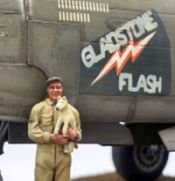
Thanks for sharing. If you think of the name of Bruce Campbell's book, let me know. I'd like to learn more. It is my impression too that, with the shoestring nature of the campaigns in the SW Pac, the pilots often flew whatever ship was available. Certainly some guys had assigned or "owned" planes, but my impression is that was the exception, rather than the rule. Well, let's talk about that. Obviously, the colorized photo shows it in the early 2-tone scheme. The profile for it in Michael Claringbould's Pacific Profiles book also shows it as a 2-tone bird. My thought process was that, being an early ship in a training squadron, it was probably rotated to the training role once it was so weary as to not be useful in frontline service. Thus, it would likely still be in its original 2-tone camo scheme. However, in looking at the photos, I can definitely seen an argument that it is a 3-tone scheme with straight camo lines running along the longitudinal axis of the a/c with the demarcation between the dark blue and medium blue along the upper edge of the bar in the insignia. What's the consensus here? Upon further research it appears there likely will be no consensus. Many forum posts here and elsewhere with @Dana Bell's input lead me to believe this would be the 3 tone camo.

