
ChuckD
-
Posts
914 -
Joined
-
Last visited
-
Days Won
9
Content Type
Profiles
Forums
Events
Everything posted by ChuckD
-
P-38G Old Ironsides in Guadalcanal: The patient has pulled through!
ChuckD replied to ChuckD's topic in Ready for Inspection
Thanks, Tim! I tend to ogle it a bit as it sits on the shelf too. Thanks for the encouragement, I likely wouldn't have done it otherwise. -
P-38G Old Ironsides in Guadalcanal: The patient has pulled through!
ChuckD replied to ChuckD's topic in Ready for Inspection
Looks great. Thanks, Ray! -
Restoration of P-47 named Bonnie finally finished
ChuckD replied to Oldbaldguy's topic in Aviation Discussion & Research
Here are a few photos I snapped of it at Oshkosh last week. Beautiful aircraft. I'm unclear though, is this airframes the actual Bonnie, or another airframe painted to play the part. -
It was miserably hot and I think it negatively affected turnout. By Thursday, aircraft attendance was relatively low.
-
So, after much searching, I think I've finally narrowed the build down to this scheme: STINKY, a 3rd BG/12 BS A-20G-30-DO seems to check all the boxes. I've got a couple pictures of it, the nose art and decals will be achievable without too much trouble, and, most importantly, it has the right cowls. The trouble in recreating this specific airframe would appear to be the external bomb racks. I've posted the thread below to cast a wider net, but does anyone have any sources for a set of external racks? I dug through my Trumpeter Dauntless kit to see if I could pilfer the wing racks from that, as I figured they were fairly generic parts, but they are not.
- 163 replies
-
- 10
-

-
Hi, all. Subject pretty much says it all, but for specificity, I'm looking for external bomb racks as would be used in this picture. I don't pretend to be an expert on external bomb racks for A-20s, and I understand that there may have been a couple different types used, so I'm not sure which would be correct, but I'm guessing it's of this variety: Does anyone know of a source for these in 1/32 scale? If not, does anyone have drawings for these so that I can try to fab them up from styrene?
-
1/32 Douglas TBD-1 Devastator by Trumpeter - TBD-1A in October 2023!
ChuckD replied to Kagemusha's topic in LSP Discussion
That looks incredible. I will be picking that up for my build. -
Hi, all. Just another quick update during my busy schedule. I'm hoping things slow down a bit in the next couple weeks so that I can get some bench time. But, it's been a busy place here and likely will be for another week or two. Also, I've been kinda intentionally slowing down on the build because I was waiting for this... I received my review copy of these today and to say I'm beyond pleased is an understatement. If you've used Eduard's Brassin or wheel sets in the past, you'll know how good they are and these are no exception. The kit wheels (shown later) were referenced from a modern restoration aircraft, so the wheels and tires are nowhere near correct for a WWII aircraft. So, if you're doing a WWII model - and few A-20's saw service outside that period - these are a must have. In the typical sturdy, well-packed box you get a number of goodies. Here's the overview: The mask sets are cut neatly from thin yellow tape sheets, similar to Tamiya tape. The instructions, as always, are clear and well illustrated. Note the different symbols denoting replaced parts as well as the option for including a hubcap as needed for your build Now, the part you all really wanted to see. Here you can see the mains. Their diamond/crosshatched treads are crisp and clean - to the point where I might hit them with a sanding sponge to soften the sharp edges up a bit. The manufacturers markings throughout all the resin pieces are super crisp too. I also appreciate that they have small pour stubs that don't wrap around the sides of the tires like many other sets do. Those always require awkward cleanup while these should be a snap. Now the nosewheel. It was slick with no tread, but the detail of the markings is laser sharp. The PE hub caps are also included and feature very small attachment points which promise a very easy cleanup. This was interesting to me. I've used a number of Eduard wheel sets before and the hubs themselves have always been of poured resin. While that worked fine, there was always a ton of flash to clean up in the holes around the spokes. Here, Eduard has switched to 3D printing and the detail is outstanding. The mounting pads for the hub caps are super crisp. The back side will require the removal of a number of small supports, but a thin razor saw should do the trick without an issue. I'll report on cleanup later. Here you can see the difference between the Eduard and kit wheels. The Eduard set is about 2-3mm wider in diameter than the kit wheels. There's a little bit more detail to the inner hub on the kit pieces, but none of that will ever be seen anyway and the resin pieces have the detail where it matters. The smooth tread of the resto/warbird wheels vs the crosshatch of the wartime tread. Comparing these two, the kit tire (likely a faithful reproduction of what was actually on the reference aircraft at the time) looks like something you'd see on a camper trailer. The Eduard kit blows it out of the water. In the end, while I did receive a copy of these gratis for review purposes, I can't recommend them highly enough. If I end up doing another HKM A-20 kit, these are a no-brainer and will be part of the build without question. These should be hitting our favorite retail haunts within the next few weeks, give your A-20 some love and get her a new pair of kicks. That's all I've got for today. I likely won't be able to update for another week or two as I've got quite a few things coming up on my calendar. But I'll be back soon and we'll get this bird across the finish line.
- 163 replies
-
- 28
-
-
Definitely. I was burned by the Infinity Helldiver, so was going to hold off on this, but positive reviews and its pending status as vaporware pushed me over the edge.
-
Update: SB shipped my Val kit today. Looks like it must be in stock.
-
1/32 Douglas TBD-1 Devastator by Trumpeter - TBD-1A in October 2023!
ChuckD replied to Kagemusha's topic in LSP Discussion
As excited as I am to get into this kit, it's one of those that I think I'll wait for the aftermarket to populate a bit. -
I sure hope so, but I've not heard anything about it. It would seem like a decently easy thing to 3D print if someone has the drawings. The cowl ring would need to be replaced too, as the contours of the flaps are different as well. The kit's flaps contour around the exhaust pipes, while the earlier cowl model had flat flaps all the way around.
-
They backordered mine too, but said they were expecting them Friday. SB doesn't typically do backorders (as far as I know), so I assume they're only doing this because they expect them to show up soon.
-
Hello, all. Back with another quick update. Today we reached a new milestone by making the wings permanent. Technically, I'm only halfway there (insert Bon Jovi reference here) as I have only glued the top join of the wing. Using Tamiya extra thin, I ran a bead along each upper wing root (individually) and gently held the wing level with the root stub. This approach left a very clean upper join... ... The bottom however has a gap of maybe a half mm or so. There's enough give in the lower wing such that I think I can run a bead of ultra thin CA glue and get it to line up okay. I will wait till tomorrow to try it in order to give the Tamiya cement time to harden. I don't want to wrench on the lower wing and muck up the upper join. If you're in the "close enough" camp, the locking wing provides a decent fit without any glue. In all, the wing fit is a really solid piece of engineering. I hope to wrap up the remainder of the bills this week and get a little paint on it before the end of the weekend. My next week is nuts, so progress will continue to remain pokey.
- 163 replies
-
- 21
-
-
Yyyyyyyyyyyyyup. Does it show?
-
Wow, that's looking great!
-
Hello, all. Just a couple quick updates tonight. Been busy for the last week or so, and my schedule doesn't show any signs of slowing down, so updates will take a bit longer for the time being. Anyway, the props went together just fine. The blades are keyed to the hub, but it's a small key and one can still install the blades upside down. So, go carefully there. I used the UMM Propmaster jig for the first time and it was handy here, but not required. Here you can see the areas that required filling with epoxy putty. I shot it all with primer after these photos and cleaned up a few of the rougher spots. I'll prime again next and, if all looks good glue the wings on! Here's a neat little trick for masking round engines while still being able to reach the inner edges of the cowl with paint. Take a circle template and cut a paper circle just larger than the opening of the cowl. I used the 1 3/8" template here. Cut a small X in the center and extend one leg of the X all the way to the edge of the circle. Wiggle into place around the prop shaft, overlapping the cut to achieve perfect fit. More to come soon.
- 163 replies
-
- 30
-
-
I'd be very hard pressed to believe they're not aware of how things go together on the right engine. Maybe I'm naive to the world of injection molded model engineering, but wouldn't they have built a bunch of test kits during the QA processes?
-
Well, that's comforting in any case. Glad it wasn't the most common problem - operator error. What a strange engineering choice.
-
Thank you for the compliment. Yes, I believe L21 would very much benefit from being a handed piece, especially because it is keyed to the nacelle. But, it's definitely not... So the left side slid right on (once I figured out the cowling issue) and the right was stuck at about the 2/3rds mark. Please update with what you find.
-
Okay, this is what I was talking about with the right engine. The only way the firewall part can slot into the nacelle is at a decent rotational angle. See here: When I tried to put the engine on, I got to about here before *something* interfered and things came to a halt. It looked like one side of the cowl was hitting the bottom of the wing due to the rotated angle of the engine. It was clear, however, that the keying of the stub on the firewall piece was preventing the rotation of the engine to the point where it would fit nicely. Sooooo, channeling the subtlety that embodied my recent P-38 build, I got out my trusty exacto blade and made a minor adjustment. Aaaand.... Ta da! Way more better. I don't know... I don't *think* this one is on me. I think I got all the right parts in the right places, so I'm very curious to hear the progress and experience of others as they move through the engine install. Last night I finally fit the control surfaces and they went on without fuss. I also finished the exhaust on the right engine and then glued both engines to the wing. Once I get the cowl/wing/nacelle joins cleaned up, I'll glue on the wings, then it's off to the paint booth. Currently, with probably 90% of the parts in place, the nose sits firmly on the wheel, but there is not so much weight on the dime store nose gear assembly that it's at any real risk of falling on its tail. The only major assembly left to put in place that's aft of the CG is the turret, so I'm pretty confident it won't be a tail squatter.
- 163 replies
-
- 22
-
-

-
I, for one, welcome all models of A-20 Havoc/Boston. That said, I was in error and let my excitement get the best of me. The four "extra" pieces left over from assembling the left engine exhaust are actually used in the assembly of the right engine. There will be four left over pieces from the right. HKM made all varieties of exhaust pipe shape on both sprues. Sorry for the misinformation.
-
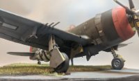
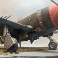
Following hot on the heels of my lighthearted sass above, it's time for another update. I spent quite a bit of time getting the two engines around last night and am almost done with them. As it stands now, the left is complete, but the right still needs the exhausts installed. I was so interested in answering the question about the cowls that I forgot to take pictures of the completed engine before I glued everything together. From the bottom of my heart: my bad. The left engine, tucked away safely in the correct cowling. The decal is a rando from the Airscale cockpit placard set that fit the pad for it. Here is the back of the engine with the Goldberg-esque exhaust stack setup. To HKM's credit, they did a very nice job in the instructions of making sense of the huge fustercluck that is the exhaustopus™. As you can see, I didn't paint the back of the engine as I have only so much sanity and precisely none of it will be visible once everything is together without a dental mirror and x-ray specs. As you can see, I did spray just a little black around exhaust stacks to begin the soot staining. Will it be visible once the whole thing is together? Probably not, but I slept better last night, so that's a win. Honestly, my recommendation for the exhaust stacks is to cut off the little locator pins that mate the pipe to its respective cylinder head. They don't always line up just how you want them and it's more of a pain than it's worth. I'd say I cut the locator pin off 1/3rd of stacks. I used thin liquid superglue to simply glue the exhaust stacks to the cowl flaps themselves. Seemed to work just fine and everything is nice and firm. The whole mess also fits nicely in the nacelle. See also: See also also: With engines dry fit, she's really starting to look the part. I did have to do some minor surgery to get the right engine to fit properly, but I'll post that in a subsequent update. Suffice to say the angle of the firewall part on L21 (mentioned extensively on the previous page) did, in fact, lead to some kookiness. We've talked at length about the cowling setup on this beast. I found this little tidbit to be very very interesting. Each L sprue (the engine sprue), of which there are two, has eighteen exhaust pipes for each fourteen cylinder engine. That says to me that they're already gearing up for the early style exhaust/cowl arrangement that has the stacks exiting the cowl individually, rather than through the cowl flaps.
- 163 replies
-
- 23
-
-

-
Decals schmecals. A laser printer and a mask cutter and we're off n runnin'.
-
Thanks, Kev! We didn't have much going on for the July 4th holiday weekend, so I've been afforded the opportunity to spend a good chunk of time at the bench. I'm back to work tomorrow, so I suspect the build will slow down pretty heavily after that. I've also decided that I'm going to wait for the Eduard wheel set to finish this off. So, I'll get as far as I can, but an RFI will wait till then. So, let's talk cowlings for a little bit. I tried really hard to keep the cowl assemblies separate and tracked as, out of aaaaaaaalll the itty bitty bits that make up the engines assemblies, the cowl and flap ring are the only handed parts. Yet alas, I ran into an issue. Let's explore. Here you can see the assembly for the left engine... ... and here the right. In either case, the cowl and flap ring (whether you choose the flaps-open or flaps-closed option) are individual components on the single M sprue. All other engine components are from the duplicated L sprue. The flap rings are keyed to their individual cowling, so it is (thankfully) impossible to swap rings between them. Once assembled, the engine is sandwiched between the cowl and flap ring parts, then the whole cowl-engine-ring sandwich gets installed on the firewall part L21 (which is a duplicate and the same on both sides as shown below). Note, that L21 is keyed to the stub on the nacelle by a flat spot at the 6 o'clock position. Likewise, the stub on L21 itself is keyed with a similar 6 o'clock flatspot. Left... Right. Sprue details from the instructions. What's interesting is that the nacelles themselves are, of course, handed, so L21 fits differently on both sides. Notice the slightly different rotational orientation of the cutouts at the top of L21 and the key on L21's stub. In both cases, there is a small shoulder cut on L21 that provides the real positive positional lock on the underside of the wing where it meets the nacelle. Once you have the grooves on L21 snugged into that corner, is pops perfectly flush against the face of the nacelle. So why does all that matter? Because the wrong cowl will just barely fit on the correct wing and will throw off the geometry of the engine assembly noticeably. Here you can see the proper alignment of the engine without the cowl. Note that we can (and did) draw a straight line from the carb intake on the wing to the bottom cylinder which passes through the keying notch in the baffle, rear upper cylinder, governor mount pad, prop shaft, and lower cylinder. Continuing that theme... With the correct cowl in place, that same straight line will pass through the split at the bottom of the cowling itself. The mating faces of the wing, cowling, and nacelles will also be nice and snug. Now, see what happens when we try to put the wrong cowl on the wing. You can see that the cowl is rotated a few degrees counter clockwise. Beyond the obvious problem of aesthetics, the real issue is that it you can force the wrong cowl to fit with the engine in place. Because of the keying of the engine baffle to the inside of the cowling, the engine will also end up rotated a few degrees counter clockwise with the cylinders and prop governor pad out of vertical alignment. But, with enough tape and some super glue, I could absolutely see myself not realizing my mistake until too late. As I said earlier - I really tried to keep the two cowlings separate so that I was sure I had the left cowl with the left wing and vice versa. But, when I went to test fit the engine & cowl on the left side with what I thought was the left cowl, I got the fit in the last photo. If I hadn't noticed that the cylinders were subtly out of alignment, I may have proceeded to make things permanent. The problems are compounded by the fact that with how the whole sandwich fits together, it's difficult to test fit without having at least the engine permanently together. I have no way of knowing now whether or not the parts are mis-numbered in the instructions or whether I, despite my best efforts, managed to swap them during the painting process. Occam's Razor says the latter is the most likely, but please use due care while putting your engines and cowlings together. If you have to use more force than you would expect, you probably have the wrong cowl.
- 163 replies
-
- 22
-