ChuckD
-
Posts
914 -
Joined
-
Last visited
-
Days Won
9
Content Type
Profiles
Forums
Events
Everything posted by ChuckD
-
 Some more progress today. The cheek gun panels went on just fine. A little filler and some light sanding to remove my fingerprints and it'll be just fine. Here you can see the gap between the nacelle and the wing root. A little filler was needed here too just to clean it up. The nacelle after the first round of sanding. I used a little Mr Surfacer 500 to fill a hole here and there on the nacelle joins. In all though, they went together flawlessly, especially considering how complex the join between the nacelle, the upper wing surface, and trailing edge pieces. These were later smoothed out scribed and re-riveted, so the wings are now done. After annealing the two PE armor panels, I installed them. Annealing is a must here - the PE is very stiff. I first tacked it in place with a little dab of CA glue. Then I took a glue looper and liquid CA glue and went around the piece tacking down each side until it was set all the way around. It conformed nicely to the curve of the fuselage and is nice and secure. Just go slowly here and anneal, anneal, anneal. I also finally got around to putting the gunsight and glass on. Looks pretty good if I do say so myself. Beyond that, I spent time getting the engines painted and prepped. I'll post pics when they're done, hopefully tomorrow. Keepin' on truckin'.
- 163 replies
-
- 27
-

-
Yeah, @CRAZY IVAN5 pics or it didn't happen.
-
Is that site broken for anyone else? None of the images load for me and most of the links lead to a page that says "oops, your site is not published." Thanks for the recommendation on the Roarin' 20's book. I'll probably pick that up. I did, however, just get my hands on the Legends of Warfare book yesterday and was a little underwhelmed. As I'm looking for historical photos of the A-20G in the Pacific, I was disappointed as there wasn't much of that content. Most of it focuses on its European use.
-
Damn the torpedoes broken nose gear! Full speed ahead! I've been making good headway over the past couple days and have not been as diligent as I should have been with posting pictures. So, let's play a little catch up. Using Magic Sculpt epoxy putty, I shored up the gaps in the nose panels a couple days ago and it turned out splendidly. You can see that I had also started the first round of sanding the seams. They were pretty minimal, all things considered. I'm going to try to highlight the areas I had to fill and sand so others can keep a sharp eye out for gaps. The trailing edge of the rudder had some gaps that I couldn't close while cementing, so it got filled and sanded. I might do a little more shaping to give it better taper towards the rear. A couple spots on the leading edge of the wing, but very very minimal. This tail plate was what gave me the most troubles. All 4 corners had to have some kind of filling. Though not terrible, they are in an awkward spot with tough geometry to work around. I highly recommend leaving off all 3 stabilizers until you're done sanding (AND HAVE THE DUMB WINGS ON SO YOU DON'T SNAP THE DUMB NOSE WHEEL OFF). A couple spots on the nose needed a little filler. I primarily used liquid sprue to fill these gaps, then Mr Surfacer 500 for any subsequent clean up. This gap panel at the bottom between the rear hatch and bomb bay was problematic and I saw it coming when I glued it together. No amount of finagling would get the two halves to sit evenly here, so there was a step between the two pieces. I sanded it as close as I could get, then filled with liquid sprue. Okay, so here's where I started to get myself in trouble. Again leave the tail stabilizers off until you've got the wings on. Reason being that without the wings, you can't really set the fuselage down without putting a heavy side load on the nose gear once the tail feathers are on. The fuse is off balance enough that it won't sit on a jig well and when you try to set it down on a flat surface, the leverage of the horizontal stabilizers combined with the weights in the model's nose, imparts a significant torque effect on the fuselage... and guess what little chintzy part is left to carry the load? See my previous post for a hint. So yeah, here's where we put the tail on. This is the bottom of the vertical stab. I had to scrape quite a bit of material off the bottom flange of the stab as well as the locating tab itself to get the stab to sit in its groove without rocking back and forth. I think the locating tab is just too long to fit the corresponding groove in the upper tail plate. So, without removing some material, it'll teeter totter back and forth with neither side achieving a good fit. However, this was an easy fix. Scrape a bit and you're good to go. The horizontal stabs benefitted from a little bit of sanding at their mating surfaces and with a combo of liquid super glue and some cement, they went on well. There was just a tiny gap that I had to fill with more epoxy putty. Mind the dihedral in the horizontal stabs. The A-20 had a pretty significant dihedral in the tail planes. The gaps... The tail more or less together. The control surfaces are still dry fit at this point. RIGHT HERE IS WHERE THE DUMB NOSE GEAR BROKE OFF. But, with copious amounts of liquid super glue, we recovered. And, as a bonus, we made other progress too. I spent the day painting the remaining interior parts like that pesky bulkhead that sits between the nose and fuse that forms the front of the nose wheel well. In doing so, that allowed me to install the nose. The final fit was pretty good. That little seam I had to sand on the forward bit of the fuse came back to bite me a bit as there is now a small - almost imperceptible - step between the nose and the forward fuselage. You can juuuuust make it out here. To be fair, I took great pains to try to show it off for you, but it's so small I think a quick swipe or two with a sanding stick on the nose ought to level things out just fine. The rest of the nose fit is just phenomenal. Great stuff. I'm really impressed. As mentioned, most of my day was spent painting and weathering the remaining interior bits which included the nacelles, landing gear, and gear doors. Again, I didn't photograph the progress, but rather just the more or less finished product. Here are the main gear and nacelle rooves on the bottom side of the wings. I added a couple brake lines (to be cut to length later) to spice things up a bit. It is surprisingly hard to find a good shot of landing gear plumbing on this thing. Here are the nacelles. You could lose your mind cleaning up ejector pins if you want, but they will be invisible anyway, so I didn't bother. Likewise, the nacelles are a wonderful canvas for super detailing if you see fit. I see that Eduard is planning a gear bay set, so I'm sure there'll be a lot of great details added here. Again, I dirtied these up pretty well as I figure the a/c in the SW Pacific weren't kept clean, and as anyone whose been in the gear well behind a radial engine can tell you... those areas get grubby. Once the nacelles are installed, this is just about the most you'll ever see - and this view isn't obscured by the landing gear mechanism. I glued the nacelles together then to the wing. All went together very nicely with a combo of liquid super glue and cement. The outer nacelle pieces on both sides needed to be pressed outward from inside then tacked in place with liquid super glue to mate to the channel wing channel without a gap. Again, the view once fully assembled. The other ancillary bits that I painted today: gear doors, inner flaps, bomb bay doors and associated mechanisms. Happily, once on her feet with the wings tacked in place, the nose gear holds up. I think HKM probably put just the bare minimum weight in the nose to guarantee the tail didn't fall, so hopefully the load on the rinky-dink nose gear isn't too much in the end. I did not put a sinker in the nose cone assembly as I had previously intimated. And with that, we're caught up. I have the day off tomorrow, so I'll try to make some good progress on the engines and exhausts. Once everything save for antennas and such is installed in their respective bits, I'll glue the wings to the fuselage. I know some people prefer to paint the wings separately, but if at all possible, I prefer to paint the whole thing together. The B-25 didn't leave me a choice and it turned out okay, so I'm confident I can paint it all as one without too much trouble.
- 163 replies
-
- 31
-
-
Yes, indeed. A set of brass would be great. This is fixable and I'll recover, but it's frustrating. The kicker is, I didn't even realize I did it until I happened to see it. Soooo, it couldn't have been from a hard impact, which lends to the argument that the nose gear is a weak spot of the kit (as a result of the actual a/c design). I'll leave the repairs until I have the wings attached and can then put it on my jig. I was right earlier on though: Leave the tail pieces - particularly the horizontal stabs - off until you get the wings on. I put the tail surfaces on yesterday and I'd bet dollars to donuts that the setting the fuse with attached horizontal stabs down is what put a side load on the nose gear and snapped it loose. Without wings, the fuse won't sit on a jig well either. I hope that makes sense.
-
Thanks for the conversation, information, and clarity, gentlemen. This is why I love this place. It's pretty much the only place I post or visit frequently. <3
-
Yeah, this one is interesting. I'm really hoping someone more knowledgeable than I comes out of the woodwork to shed some light on the situation. Here's where I wish I was a whiz with CAD, Blender, and a 3D printer. If you get the design right, these cowls would be a cinch to produce out of a 3d printer.
-
I mean, the cowling is is fine and I'm sure it's correct for *some* production blocks, but what I'm not sure it yet is which blocks have which cowls and why. I can find some profile somewhere that will have the right cowls, though I do hope aftermarket steps up and does a nice 3D printed cowl with the stack outlets.
-
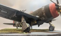
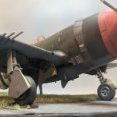
Cross posting this from my build thread in hopes seeking a wider audience. The cowlings are going to be an issue. The cowlings on all the subject a/c that I'm hoping to build all have the exhaust ports in the cowl itself and all cowl flaps are flat. The kit has the exhaust stacks channeled out the lower rear with the cowl flaps shaped to accommodate; the sides of the cowls are flat with no exhaust ports. Near as I can tell, every A-20G (which my subject aircraft all are) ran the same Wright R-2600-23 1600hp engine. So, what would account for the change in cowl configuration? The cowl in the subject photos. This is an A-20G-45-DO. None of the historical photos in Pacific Profiles that feature a cowl show this arrangement. Cowls and flaps represented by the kit. This is from the airworthy A-20 out of Texas. Wikipedia states its USAAF s/n is 43-21709 and Pacific wrecks claims that it is an A-20J-15-DO
-
Wait a minute, gents. Stop the presses. The cowlings are going to be an issue. The cowlings on all the a/c above all have the exhaust ports in the cowl itself and all cowl flaps are flat. The kit has the exhaust stacks channeled out the lower rear with the cowl flaps shaped to accommodate; the sides of the cowls are flat with no exhaust ports. Near as I can tell, every A-20G (which my subject aircraft all are) ran the same Wright R-2600-23 1600hp engine. So, what would account for the change in cowl configuration? The cowl in the subject photos. This is an A-20G-45-DO. None of the historical photos in Pacific Profiles that feature a cowl show this arrangement. Cowls and flaps represented by the kit. This is from the airworthy A-20 out of Texas. Wikipedia states its USAAF s/n is 43-21709 and Pacific wrecks claims that it is an A-20J-15-DO
-
Well hmm. After ~3 weeks of waiting, my Pacific Profiles book showed up at last. First world problems, I know. It's a wealth of information and has a ton of really interesting profiles, but I was hoping for a period photo that would really spark my interest and I didn't really find one. Right now, these are the front running contenders for kit. All are from the 417th BG. 43-21951 43-21426 nicknamed "Gladstone Flash" 43-22251 Sally [somethingsomething] - I'm having a tough time locating the name, so if anyone has information, I'm all ears. Same a/c in flight. The kicker for any of these is the tires, unfortunately. As I understand it, HKM used a current museum or flying example as their primary reference, so the treads on the mains and nose are not correct for any WWII variant. As you can see, the treads feature prominently in any (gear down) wartime photo. So, I'm in a bit of a quandary. Eduard has announced the release of a replacement wheel set with cross hatches, but there's no ETA on when those will be available. So... what to do... what to do. I could: Build everything as is and accept the tire issue. Pro: I get to complete the build and project without delay. Con: The incorrect tires will haunt my dreams. Build everything as is, leave the wheels dry fit until the Eduard set becomes available, then swap out at that point. Pro: Correct treads of course. Con: My gnat-like attention span may cause me to never actually follow through with the swap. Also, no idea when the Eduard set will be out. Get as far as I can, stop the build/project until the Eduard set becomes available. Pro: Correct treads of course. Con: waaaaaaaaaaaaaaaaaaaaaaaaaaaaaaaaaaaaaaaaaaaaaaaaaaiting
-
Bummer. Sorry about the frustration. Most of mine has been my own doing too, so I sympathize with you. You're absolutely right about the interior tolerances - they are very very tight. I found that with the large locator pins for both the cockpit and the bomb bay assembly, I didn't need to use glue to secure them. I stuck them to the pins, then closed the fuse around them and glued the halves together. I did use a little liquid super glue to get the weights to stay in place though, so I was able to avoid the problem you've experienced. Keep persevering! It's a great kit and, once the fuse is together, it's really smooth sailing from there on.
-
1/32 Douglas TBD-1 Devastator by Trumpeter - TBD-1A in October 2023!
ChuckD replied to Kagemusha's topic in LSP Discussion
It's here! Now, back to the A-20.- 376 replies
-
- 12
-
-
Thank you, all. I am flattered and humbled by your compliments. You are all very kind and I'm glad to give a little back to this fine community. <3 I moved on to the engines this evening and they were pretty straight forward. The rocker covers are molded separately and there are three separate varieties. The instructions are really pretty clear, so if you go slowly and take your time, it's easy to do. You can see that they are keyed slightly differently, so it's hard to screw them up too badly. What they look like assembled. At this point the covers are only attached to the pushrod tubes. I'm hoping that being able to separate the tube & rocker cover assembly from the cylinders themselves will help ease painting. It's an experiment, so we'll see how it goes. Trip report to follow. In general, the engines went together really smoothly. All the pieces - cylinder banks, nose cone, pushrod tubes, intake tubes - are keyed at the center shaft and, though the odds of screwing it up are low, they're never zero. I managed to cock one of the pushrod tube pieces up a bit, but no irreparable harm was done. Pay attention to the different size keys and ensure you have the different assemblies lined up correctly. The fiddliest part of the engines is the intake tube for the forward cylinder bank. Each tube connects at the two highlighted points. Given the angle of the tube, the itty bitty connection points, and the confined spaces, getting them to fit right and not fall out is a challenge. I don't necessarily put this on HKM; it's really about the best that can be done in such a situation. Radials are just big, complex, and geometrically weird devices that defy common sense, logic, and at times physics. So, HKM did the best they could and, once together, it looks great. Best trick I found was to put a bit of liquid glue at the base of the ring, tack on the intake tube, let it set for a second or two... Then use the tip of tweezers to push the other end into the small hole on the baffle piece. It helps to try to anchor the base with your thumb as you try to maneuver the baffle end. And, again in the end, they look pretty great. I'm glad HKM didn't dink with carbs, mags, accessory cases and other things like that on the back of the motor. That would've just upped the parts count and complexity to no real tangible benefit. After the engine, the cowl flaps are glued to a ring, the engine is inserted into the cowl, and the cowl flap ring is added to the rear. As you can see, the engine is quite on display, so I'll be adding ignition wires before everything gets all buttoned up. I'm not going to bother with the exhaust stacks until after I get them painted as they need to be added after you attach the cowl flap ring to the cowl itself. Both engines ready to go. The engines are not handed, but the cowl and flap rings are, so keep them separate and tracked. I did do a quick test fit of the dry cowl, ring, and engine to the nacelle and the fit looks very promising. I couldn't take a pic because I needed three hands just to hold everything together while I was trying to test fit. I would've needed a fourth to take the picture. And with that, outside of a few ancillary bits and bobs like propellers (I splurged on a UMM propmaster jig that should be here in a couple days), radio antennae, and such, the build is essentially done. I'll probably have a couple more build-ish updates as I do the sanding, scribing, and riveting dance and get more bits stuck to the wings and fuselage. However, all that is more or less finish work in prep for painting, and less the straight up, new build. To be clear though, I'll carry this thread through to the final finished product. I hope this won't come back to bite me in the butt, but I'm very impressed with the build. The engineering is excellent, the parts count to detail ratio is spot on, the molding is crisp and clean, and in general it's just fun to build. I'm not associated with HKM at all, so I have nothing to gain, but if you're on the fence about this one, it's a wonderful and enjoyable kit. Go out, get it, and enjoy having a big twin on your display shelf. Anyhoo, more to come. My Pacific Profiles book was apparently delivered to the local post office today, so I'm hoping it arrives tomorrow so I can start to settle on a paint scheme. More to follow!
- 163 replies
-
- 25
-
-
She's got leeeeegs! The right side was a 100% mirror of the left and led to no surprises. .... and she's trying to fly. I suspect once the engines and such are in place, it'll probably fall back on its nosewheel, but I was surprised to see the nose lift when I put the tail surfaces in place. I still might throw a sinker or two somewhere in the nose just to be safe. Anyway, on to the power eggs.
- 163 replies
-
- 26
-
-
I've been a busy boy today. First let's bang away at the nose. If it weren't for this build thread, I probably would've left a lot of this stuff out. However, I want to share my follies with you so that you can learn from my inevitable mistakes. Anyway, the tl;dr of this is, the nose fits great and the internals don't affect the fit to the fuselage - that all too critical join is very very nice even with all the internals in place. Blah blah. Less talk; more pics. First little issue - the instructions illustrate this little tab (K13) that sticks into the open hatch panel upside down. If installed per instructions, it interferes with the two ammo cans that straddle it. Flip it over as shown in the photo below. With that corrected, the right nose section goes together nicely. The steps are repeated on the left side. The only difference here is that the two notches in the side piece that ride over the ribs on the fuselage floor need to be widened. That small flare out on the ribs interferes with the side piece and prevents the latter from sitting flush with the curve of the fuse floor. I like that the ammo cans are split along the width of the can, not the long axis. I believe HKM adopted this non traditional method so that the modeler would not have to fix a seam line that would be visible when the side hatch is left open. More pictures below show what I mean better than I can explain it in words. Here I replaced the .50 barrels with the QB set. The kit parts were just as disappointing as the other .50 barrels. I glued the two bulkheads into the left fuse half to provide stability as I was trying to mount the .50s and it worked well. I was able to dry fit the nose (after drilling out the holes to accommodate the QB barrels) to help establish the proper alignment of the gun barrels. The lower .50s were mounted in much the same way. A shot of what's going on in the nose. There is tremendous room for detailing here and a fair number of the hatches can be left open if you so desire. I don't, ergo I will not be painting or leaving hatches open. The nose halves and nosecone are glued together. The fit was wonderful and HKM deserves the highest praise here. Once the sprue gates are cleaned up, all major parts fit together wonderfully and will require only the smallest amount of smoothing to get rid of any imperfections from the cementing process. Here you can see the seams in the ammo cans that I was mentioning earlier. Even if you opt to leave every hatch open, these seams will not be seen. Aaaand here's where I can level a complaint. The fit of the six panels on the nose is not super great. Relative to wonderful engineering that led to the flawless fit of all that junk in the nose, these panels were a let down. Ignoring the fact that some of the liquid cement wicked under my finger and marred the surface (I'll fix that later), no amount of finagling could get any of these panels to fit without some sort of filler being required. I think HKM intended for the modeler to leave them all open, leaving some of us to deal with a sub-par fit. Okay, okay, they're not awful and I have definitely seen worse, but I was a bit let down by them after the rest of the nose fit so well. A little filler and a some light sanding ought to be enough to hide them under a coat of OD green. If I were doing NMF, that'd be a different story. But I digress. There's a forward bulkhead that goes into the fuselage that I wasn't aware of while painting. I wish I had been because, as you can see, it's quite obvious as it forms the forward wall of the nose wheel well. It's dry fit here and required just a little bit of sanding to fit the assembled fuselage, so it'll go to the paint booth in the next day or two. Here's the nose taped together. Again, the fit is wonderful. I haven't test fit the cheek panels yet, nor added the PE (presumably) armor strips that go next to them, so we'll see how those go. But, again, even with all the crap crammed into the nose, it fits the fuselage nearly flawlessly. The aforementioned PE armor plating. On to the left main. Contrary to the chintziness of the nose gear (thank you Douglas Aircraft Corporation), the main gear is a sturdy mess of triangles, braces, and stiffeners, oak board, concrete, titanium, and a kitchen sink. Assembly is straight forward except for the little doodad that looks like it's got a pulley on it (see arrow). The instructions are not clear as to where it goes and there's a small slot on the bottom of the main swing axle into which it fits. I originally fit it into a slot on the other side of the axle and it was just not right, thus the messed up glue bit. Live & learn. I also left the door actuator rod off and will install it once I have a gear door to attach it to. It attaches to the little Y yoke towards the bottom left. After the landing gear comes the nacelle. It was very painless to assemble with the exception of this one little piece. Again, the instructions could be better here as the angle they show for the little brass divider on the intake doesn't really help you understand the placement. It's a lot harder than I thought it would be to find a photograph of the inner side of the engine nacelle, but I finally located one on some russian site somewhere. I'll probably be ransomewared by morning, but whatevs. It's just my modeling PC. Anyway, the brass part should more or less divide the intake and should not stand out forward of the lip of the intake itself. Oh, I also assembled the tires too. If I do this kit again (and I may, it's quite fun), I will deffo spring for the Eduard wheel set with the crosshatch treads. The kit set is workable but underwhelming. I then moved onto the left wing (the engines will come later). The assembly here was without issue and the fit was magnificent. The leading edge seams will clean up with minimal effort and the same can be said for the 3 control surfaces. The carb intake is glued on. It doesn't have any keying to line it up, but there's a panel under it that matches its outline, so it's hard to mess up. It fit perfectly. With a Tamiya cement bottle doing a stand in for the right wing, I locked the left wing in and set her up. She's definitely starting to look the part! I was a little hesitant to test fit the wing. I did that with the B-25 and it never came out again. Happily, the left wing on the A-20 has been more compliant to my efforts and can easily slip on and off while still locking in tightly when in the proper place. Very little, if any, gap on the upper wing root. Lower wing root is very nice too. I was able to finagle it a little bit after this picture to get it to fit better towards the leading edge. So, I'm optimistic that the wings will be a very easy install. A shot showing the full length of the wing. The nacelles fit nicely as well. There may be a small gap on the upper surface where the nacelle meets the wing behind the carb scoop. I can't tell yet if that's just an artifact of the taping job or whether or not it'll require filler. Either way, it's not too bad and shouldn't be a problem. I wanted a visual reference as to the size of the A-20G vs the B-25J. As you can see the latter is quite a bit larger on the shelf. Thanks for following along. I suspect I should be able to get the right wing and gear done tomorrow, then its off to paint some more, then to tackle the engines. I'm hoping my Pacific Profiles book comes soon - my wife ordered it for me for father's day and it's still not here. It's now due in "by Thursday" but we'll see. Failing that, I've found a few neat Pacific birds that I could probably emulate. I enjoy trying to recreate historical photos, so I want to find an A-20 on the ground, but most of them were photographed in the air. Anyway, I'll settle on a paint scheme before too long. I promise.
- 163 replies
-
- 20
-
-
It drops in, so you can remove it at your leisure. I think it's snug enough that it's not just going to fall out, but it can be removed without too much hassle. I had a few minutes before work this morning, so I poked around at a few things. The tail pieces went together pretty well. They are large and sturdy with solid connection points. The connection points allow for complete freedom in positioning the control surfaces. I didn't photograph it (would've needed 3 hands), but dry fitting the stabs to the tail looks like there will be some tweaking used to get things to fit without gaps. I'm going to leave the tail off until I get wings and landing gear under the model because I don't want the tail surfaces to be load bearing while the unfinished kit is sitting on its side. To emphasize my point above, when the kit is sitting on its side, the wing roots force the fuse to roll towards its belly, so the nose gear takes up a side load. I might move on to the wings after this (as opposed to the engines as per instructions) just to get some leveling factor and to get the load off the nose gear. I had just a few minutes to dink around with the fit of the nose. Having done the B-25 and B-17 from HKM, this was a concern for me as neither of those kits had great fitting noses. I'm very impressed with the tentative fit here on the A-20 kit with the caveat that none of the internals are in place yet. Here you can see the fit with nothing more than the weight of the two nose fuse halves holding it in place. This tiny gap here will likely shore up very nicely with cement.
- 163 replies
-
- 22
-
-
Eeeh, I don't know, I'll have to look. Could be the latter. Short term memory and all.
-
Hi, guys. It's been a little bit, but I've been far from idle. I just tend not to get too bogged down with photos of the various phases of interior painting... priming, base coating, detail, chipping, decals, filters, washes, dirt, etc. So, here we go. The Quickboost B-17 .50 barrel set came in. As you can see, the difference between the kit barrel and the QB barrel are night and day. Borrowing from @leoasman, I thinned the back of the IP, drilled out the dial faces, put the decals on a cardstock backing piece and glued that to the back of the IP. Worked like a champ and I'm glad they posted their methods. Anyway, for spraying the flat coat, I masked the IP with silly putty. The decals are a mix of kit decals and some from an Aeroscale generic cockpit placard set that I had. The yellow framing around the six pack is just super thin tamiya tape strips. The final product after pulling the putty. A few shots of the interior at the end of the finish work. The MRP zinc chromate is a bit bright yellow, so I toned it down with oil washes, enamels, and speckling. In photos the speckling looks overdone, but in 1:1 scale, they're much more subtle and go a long way towards breaking up walls of color. Again, Aeroscale decals. Chipping was done with the sponge technique using Vallejo Model Air silver. The cockpit roughed in. The nose wheel well with lots of dirt and mud splashes. The bomb bay deconstructed (and sans the actual bomb racks). More Aeroscale decals. Before this gets buttoned up, I'll add a gunsight reflector from clear film. Ye olde bombe racks. I went with natural finish for a little visual interest. The upper deck above the bomb bay. Nothing aft of the three small radios is remotely visible, so I didn't do much painting here. If you wanted to add a bunch of details, it's a pretty awesome blank canvas. The luggage rack. Nose gear and rear ammo can. The QB barrel installed (some more detail painting was done later as shown). The MGs are the weakest parts of the kit. If you're really concerned about the soft detail here, the Gaspatch M2 is going to be the way to go. Ye olde bombes for said racks. Assembling the nose well. The bomb bay is assembled. Very little of the sides walls can be seen. Dry fitting the turret while the glue on the bulkheads dries. The cockpit assembled. One last shot before it's closed up and lost forever. A quick shot to give an idea of how much is going to be visible once the canopy is put in place. Short answer is: Not much. The turret. Bomb bay after assembly. Not much can be seen here. Fortunately, the part that can be seen is the QB barrel. A milestone! The fuse went together pretty well. The little section between the nose and bomb bay is still the gap that requires the most physical strength to shore up. A lot of liquid superglue was the remedy for getting it to stick together. The plate that forms the base of the vertical stab fits reasonably well, though there's a gap on the left root. Nothing too bad though. The shot below is dry fit and the cemented gap is much smaller. Next it's building the nose and tail feathers, then on to the engines. More to come!
- 163 replies
-
- 34
-
-
1/32 Douglas TBD-1 Devastator by Trumpeter - TBD-1A in October 2023!
ChuckD replied to Kagemusha's topic in LSP Discussion
It shipped! Should be here within a few days. -
Agreed with Uncarina. This hobby is about the journey, not the destination. Enjoy the build at whatever speed works for you and we will follow along just the same. Your work is looking great. It's funny... You mention losing your mojo every time you open the box in this kit. I feel the same way. Its currently sitting on my shelf of doom with the fuse halves together and the cockpit done. But every time I go back to it, I end up putting it away again. Not sure what it is about this kit.
-
1/32 Douglas TBD-1 Devastator by Trumpeter - TBD-1A in October 2023!
ChuckD replied to Kagemusha's topic in LSP Discussion
I got an order update from Squadron on Friday. My order status was changed to"shipping June 30th." -
Kind of a moot point, unfortunately. They're out of stock too. Grab the last one on ebay from Hong Kong if you want it.
-
Is it even in stock anywhere now? All the usual shops are sold out. I wonder if aftermarket companies like the decal and seatbelt shops get angry when they put effort into to researching and creating products only to have the kit manufacturer pull the plug.