

Greg Springer
-
Posts
81 -
Joined
-
Last visited
Content Type
Profiles
Forums
Events
Everything posted by Greg Springer
-
I'm converting a PCM Mk IXc to a XIVe s/n RM619. I am using the Aires Mk V cockpit with suitable modifications. I would like to know if the compressed air and oxygen bottles should remain behind the seat or would they have been relocated to the wing bays for the removed .303 Browning guns at this point in production? Cheers! Greg
-
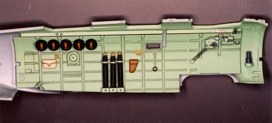
Last but not least is the port side of the cockpits. From the left upper are the drums for the Lewis gun. Below at the rear is the outlet tube for the trailing radio wire antenna. The round object below the ammo drums is the reel on which the trailing antenna is stored when it is retracted. The tan pouch probably contains tools for Lewis gun maintenance. To the right are the oxygen bottles for the crew. These were taken from a Hawkeye resin detail set for the Zero. The rack for these can be seen in the upper photo on page 199 of Japanese Aircraft Interiors 1940-1945. Beside the tanks is a flare pistol holster. The object beneath the window is the top mount for the horizontal bombing sight when it is in use. The brace is hinged. It is rotated into the horizontal and the black loop is clamped around the eye piece of the sight. I don't know what the gray cylinder on the far right is but it appears in the photos in the Interiors book so I included it. Loic, I hope you find these useful. Good luck on your project! Salut! Greg
-
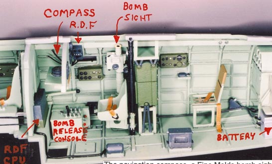
Here's a shot of the observer's instrument panel. In the center is the opening for the navigation compass. These compasses have a prismatic reflector on them so they can be read horizontally. On either side are secondary flight instrument clusters. Upper right is the round housing of the RDF loop antenna rotation control. To its right is the RDF control box. At the bottom of the panel the navigation chart table is mounted in the retracted position.

-
Now the starboard side of the mid and rear cockpits with the seating installed. The observers seat was mounted on a vertical steel tube on the center line. It could be raised or lowered and could be offset to the port side to use the observation window. The offset gearing was such that the observer seat remained perpendicular to the centerline. I installed the Fine Molds bomb sight on the starboard side as I felt it was more suited to that position. I will allow that it could have been on the port side as well. In the observer's cockpit labeled 'RDF' is the RDF control box. To the right of the black tube is the radio rack. The IJN shock-mounted their radio gear with bungee cords looped over thimble-shaped pegs on the radio sides. The green boxes on the cockpit walls are lighting controls for each cockpit. Below the rearmost is the radio operator's telegraph key. Continuous Wave telegraphy was much more powerful and reliable than voice transmission. Next is the radio operator's folding seat with cloth straps for the seating area. It could be folded out of the way when the operator manned the rear Lewis gun. That's all for tonight. I'm going to drink a Duvel. Cheers! Greg
-
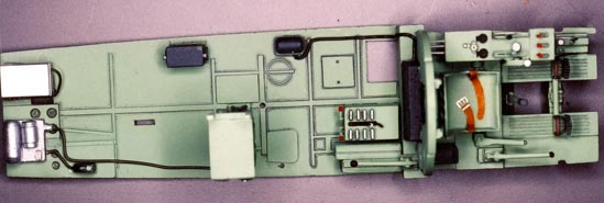
Now for a view of the cockpit decking from above. The black oblong behind the front bulkhead is the main processing unit of the Type 1 Mk 3 radio direction finder, a copy of the Fairchild Radio Compass RC 4. The wiring from it is connected to the black dynamotor power unit on the left deck of the observer's cockpit. To the right (below) the centerline is a rectangular box with eight handles in two rows on top. This is the bomb release console. Different bomb loads can be released singularly or salvoed by selecting the various release handles. Beside the console are two narrow obong boxes that held Very-type signal flares and possibly navigation drift indicator floats. Directly aft (left) is the top shelf of the radio rack. Hasegawa molded the rack as a single cabinet which is incorrect. However the face of the Type 96 Mk 3 radio set is absolutely accurate. Another heavy black cable runs from the radio to it's dynamotor module in aluminum at the rear of the rear cockpit. The large dynamotor powers the transmitter; the small one the receiver. This is the same radio as used in the Betty. Finally, to the left (above) the dynamotor module is the box containing the aircraft's battery. More to come...
-
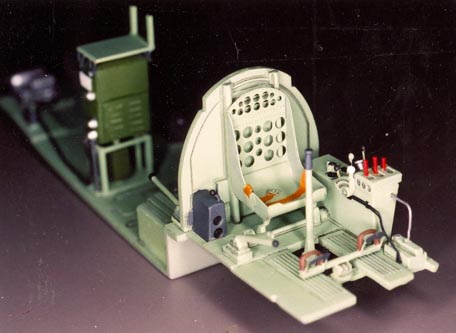
Next, the front cockpit seating area. Note that the radio stack has been moved to the starboard side of the cockpit. Hasegawa incorrectly placed it on the centerline of the cockpit deck. However the photo of the flaps hydraulic piston actuator service access hatch in the upper right corner of page 19 of the original Maru Mechanic clearly shows the left front support leg of the radio rack sitting on the center line. Also moving the rack to the right places it in front of the radio operator's seat. The etched back of the seat was wrapped around the seat portion of the kit part. Note the lack of a deck between the rudder pedal foot boards. The emergency hydraulic hand pump is repeated in front of and behind the dark gray gear box of the main gear retraction mechanism so either the pilot or the observer could operate it. In the Mikesh photos of the Saipan Kate there is a tank and piping mounted behind the pilot's seat. This may be a tank for high octane gasoline used for take-offs with full war load like the ones found on the Val. The cutaway drawings in the MM don't show it as they are for the B5N1. Greg
-
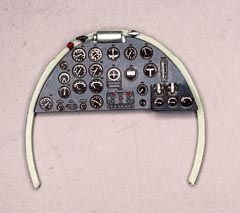
Well I think I'll pitch in with some pics of the cockpits of a Hasegawa 1/48 Kate I built back in 2003. Most of the additions and corrections I made were a result of photos in Mr. Mikesh's Japanese Aircraft Interiors 1940-1945 and the original Maru Mechanic #18. First, the pilot's instrument panel. It's from the Eduard PE set with some T-handles added per the Mikesh photos. I hope you find these useful. Cheers! Greg
-
Spitfire Mk VII cabin compressor intake?
Greg Springer replied to Greg Springer's topic in Aviation Discussion & Research
Hello Dave and Hans, Thank you for your replies! I also had an e-mail from Vasko who states that there was a wire mesh in the separate frame in front of the intake pipe. Hans, I would be very interested in seeing your pictures. e-mail is gspring@ix.netcom.com. Thanks again. Cheers! Greg -
Does any one have information on the structure of this intake below the starboard exhaust stubs? The kit parts I have depict it as a cylindrical tube with a flared front end like a trumpet and it tapers to a point at the aft end. Some drawings suggest that the tube is cylindrical with a separate structure in front of the intake, perhaps with a wire mesh screen to stop foreign objects from entering (?) Any information will be gratefully appreciated. Cheers! Greg
-
The Munsell color system, now owned by Gretag-MacBeth, divides colors up as follows. First is the wheel of hues (named colors). Some hues, like red and yellow have stronger chroma (intensity) than others. This is shown by the length of the hue segment on the wheel. High chroma colors extend farther from the axis that low chroma colors. The wheel is around a value cylinder. The value cylinder is pure white at one end (value 10) and pure black at the other (value 0) with shades of gray in between. If you choose a color and move the wheel towards the black end of the value cylinder it becomes more gray and dull. Scale Effect only works with colors that are of low value and chroma. I. e. camouflage colors. Colors of high chroma and value do not fade with distance. They are commonly used for markings although the RAF in WWII dulled their roundel red to a low value red brick color for lower visibility. But they did not do so with their ID yellow leading edge stripes. You can experiment with this if you have a MicroSoft OS with Paint drawing software. Open the Edit Colors pallette and go to Advanced. You will see the hue box with crosshairs to locate a color and the value bar on the right. Chose a color and move the value up and down the scale. BTW the treatise in the Hitchcock Luftwaffe Colors book was written by Pat Donahue. Cheers! Greg
-
Ok I picked up my Pacific Coast Mk. IXe today. Decals for FN-Z PL187 of 331 Norwegian Sqdn. Sept. 1945, RAF roundels + Norwegian colors on the early-type rudder. WR-RR PT672 of Lt. Col. Robert Rogers SAAF, orange replaces red areas in roundels, tall rudder HL-M-4 SL628 Wng. Cmdr. J Hlado, Czech AF 1945, tall rudder 4D-W NH609 74 Sqdn. RAF Schijndel, Netherlands, March 1945, tall rudder "57" TE554 Ezer (Why not Heinz?) Weizman, Israeli AF late 1970. Allover gloss black with red nose, rudder, radiators and lightning bolts on sides of fuselage. Tall rudder. SM622 unknown unit Red Air Force. Tall rudder. All subjects have standard wing tips. Nit pick time! The instructions for mounting the wing armament remain as for the IXc. We are told to discard the short cannon barrel shrouds and mount the long ones inboard with the rounded plugs outboard. In fact, as the box art and the markings profiles show, the short shrouds are used in the outboard position and the plugs can be drilled out and installed backwards in the inboard position for the .50's. See my last post for correcting the ejection chutes to the 'e' armament configuration. Cheers! Greg
-
PCM Mk IXe arrived at King's hobby this week. The underside of the wing retains the 'C' armament arrangement. I drew up these sketches over the weekend so that modelers can easily correct their wings. Fill the ejector ports in the outer two gun positions but don't fill in the panel lines as the gun and ammo bays were used as new locations for the compressed air and oxygen bottles formerly behind the pilot's seat. Cheers! Greg

-
How about the revised shell casing and links ejection chutes for the E armament mix? I doubt there is an entire new wing underside being molded. I already converted my wing as I intend to make my IXc into a XIVe. There is an excellent photo on page 131 of Wings and Wheels "Spirfire LF IX in Detail" showing the arrangement beneath the port wing. I measured the details and converted to 1/32nd. Some K & S 1/8" o.d. aluminum tube and Quick Boost P-38 gun barrels make for an easy reproduction of the .50 Brownings. Cheers! Greg
-
Spitfire Mk IX main gear leg dimensions?
Greg Springer replied to Greg Springer's topic in Aviation Discussion & Research
Thank you Gentlemen! I dug out my references this morning and realized the early Spitfires up through the Mk IX had no external links. This is most obviously shown by the drawings of the Mk V gear leg in the old RAF Museum publication I have been working with. Since I am converting my Mk IX into an early Mk XIV I shall be using the photo-etched links provided in the PCM kit. They are very nicely etched but a bit thin and very fragile. I'll be sandwiching some .015 styrene sheet in between the metal halves for a better scale appearance. Again, thanks! Greg -
Spitfire Mk IX main gear leg dimensions?
Greg Springer replied to Greg Springer's topic in Aviation Discussion & Research
Wow! Thank you very much Rato! Edgar. No links? Was the oleo piston prevented from shimmying by some internal mechanism? How about the early Mk XIV with the E armament? Links or no links in June of '44? Thanks! Greg -
Spitfire Mk IX main gear leg dimensions?
Greg Springer replied to Greg Springer's topic in Aviation Discussion & Research
Thanks very much Ray! I needed the info to check my calculations from a drawing in the RAF Museum's reproduction of the Spitfire V maintenance manual. I had it figured at 1/17 scale and that turned out to be very close. I was only 4mm off in the full sized dimension from the center of the pintle to the extension end. I also had a look at an online dictionary. A pintle is a solid pin as is a trunnion but the pintle needs a gudgeon to rotate arround it and I should have used that term. If you want a hoot, look up 'pintle' and see its meanings in Old English and in Scottish vernacular. (Hint: one meaning is 'peg'.) No Jack, I'm not building a full-scale Spit. I'm making gear legs for my new Pacific Coast Models Spitfire IX kit from aluminim tube since the kit parts don't live up to my standards for strength or appearance. Thanks again! Greg -
Hi Everyone, Can anyone provide me with these dimensions in full scale? The length of the gear leg from the lower apex of the trunion to the entry point for the olio ram. How about the diameter of this section at its smallest diameter and widest diameter? Thanks for any help you can provide! Cheers! Greg
-
Hello Stephen, The A6M2 model 21 has the long span wing with folding tips. It was powered by the Sakae model 12 engine with a short gear case and gun troughs atop the cowling. This is also true of the Rufe but without folding wingtips, rollover pylon and brake pedals on the rudder bar. The Tomy/Swallow/Doyusha kit is quite accurate in outline but the cockpit needs reworking and improving. It can be made into a nice Rufe with a conversion set. The subsequent models were powered by the Sakae 21 with a longer gear case and down-draft carburettor that required a new, longer cowling and shortening of the forward fuselage. The model 32 simply removed the folding tips. The model 22 retained the long wing but added extra fuel tanks in the outer sections. The model 52 went to a shorter, heavier-built wing with the same span as the type 32 but with ailerons extended into the rounded tips. HTH! Cheers! Greg
-
Hi Russ, Here's a link to MM's review of the Warbird's Mk XIVc conversion with four spoke wheels and fishtail exhaust. Casting looks very good. I'm placing an order with Dan at Warbirds Productions USA! Keep up the good work! http://modelingmadness.com/scotts/conversions/wbdsa3214c.htm Cheers! Greg
-
This is such a great build! I am collecting stuff to do one of my own but I am going to base it on the new Pacific Coast Mk IX. Can anyone tell me if the Warbirds resin nose is reasonably correct? After seeing all of the work needed on the rocker cover fairings of the Mk 22/24 I am strongly considering purchasing one. However I already have the 22/24 and the Warbirds conversion is the same price as the PCM kit. I intend to build it as AP-D RM619, the box art subject for the first Academy Mk XIV release as I have a tenuous connection to that aircraft. It was later transferred to 350 (Belgian) sqdn and was shot down near Aachen on 14 January, 1945. The pilot, H. J. Smets, survived the war. He is/was the cousin of my friend Michel Tassin. Cheers! Greg
-
Nice work! Now I have a question. Is the lower cockpit correctly molded with the rounded fuselage cross section? The Aires cockpits for the Hasegawa Mk V and the 1/48 Mk IX have that feature. AFAIK no major injection manufacturer has ever gotten it right. Cheers! Greg
-
Don't forget to remove the brake pedals from the rudder bar and the landing gear selector on the right rear side of the cockpit as well as the landing gear uplock release t-handles from the small box on the right forward deck. You can probably remove the floatation chamber control valve (the large pipe and wing nut on the left upper side of the cockpit). There is indeed a pressurized fuel tank in the main float. You will be fairing over the tail hook well to install the keel. Cheers! Greg
-
Hello Bruce, In my online search I found a description of the carb. It was a Stromberg single-throat downdraft "pressure type". Would that indicate it was downstream from the auxiliary supercharger? BTW how can you be in La Porte and Houston at the same time? Something you learned from the Guide? 8^)> Cheers! Greg
-
Howdy Gents, According to drawings in "Illustrated Zero Fighter" by Shigeru Nohara, the seat is 550mm high, 350 mm front-to-back, 420 mm wide at the seat pan, and 340 wide at the top of the seat back. So in 1/32nd the seat would be 17.2 mm high X 10.9 mm ftb, 13.1 wide at seat, and 10.6 mm wide at the top. Allowance may have been made for the thickness of the fuselage sides. Cheers! Greg
-
Hi guys, I got this reply from Pat Donahue over on HyperScale: "Greg, you are pretty much right. Induction air enters the aux. blower section through 2 oblong ports at the top of the aux. blower section. The air was compressed and then it went through the intercoolers and then to the carb. The fuel was added and then the mixture went to the main stage blower which distributed the mixture to the cylinders. I would ASSUME that there was some type of shuttle valve in the cowl carb. intake that would direct air either directly to the carb. if one was operating in main stage blower or diverted the induction air to the aux. stage blower if that was being used. I'll see if I can find an induction diagram. Yes, both blowers were mechanically driven. It was a 2-speed 2-stage supercharging system, the world's first in production. When the aux. stage blower was not in use it was left in neutral as in takeoff or landing and at low altitude so as not to over-boost the engine. ie the engine was running only on the main stage blower, no extra supercharging or innercooling from the aux. section blower." This seems to be like the system on the R-2800 as well. Greg