

LSP_Kevin
-
Posts
48,482 -
Joined
-
Last visited
-
Days Won
280
Content Type
Profiles
Forums
Events
Posts posted by LSP_Kevin
-
-
I'm guessing RLM 23 Jim, but I don't really know.
Kev
-
Just looking to replace the kit seat on my Matchbox Spitfire 22/24 build, and am wondering if all Spitfire seats were roughly the same. There are several AM replacement Spitfire seats on the market, but they're all described as suitable for earlier versions. If I can use or adapt one of these seats, I'd much rather do that than scratch-build one!
Kev
-
Photos!
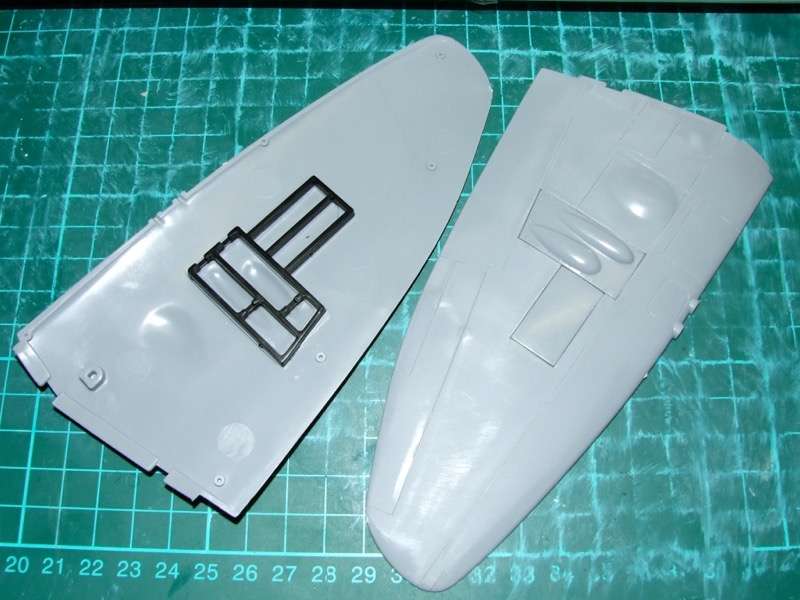
I fitted the gun bay covers, and added the internal framework on the assumption that it would add some internal strength to the otherwise quite flimsy parts. They do interfere slightly with the fit to the bottom wing, but nothing serious.
The fully assembled engine:
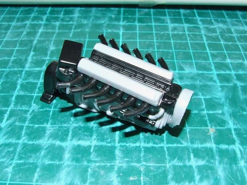
I'm not planning to expose it, so it'll just be there for its structural requirements.
Here's a couple of photos that attempt to illustrate the size difference between the kit and vac sliding canopies:
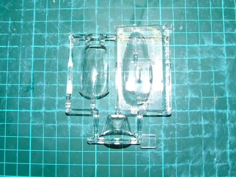
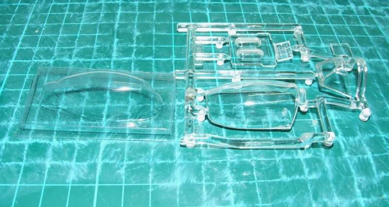
Quite hard to capture the outlines with clear parts! They appear to be similar in height, but the vac part is far narrower in cross-section, and would not mate up the windscreen at all (it would probably slide inside it in fact). Is there any obvious reason for such a discrepancy? Is the kit part too wide by that much?
Kev -
Thanks for posting the link to that list Mark. Looks like there a quite a few there that haven't made it into the Kit Database yet, so this will give me a reference list to work from.
Kev
-
I'm still wayting for part 3 of Ray's Emil kit comparison...
I believe that might be coming soon...
Kev
-
Hey, don't sweat it Tim. I like the fact that these older topics are being revisited. I just want to ensure that folks understand the content isn't fresh, and the OP may not necessarily see the new posts.
Kev
-
OK, after 6 months and a couple of pages of chit-chat, I've finally started this thing! No photos at this stage, as I'm just assembling the engine, drilling out the exhaust stacks and generally getting a feel for what needs to be done. I was hoping for a reasonably speedy build, but it's clear to me now that this kit will require quite a bit of work, especially in the cockpit. Looks like I'll need to brush up on my references!
One thing that struck me though, is that the vac canopy from Grey Matter looks noticeably smaller than the kit's canopy. Is that to correct an over-sized kit part? My main concern about it is that, at first glance, there's no way you could pose it closed, as the vac sliding portion would virtually slide inside the kit windscreen.
James, I saw your build on ARC - very nicely done!
Kev
-
Any more updates on this one mate? I've just started work on mine, and was really hoping to follow your lead!
Kev
-
-
Wow, that looks pretty good! I saw photos of the scratch-built prototype somewhere recently, and it looked fabulous. May I ask how much you paid for it?
(LSP admin - if you want to use any info/pix here to add to the kit database, feel free to do so. I have no objection to photos being cropped or resized if needed. First photo shamelessly borrowed from the internet)
Thanks, will do! The kit is already in the database, as the guy behind LEM contacted me recently with updated information on his kits, so having some images to go with it will be very handy.
Kev
-
Thanks Michael. I did give the mould a series of light squeezes to try to force the resin along the mould, and I thought it had worked pretty well until I demoulded. I suspect the solution requires a re-engineered mould to better accommodate the pouring process. I'll give it one more go using this current mould, using Dan's talc method to see if it improves the flow, but if that fails it's back to the drawing board.
Kev
-
Well folks, Round 4 was interesting. I thought I had it nailed, as I could see resin coming up through both air vents by the time I finished pouring. But upon demoulding, I get this:
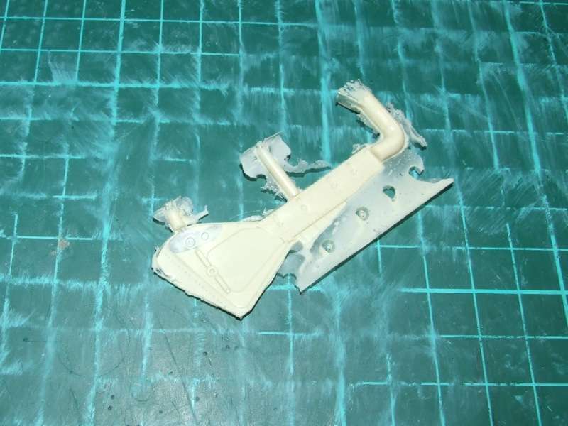
It looks like the resin has flowed around the air bubble, instead of pushing it out. There's an ultra-thin skin of resin on both sides. As you can see, plenty made it up the air vent itself, so I don't really understand how this has happened. I forgot to try Dan's talc tip, so I'll do that next time, as he's given me the lowdown on how to apply it to the mould.
I'd love to hear your collective thoughts on why I ended up with this trapped air pocket. I think I probably need to regroup, process what I've learned and start another new mould using that info. This one's way too leaky anyway!
Kev -
Did you try and use a dusting of talc? Might help the resin get into the tiny thin areas. Just make sure if you do that you blow off almost all of the talc. All it needs is the faintest of coatings( you almost can't see it.)
How thin is the resin you are pouring? It should be quite thin. Sometimes with the cold weather it can get a bit stiff and that won't help you at all.
I didn't try the talc, as wasn't sure exactly how to go about it (brush it on? pour and blow?), and I didn't want to introduce too many new variables at once. But I'll give it a go on the next round. The kitchen spray that I'm resorting to for the moment as a mould release (for the second pour of the RTV) tends to bead up on the rubber, leaving lumps and impressions that the resin - of course! - captures nicely. So there are a few flaws in the mould, but nothing I can't clean of the resin after the fact. I don't plan to make any new moulds until I can obtain some Vaseline.
As for the thickness of the resin, when first mixed it's pretty much like milk, but thickens rapidly while I'm pouring. Because my pour hole is too small, this takes longer than it should, so by the time I've finished pouring (and prodding, and poking, and squeezing), it's getting on more for runny honey. This obviously doesn't help!
Let's see how I go in Round 4...
Kev
-
Just keep in mind fellas that this topic is two-and-a-half years old!
Kev
-
Nice to see you back at this one Dave. It looks like you might be closing in on the painting stage!
Kev
-
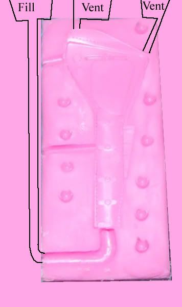
If I may, I'd also like to suggest making molds for a long, thin parts vertically. Again, this helps gravity force the resin through the mold:
HTH,
D
Yeah, thanks again mate. I was beginning to come to that conclusion myself, but your diagram really makes it clear how to go about it. I'm going to make do for this particular gear door, but since I need to make a starboard one too, I'll give your modified approach a shot. I guess I just had the misfortune of needing to start with something that's not so straightforward for a beginner. I certainly appreciate all the help and advice though! (And I probably should have spun off a new thread in the Tips forum, to be honest.)
Kev
-
Thanks D, good advice. It addresses a couple of related issues I'm having, both of which probably contributed to this round's result. Firstly, I have no real way of telling how far the resin has proceeded along the mould. For the first pour, I could see some resin coming up the far air vent, so it seemed all was well in that regard. This time however, I didn't see that, but I couldn't get any more resin to pour into the mould, I think partly due to the opening of the pour hole being too narrow. I'll try to cut a wider opening out of the RTV. Of course, if I had a trapped air bubble up the end that wasn't venting for some reason, that probably isn't going to help, so I may have to consider widening the far air vent too, or at least the junction between it and the part (which is exceedingly small, and may in fact not be very effective at all).
I'll have another go tonight and report back.
Kev
-
Very cool. The cockpit area looks terrific.
Grant.
Seconded. It's builds like this that put me off starting my Ju 88, as I don't see how I could achieve such awesome results!
Kev
-
BTW, I am in the middle of doing a 32nd Harrier T.12, so it is deja vu all over again---
Frank
We'd love to see it Frank!
Kev
-
Thanks for the ideas, tips and advice fellas - I really appreciate them! In an effort to push forward, and in the true spirit of learning by doing, I've had another go. I'd already put the mould box together and laid down the clay before reading Dan's advice about a bigger mould box. I used more and smaller key holes though, but they didn't work out so well (not sure why, but the RTV didn't fill them properly).
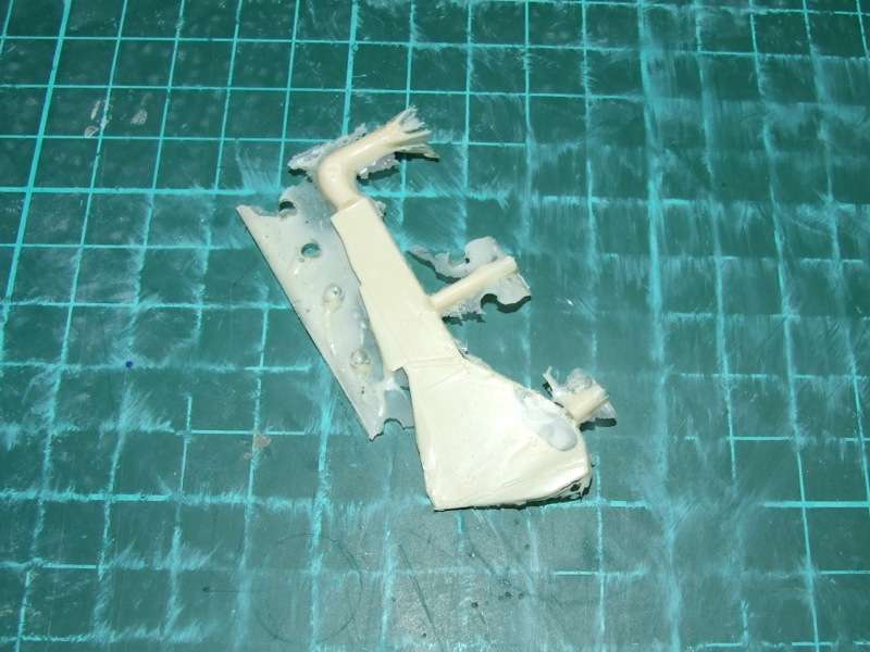
Anyway, the result represents one step forward accompanied by one step back: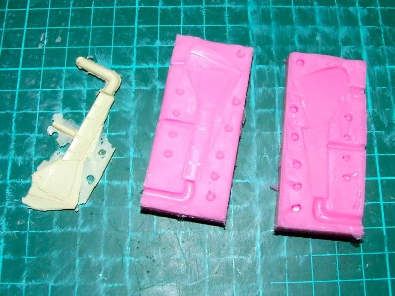
The mould has captured the part properly with no lifting or slippage, but as you can see from the photo, with the wide end of the mould now being, correctly, much thinner than the previous one, the resin failed to make it all the way down there during pouring. There's an air vent at that point, but it's not particularly large due to the thinness of the part in that area. At least I can reuse the mould without having to make another one - finally! Would I get away with pouring some resin from both ends?
Kev -
Wow, tough gig! Looks like a lot of fun though. I'm pretty sure Quickboost do a set of D-9 exhausts that you might be able to get away with.
Kev
-
Hmmm....I think you made one of the same mistakes I made when creating a RTV mold. Mold release agent is really for helping to remove parts from the mold. It does not work too good for the second half of the RTV material; in other words, for between RTV and RTV.
You're probably right Ray; but that begs the question: what does?
Kev
-
Given my new-found interest in resin casting mate, I'm definitely watching this one!
Kev
-
Wow, fantastic cockpit work mate!
Kev

Red colour for early Luftwaffe red tail flash?
in General Discussion
Posted
Well, that's two guesses for RLM 23! In terms of paint options, Gunze makes one (H414), as does Vallejo in their Model Air range (AV 71102). Not sure about other brands, but I'm sure there would be others.
Kev