
Crossofiron
-
Posts
82 -
Joined
-
Last visited
Content Type
Profiles
Forums
Events
Everything posted by Crossofiron
-
LOL, like a modelling bad smell..
-
Hello All, Although a small part of the build, thought I would share this as it's quite involved. Airframe 11. As shown previously, this is the kit part with two Airscale etch parts overlaid. Here are the Kit Parts; The Seat and Seat Frame are from Aircraft in Pixels and is there Mk.I Spitfire Seat 'Updated' to composite. No kidding; off the charts this particular set, never seen anything like it, it even works and I was able to set the height for Johnnie! The Top Armour Plate is Airscale The Seat Armour Plate is bespoke. An interesting point here; In my spitfire construction manual, the top armour plate references steel with a thickness and finish meaning is is machined which I have reproduced. The bottom plate reference ' stock' in other words rolled flat steel as it came from the foundry based on this, I gave the bottom plate a rough finish and allowed for oxidisation, particularly the back as the stock steel is not treated for paint and would come through the paint after time as it rusts. The wear points are 'oily steel' rather than aluminium to differentiate the materials in the cockpit I lightened the top around the headrest to allow for a certain amount of bleaching in the sun The Altitude Meter behind the armour plate is bespoke and is correct to the period; the Tamiya 1/32 Spit shows a post war unit Anyz Models do a rather nice 'deformed' headrest in all scales which looks great The Harnesses are HGW of course The Voltage Regulator is true of this Mk.IV, the kit part is Mk.V to Mk.VIII There are 3 cables to the Voltage Regulator and these are run in a black sheaving in the route as per the below, not around the airframe As the three cables come out of the sheave, the sheave is given a serial number for traceability The Aileron Cable Pivot assembly is bespoke etch The Flares are 3D Printed Between the flares, there is retrofit box compartment for a Field First Aid Kit Many thanks for looking Cheers Steve
- 55 replies
-
- 13
-

-

-
Sending you a PM mate
-
LOL, Once MSM have you, there's no going back! Seriously though, for the relatively easy installation it's next level modelling. The best bit for me is the sound; my video doesn't do it justice it's somewhat loud!
-
thanks John, honestly, it's not that bad, MSM provide great instructions. The challenge is working where the cables can run without seeing them. Especially when so much of my Spit is exposed. Also fun through
-
Thanks Mike! My better half agrees with you, says I'm bonkers!
-
Hi Matt, Thanks for the post. The circuit is low voltage so heat is not a problem. The LED's emit no heat either. Cheers Steve
-
Hello All! Work has been hellish so I haven't got as far as I'd liked but I so have some bits to show you. Control Column Here is the Airfix Version; The front is okay but there is no rod to the Elevator Lever (there is not one of them either) Here is the rather stunning Barracuda Studios version for the kit; You get three versions in the kit depending on the subject you are building and the detail is immense! The one shown is the e wing version and note the red gun camera button. https://barracudacals.com/ Instrument Panel Rear I have also completed the back of the instrument panel; Bespoke Etching and framework 3D Printed Instrument housings The Connectors are from Anyz Models Here she is cabled up; Here she is with the 3D Printed Lower Fuel Tank; Electrics; I promise you, once you have fitted one of the Magic Scale Modelling Kits. modelling will never be the same. I use them on every kit now. Also, the support from MSM is second to none! https://www.magicscalemodeling.com/ Here is the first part; the Control Board Note that I have already run in the cabin lights and if you look above on the rear instrument panel photos, I have also run in the LED for the Gyro Gunsight The cabling is no issue at all once the route is worked out; To mask the cabling, I put some PS Angle in the bottom with PS Strip to cap it off. After that I blended the covers in and painted the cables black The red one left over is the morse light yet to be fitted The two right hand LED's are the wing navigation lights There are two speakers on my kit as I am exposing the fuel tank' MSM normally supply one big speaker forward of the cockpit Thanks to MSM for providing me with bespoke parts! If you would like to see the whole cycle, it is here; https://www.facebook.com/100058307705703/videos/1102232680832492 Thanks for looking! Cheers Steve
- 55 replies
-
- 14
-
-
Thanks you so much for that mate! Cheers
-
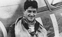
Hello All! Next update for you. Firstly, I would like to thank again Palm-tree again for his messages and information, greatly appreciated! First bit of news is a retrofit I have done on the side walls; After getting into Johnnie's Book and the work he carried out on gunsights, I have opted to fit the Gyro Stabilised Gunsight to her. This cements the version I am building being a late version Mk.IXe To show this I have fitted the following to the side walls; On the Starboard Side Wall, I have added the Terminal Junction Box and Dimmer Switch, highlighted by the red arrow. While I am here, forgot the mention that the Pulley Mechanism on the Undercarriage System (Blue Arrow) is also 3D printed to overcome the original solid moulding on the Airfix Kit. On the Port Side, I added the three Signal Cables from the Throttle Quadrant to the Gunsight (Blue Arrow) Also while I am here, I added the Electrical Junction Box to the lower Bulkhead (Black Arrow) Now we move onto the Floor and Instrument Bulkhead; I thought about the Rudder Assembly which is a little basic on the kit; I thought about Photo etching and 3D Printing but then I found Aircraft in Pixels. https://www.aircraftinpixels.com/ Although they at present only have early Spits in their range, I am able to update the their kits to later marks of Spitfire. I promise there is no commission involved here but I can honestly say that Aircraft in Pixels 3D Printing is the finest I have seen! If it were not for the holding pins, I could swear the parts were cast; not a single layer line anywhere.. Not only is the AinP Set an amazing enhancement but it also allows you to pivot the arms to allow the rudder to be deflected later on as I have done. The photo etching on the Mounting Bracket for the Rudder Arms are from the Buchon Scale Models Kit The top Mounting Plate and Foot Plates are completely rebuilt allowing me to show the plate nature of this area and also add the securing fittings The Bottom of Frame 11 is 3D Printed to show the top holes in the hollow frame The Rudder Pedals are from the original kit (I know, shock) with the foot grips from the Airscale Set The Top Foot Straps are from the Eduard Set Like an absolute fool, I forgot to show the piping on the floor; hope you can see it! Thanks to all of those who helped in this area on my Spitfire Piping Post! The Instrument Panel is Quinta Studio The Bottom Section of the Instrument Frame is from Buchon Models as this has the correct holes in the frame The Rivets around and inside the Footwell Opening are bespoke photo etching The Brass Fuel Pump Priming Assembly is 3D Printed The Fuel Valve Selector Plate and Lever is Airscale with the Arm Shaft Assembly Scratch Built The Compass Bracket is a great addition from the Airscale Kit The Side Plates are Hawaiian Air Depot, converted to etch & the covers for the piping going into the wings (guns etc.) and these save a staggering amount of piping work! The High Pressure Air Distribution Box is 3D Printed as it is missing from the kit I cannot comment on who the woman in the photo is but I can say she is the very special lady in my life who asked me build this Spitfire Now for something a bit controversial... You will hopefully see that I have added grassy mud where the pilot would get into the aircraft. Reading the Service Record of ML407, as she pushed towards Germany, many a makeshift Airfield was used. I know that adding this detail is quite rare but when the diorama is finished that she is going to sit in, all will become clear... The one point I should mention is the Johnnie's Ground Crew took a lot of care and attention with the upkeep of ML407. I have therefore (might not seem like it in the photos) only given her at the moment stress flaking so far and added Airfield Dust in areas that receive very little attention or are hard to get to. Just a little nod to the unsung heroes of our services that keep the pointed edge moving forward to victory... Thanks for looking! Cheers Steve
- 55 replies
-
- 16
-
-

Spitfire Pipework Question...
Crossofiron replied to Crossofiron's topic in Aviation Discussion & Research
Thanks guys -
Spitfire Pipework Question...
Crossofiron replied to Crossofiron's topic in Aviation Discussion & Research
Many thanks! Cheers Steve -
Absolutely mate! Feeling a double build coming on. And an application for an extension on the house to put it
-
Hello All, Got a question regarding some pipework on the Instrument Panel Bulkhead on my ML407; Can anyone tell me where these pipes go from and too or what they are? Many thanks Steve
-
Thanks so much for comments everyone! It means a lot to me... Cheers Steve
-
Thanks so much for the comment! My wife loved that...
-
Hello All, Bit of an update for you; side walls are finished! All the Placards are mostly Airscale (AS24PLA) with some bespoke ones thrown in There are some Quinta Studio Decals here and there like the Radio Channel Selector Cover The Oxygen and Antifreeze valving is all 3D Printed with 0.4mm Brass Rod All bespoke photo etching The Throttle Quadrant is Hawaiian Air Depot concerted to etch The Trim Cable Side Covers are 3D Printed to get the stamped channels represented (missing from the kit) Compressed Air Bottles are 3D Printed to achieve the weld lines and correct size Battery, Terminal Boxes and Light Fittings are 3D Printed Undercarriage System is greatly enhanced by the Airscale Mk.IX Upgrade Set Miniature Brass and Steel Bolts here and there Got the two rear frames in so I can wire up the radio; Thanks for looking!
- 55 replies
-
- 23
-
-
-
1:18 Scale B-17G Flying Fortress Forward Fuselage
Crossofiron replied to patricksparks's topic in Works in Progress
For the love of God! Seriously wow! -
Hello All, So, the Air Frames and Bulkheads. I used several enhancements for the frames; Frame 11 (Seat Frame); There are two Airscale Instrument Panel and Ancillary Kits that I used so I could overlay the etching both on the front and the back I oversized the holes on the kit part so the representation of the hollow frame could be achieved This meant the groove in both sides of the fuselage had to widened to get it to fit properly All the rivets are individually placed as per the fuselage I used Buchon Scale Models BUC24-018 Upgrade as it has some nice enhancement pieces in particular the Voltage Regulator and Seat Removal Mechanisms The Armour Plate Bolts are also handy The Seat Frame Floor Brackets and Pins are scratch built https://www.buchonscalemodels.com/ The 'rough' areas are stippled future polish for me to show aluminium oxidisation, I will locally weather this frame when all the bits are on it. Frame 12; I 3D printed this one so I can put in the perforations which are missing from the original Airfix Moulding. Frame 13; I drilled some more perforations in the frame to start with. Totally understand why Airfix did it bit the plate for the Radio Chassis is moulded into the frame and the Radio Chassis itself has no perforations. No issue unless you want to show off the radio! I modified the Hobartville Hobbies Radio Bay Upgrade for this. https://www.hobartvillehobbies.com.au/ Frame 4 (Footwell); I cut the moulding in half as I want to show off the back of the Instrument Panel Added the Location Brackets for the Upper Section and the Cross Bracing for later Added Cable Socket Inserts Usual individual riveting and some strengthening strips that are missing (only needed if exposing the Fuel Tanks) Firewall; Lots and Lots of Bespoke Photo Etch! Both sides were stripped of all details and then PE added from the skin up. Frame 5 (Instrument Panel); I decided on the Buchon Frame with the Airfix Instrument Shroud on top. This gave me the correct hole placement More PE to replicate the frame mating pressing both front and back Original Thanks for looking!! Cheers Steve
- 55 replies
-
- 16
-
-
Thanks Peter! Wait until you see my next WIP update, couldn't have done it without your enhancements
-
Hello All, Thought I would share a stroke of luck. Firstly, thanks to Palm-tree for messaging me and given me several pointers. Palm-tree sent me photos of his 1/32 ML407 and I have to say it is superb! One of his pointers was to try and get hold of Johnnie Houlton's Book; Spitfire Stikes. A New Zealand Fighter Pilot's Story Well, not only did I buy the book on eBay for £15.00 + P&P but the copy is signed by six WWII RAF Fighter Pilots! RESULT!
- 55 replies
-
- 10
-
-
Thanks for all your kind words everyone!
-
Anthony! Great to hear from you! Going to send you a PM..
-
Hello All, Those of you that have seen my other build of three 1/32 Avro Lancasters will now know that I am still alive, just taking a break.. I have been asked by someone very special to build a 1/24 Spitfire with the subject being The Supermarine Spitfire Mk.IXe, ML407, Sq Ldr John 'Johnnie' Houlton This of course is now 'The Grace Spitfire' The base kit of course is the 1/24 Airfix Mk.IXc Kit. I make no apologies if I call ML407 a she; such a beautiful aircraft with such a wonderful history; Before I start the build thread I need to say that I am totally inspired by Wolf's 1/32 Spitfire build, something to aspire to. THE FUSELAGE HALVES I took the fuselage halves, stripped them down to the level I needed and filled in the ejector marks. The intention is to show both fuel tanks so VERY carefully, I took the armour plating off as well. The TR9 will be shown so I removed the radio hatch door too. First things first was to design my own photo etch; I really wanted to show the hollow frame nature of her; I also used the templates from the 1/24 Spitfire Cockpit Download from The Hawaiian Air Depot Site; https://www.hawaiianairdepot.com/ After fitting the etching, 1,764 Rivets were individually placed using Quinta Studio Rivets of various sizes; She is going to be powered and lit up too so I managed to hide the cables behind the side walls. I am going to feed the power cables through the ground power connection. It was then a spray with Semi Matt Varnish to seal the rivets, a base coat of dull aluminium, chipping fluid then Ammo RAF Interior Green; Hope you like what you see so far, onto the frames and bulkheads! Thanks for looking... Cheers Steve
- 55 replies
-
- 31
-
-
-
Hello all, Really gutted about this message. Family issues means I am going to have to hang up modeler's knife for a while. Apologies for doing this to you again. Mind you, you still have Anthony's build to enjoy! Will be back as soon as god wills... Cheers Steve
