Ironwing
-
Posts
3,872 -
Joined
-
Last visited
-
Days Won
18
Content Type
Profiles
Forums
Events
Everything posted by Ironwing
-
Derek, On page 51 of North American F-51 Mustangs In latin American Airforce Service, Dienst & Hagedorn, Aerofax Datagraph 1, aerofax Inc. 1985 are two very clear pics of the bar you are asking about. I have no way to scan them readily at hand. If you can't find the publication, write and I'll try to get the page scanned for you and post the pic. Geoff
-
Greetings all, Ango: Thanks for the kind words. Believe me, I make alot of mistakes. As far as the vacforming thing; I have an old Mattel Vac-u-Form toy that I purchased many years ago (>20 yrs.). It has lasted to this day. It's a great way to replicate things. Several years back I had to build a larger one to manufacture a new canopy assembly for a 1/32 F-16 A I converted to a B. It has quite a bit more capacity (size wise) than the Mattel, but its size uses up alot of plastic quickly and mistakes become expensive. Having said all this, thanks again and as things progress I'll keep posting. Best wishes, Geoff Chris, Thank you to you as well for your kind words. I work hard at producing something as realistic as possible. Im sure you have the same ethic. But, again I thankyou. I hope all is well, Geoff
-
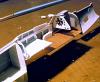
The back end with the door in place and new tail wheel assembly.
-
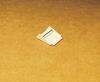
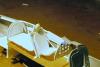
Scratch built inter cooler outlet door. The door is a rather complex little affair. It has two curves, one in both X and Y planes. Obviously the kit part needed replacing to accurately represent the real thing. The new part is hollow. The kit part was used as a master to get the proper bend from side to side. The sides of that part were then cut away leaving only the bottom piece and new side walls were fitted to it. A new inner floor was then made up by first spanning the witdth of the part with a piece of .025 plastic rod. A new inner floor was then welded into place over the rod, which created the required inside curve which is parallel with the side walls of the door. The inner support was made up of Florists wire and Zapped into place between the side walls. This artifact doesn't appear consistently in photos I have studied. Can anyone add to this? The tab on the end of the door engages the fuselage to form a mounting and alignment surface.
-
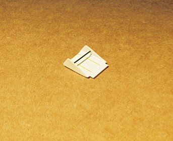
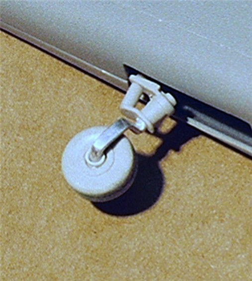
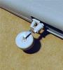
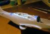
New tail wheel assembly:The strut has an unusual flattened shape through its cross section. This was replicated by squeezing aluminum rod in a pair of flat jawed pliers. This was then bent into the proper shape. Note: the flattened cross section is not carried onto the wheel mounting surface. That remains round.
-
Kit supplied tail wheel: As is it's really not usable for a well detailed model. The support strut and the tire are all one piece. the strut and wheel were cut off. The strut was then sanded away leaving just the wheel and a new strut was fashioned from aluminum tube stock.

-
So much for the seat. Here's the tank roughed out awaiting details. Make sure the tank details dont interfere with the radio boxes.

-
Hey, look at that. How did I do that? i thought double vision only came from Tequila and getting kicked in the head by a donkey.
-
Armor Plate,Front: Flat card stock. The upper portion where it bends forward is first scribed on the back to make the bend easier. A reinforcing piece of card stock is them welded along the scribe line both front and rear to stiffen and support the head rest. The bar running across the width of the plate, Ive read, was a hand hold. I'm not sure about this. I do know for sure that the upper harness belts run behind, up, and over it before they come forward. I think the bar has more to do with the belts than a hand hold. Anyone know the answer to this? In any event, the seat isn't hard to construct. It does take some time and judicious sanding but the effort is well worth it once it's complete.

-
Rear of armor plate/seat support: Again just plain card stock, all flat cut and sanded to shape. The seat articulates with the two double verticle seat supports on either side of the plate. The supports pitch the plate aft. This requires the upper section (where the head rest is) to be bent forward in order for it to stay perpendicular to the floor. The antennae attachment point behind the headrest is from the Eduard Mustanf Detail Set. I mounted it on a piece of .005 card stock then mounted it to the back of the headrest to give it a bit more relief. Many of the components in the Eduard set, at least in my opinion, aren't really of much use without some sort of help. The placard set is much more useful.
-
Rear of armor plate/seat support: Again just plain card stock, all flat cut and sanded to shape. The seat articulates with the two double verticle seat supports on either side of the plate. The supports pitch the plate aft. This requires the upper section (where the head rest is) to be bent forward in order for it to stay perpendicular to the floor.
-
Seat assembly with springs: These springs assisted the pilot in raising and lowering the seat. In this instance, they are made of .020 solder which has been wrapped around a separate piece of rod stock tightly then removed and pulled open. This is then cut into two pieces and the two resulting pieces are slid over each vertical member on the back of the seat. The verticle rod attached on the center line of the seat back is the the harness attachment point. The edges of the seat are feathered into the rod stock to create a radius which makes it look like one continuous piece from the front leaving the seat risers in place on the back.
-
Some of you have expressed interest in the seat and how it was made. Its quite straight forward. Aside from the bucket which was vac-formed over a wooden mold (quite rudimentary) it's all card and rod stock with the exception of the slight bend in the backrest. The Evergreen rod stock (which earlier I said was .030" is actually .047. It bends easily and welds quickly into place. Leave extra length at the bottom. The seat attaches to the floor via the verticle members as well as to the armor plate.

-
Bill, Perfect! A very big help indeed. There are some new shots going up - The beginning of the panel is included... Geoff
-
help is always welcomed...thanks
-
bsarnoffca, Sorry, I didnt mean to ignore you in my last post, Thank you for your kind words. I genuinely appreciate them. I'll definately post the panel and the rest of the interior as soon as they are complete. The Mustang panel isnt very exciting. Its black on black functionality, lends itself to a rather plain appearance. I have some detail drawings of some warning lights that might "colorize" things a bit, but for the life of me, when I look at photos of the panel, I cant figure out where they are. Have any idea where they are supposed to be? In any event, thanks and be well. Geoff
-
Piet, Dave, Jimbo and Derek, Thanks for your compliments, nice to know others appreciate it. Dave: To manufacture the seat, I used the pics that Coolie posted over in Discussion as a guide, they were an immeasurable help. It's relatively straight forward. The bottom tube is formed from a wooden plug (balsa) sanded to shape then vac-formed. The back rest is a flat piece of card stock which is trimmed on its edges, with .030 (1 mm) Evergreen rod stock. After the weld has dried, the joint between the rod stock and the back rest are feathered together to eliminate the seam and make it appear as one continuous surface. The tub is then attached to the bottom. Once this is completed, the seat back is bent slightly to achieve the requisite curve. It doesnt take much; the curve is subtle, like everything else on the Mustang. The armor plate behind the seat is flat card stock dressed up. The only aspect of the armor plate which adds a bit of a twist is the angle that it sits at while it's in the cockpit and keeping the headrest verticle. This requires a scribe line to be added at the top (where the headrest is) and a slight bend to be made along that line to achieve the proper angle for it. I also used one of the PE pieces from the Eduard detail set to finish the back of the headrest (wire antennae attachment plate). The Eduard set for the Mustang has some helpful pieces but its overall accuracy isnt all that good. The parts are made to fit the kit parts which, for the most part, are incorrect. As such, the Eduard PE part mentioned is just too thin. I mounted it on a piece of .005 card stock with Zap, sanded the edges clean then mounted that on the back of the head rest.I'll shoot some pics and post them but it will be a few days before I can get that done. I dont have a digital camera and must rely on 35 mm film, then have them put on a disk by the processor. Laurent Boulestin posted some seat pics with dimensions which, again, were of great help. The posting is in Discussion (5-17-06) under the heading "New Question for Craig and Laurent." Derek, Good to know your working on a Mustang. You understand the issues that must be dealt with in the Hasegawa kit. I've been working on the intercooler assembly and the exit door. again, alot of building to get the area squared off (had to add panels to the fuselage sides). Hasegawa's rendering has the assembly tappered. This is totally wrong. The Eduard PE part follows that taper. No good. The kicker is the door itself. The darn thing is hollow and has a slight curve in both the X & Y axis. Much fun making it (hysterical laughter and head butting the wall) but it's done, I think. Lets see some of your Mustang and hear about some of your techniques. Piet: Not much to say, I've seen your work here on LSP and find it remarkable. Your comment about the seat I take as an extreme compliment. Many thanks. Jim, Hobby Masters is waiting Dude. Be well all, Geoff
-
Jean, Absolutely remarkable detailing. By all means, do continue to post. Im amazed at the detail level that you achieve. Simply superlative work old boy. Geoff
-
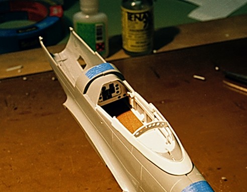
Other interior details.
-
The seat in place. Work has begun on the panel which can be seen from the back side. I put the bezels in place (on the other side) then drill open the holes. To final fit the openings for the instruments, I use a conical burr on the backside to bring in the final fit and avoid hitting the bezel itself.
-
another try.
-
The total filespace required to upload all the attached files is greater than your per post or global limit. Please reduce the number of attachments or the size of the attachments. whats this?
-
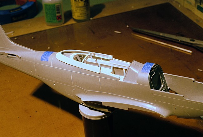
Canopy frame looking aft: Note how the frame, when it is in the full aft position lies along side the outer fuselage walls.
-
Piet, Thanks for both your comments and compliments. They are always welcomed. I think the canopy mistake is a common one which is caused by the way the guides force the canopy to apparently go. In actuality, the frame pivots in the canopy rails which allow it to drop down in back. It then follows the grove on the dorsal spine.
-
Canopy frame on fuselage: This shows the proper position for the canopy assembly. Also visible is the beginning of the instrument panel