Kenneth Joy Posted August 22, 2021 Share Posted August 22, 2021 Glad to hear everyone is doing better! Link to comment Share on other sites More sharing options...
Victor K2 Posted August 23, 2021 Share Posted August 23, 2021 Ditto Link to comment Share on other sites More sharing options...
tomprobert Posted September 2, 2021 Author Share Posted September 2, 2021 Morning all, A little more progress to share on the Sunderland - I've been working on the engines of late which has not been the most fun (I hate engines and cockpits!) but I'm at a stage where they are ready for installation to the airframe. Sunderland IIs were powered by the Bristol Pegasus, of which aftermarket options were very expensive and to fit four to model would have cost me nearly £100! Therefore I did originally plan to modify the Revell 1/32nd Hercules engines from a Beaufighter, but being two row seven cylinder engines, that was going to be quite a challenge. With the Pegasus being a single row nine cylinder set up, a better starting point would have been a Wright Cyclone and thankfully a fellow forum member came to the rescue (thanks, Mark!) and sent me a set of his unused HK Models' B-17 engines. The reduction gear housing more closely resembles the Hercules set up, however, so I used the HK cylinders and the Revell Hercules reduction gear - not perfectly correct but close enough... The Pegasus is actually, at least at first glance, a quite simple engine to replicate (used for illustration purposes only): I won't have to worry about detailing the cylinder heads as these will all be hidden by the cowling, so it would just be a case of adding the single push-rods. First up I sprayed the inside of the cowlings black and then I needed to check the cylinders fitted inside the cowlings properly - in the picture below you can see they sit quite happily in the correct position and actually needed no glue to hold them there. The reduction gear housing is just sitting on the cylinders to get the 'sit' of the engine correct in regard to clearance for the propeller: I then painted the cylinders and reduction housing, and made the pushrods from Evergreen before adding and painting: A final test fit in the cowling - as you can see not much can actually be seen so the detail I've added is quite adequate: All four 'power eggs' are now complete, with the engines secured with Araldite Epoxy to ensure they don't fall into the nacelle: Next up will be installing these onto the wing... stay tuned. All the best, Tom KiwiZac, patricksparks, dodgem37 and 21 others 24 Link to comment Share on other sites More sharing options...
alaninaustria Posted September 2, 2021 Share Posted September 2, 2021 Wow! Very nice! You're the master modeler Tom! Cheers Alan tomprobert 1 Link to comment Share on other sites More sharing options...
Out2gtcha Posted September 2, 2021 Share Posted September 2, 2021 Love it! tomprobert 1 Link to comment Share on other sites More sharing options...
Anthony in NZ Posted September 2, 2021 Share Posted September 2, 2021 Wonderful progress and thinking outside of the box. Love the Sunderland, you know I am going to be insanely jealous of you when this is done! Derek B and tomprobert 1 1 Link to comment Share on other sites More sharing options...
blackbetty Posted September 2, 2021 Share Posted September 2, 2021 that looks fantastic! tomprobert 1 Link to comment Share on other sites More sharing options...
Oldbaldguy Posted September 2, 2021 Share Posted September 2, 2021 “The detail I’ve added is quite adequate.” You, sir, are a master of the understatement. tomprobert 1 Link to comment Share on other sites More sharing options...
brahman104 Posted September 3, 2021 Share Posted September 3, 2021 Wow!!! You made quick (but amazing) work of those engines, they look great Tom! Glad you were able to come up with such a neat and resourceful solution. Craig tomprobert 1 Link to comment Share on other sites More sharing options...
tomprobert Posted September 3, 2021 Author Share Posted September 3, 2021 19 hours ago, Anthony in NZ said: Wonderful progress and thinking outside of the box. Love the Sunderland, you know I am going to be insanely jealous of you when this is done! Well I suggest you crack on and get your Brit Toom finished and order yourself a BIG Sunderland for your next project! I got the engines attached to the wings last night, so hopefully some pictures over the weekend - all being well. Tom Troy Molitor and Anthony in NZ 1 1 Link to comment Share on other sites More sharing options...
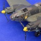
tomprobert Posted September 5, 2021 Author Share Posted September 5, 2021 Evening boys and girls, It's been a glorious sunny day here in my corner of Kent so I got the camera out and snapped some pictures of the recently installed engines. With each 'power-egg' complete it was just a case of adding them to wing-section of each nacelle. The Revell Beaufighter cowl flaps were an absolutely perfect fit for the kit's forward firewall, so it was just a case of applying some Araldite to the inside surfaces of the cowl flaps and sliding them into place. The relatively slow drying time of the epoxy glue meant I had ample time to ensure each engine was aligned correctly, both with the plans and each other. When installing them, I didn't realise that the engines canted outboard at such an angle, but references confirmed this was the case. It certainly looks a little strange that the thrust line is so off central, and I presume there is a valid reason for it, too! Anyway, on to the pictures... As you can see the fit is nice and snug, and engine no.1 looks the part now it's hung on the wing. The early MkII-style straight exhausts will be made and added later: Engines 3 and 4 - lots of care was taken to align the engines carefully during installation: When I was hacking about with the kit-supplied nacelles I removed and kept the very crude carburettor intakes in the hope I could make something useable from them - as you can see from the three finished intakes at the top of the picture they scrubbed up fine: These were than glued in position on the lower section of each nacelle: She's really starting to take shape now: Thanks for stopping by folks, and stay safe! Until next time, Tom dodgem37, Troy Molitor, chukw and 21 others 24 Link to comment Share on other sites More sharing options...
brahman104 Posted September 5, 2021 Share Posted September 5, 2021 Definitely looking the business now Tom, great to see the engines on! Craig Link to comment Share on other sites More sharing options...
Troy Molitor Posted September 5, 2021 Share Posted September 5, 2021 Most impressive Tom. She really looks the part. Link to comment Share on other sites More sharing options...
Derek B Posted September 5, 2021 Share Posted September 5, 2021 Nice work Tom Derek Anthony in NZ 1 Link to comment Share on other sites More sharing options...
mozart Posted September 5, 2021 Share Posted September 5, 2021 Wow Tom, simply stunning. She’s going to look great with some paint on her, what are your thoughts about weathering? tomprobert and Anthony in NZ 2 Link to comment Share on other sites More sharing options...
Recommended Posts
Create an account or sign in to comment
You need to be a member in order to leave a comment
Create an account
Sign up for a new account in our community. It's easy!
Register a new accountSign in
Already have an account? Sign in here.
Sign In Now