Cheetah11 Posted December 15, 2018 Share Posted December 15, 2018 (edited) Hi Everyone Here is the subject. A Gulf War Tornado F3. This project has been lingering on the shelf of doom since 2003 and I decided it is time to finish it. I had an extra Revell 1/32 Tornado (long story) and after reading Desert Fist by Ian Black, I decided a Tornado F3 would look good in 1/32. Ian was a F3 pilot in the first gulf war and the majority of the photos in the book was F3 photos. This looked like an easy conversion at the time , but as each stage progressed, the problems to solve became a little more difficult. I used photos from the book to measure the plugs to be inserted and then proceeded to cut and paste the model. When I later got the proper measurements from another publication, I had to revise the plugs slightly. I also lend the book to someone, and then could not remember whom it was. Eventually about a year ago I decided it is now time to finish the beast. The idea was to do all the changes applicable to the F3 and keep the detail of the rest of the kit OOB. These are the basic changes to the kit. The nose was cut from a plastic card block turned in a power drill . Here it is primed and next to the GR1 nose. More to follow soon. Nick Edited December 16, 2018 by Cheetah11 spelling blackbetty, LSP_Kevin, Uncarina and 8 others 11 Link to comment Share on other sites More sharing options...
LSP_K2 Posted December 15, 2018 Share Posted December 15, 2018 Nice. I've really been thinking about getting started on my Saudi Tornado. Out2gtcha 1 Link to comment Share on other sites More sharing options...
ericg Posted December 15, 2018 Share Posted December 15, 2018 Good to see Nick. Will follow you build, and hopefully you will dig up some good pics of the rear cockpit as that is why I paused building mine! eric. Link to comment Share on other sites More sharing options...
Stevepd Posted December 16, 2018 Share Posted December 16, 2018 Great another tornado. I’d read a couple of years ago about a conversion and you’ve made the wrongs right. Been on the shelf since 2003! now that’s faith in a project. I’m doing a GR1 at the mo and I’m at a decision point on which way I go for the finished article. Steve. Cheetah11 1 Link to comment Share on other sites More sharing options...
Cheetah11 Posted December 16, 2018 Author Share Posted December 16, 2018 Hi Eric I was wondering what happened to your build. The lack of photo references also kept this build stalled for a long time. Eventually I decided to go with what I had or bin the project, so a bit of artistic licence was called for in some cases. I think the main problem was that a number of updates were done to the F3 during its life especially the cockpit. I found many photos during the latter part of it's life but few of the Gulf War era and fewer still of the aircraft during the Gulf War. A time before cameras on cell phones. The photos in Ian Black's book is mostly airborne shots, so not as usable for modeling as one would like. I am sure you will go into a lot more detail during your build, so let me know if you need some reference. A modelling friend of mine visited 11 Sqn around 1999 and was fortunate enough to be allowed to take some photos of things like the gear bays and cockpit which I can let you have. Nick Link to comment Share on other sites More sharing options...
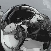
Cheetah11 Posted December 16, 2018 Author Share Posted December 16, 2018 (edited) The nose gear and doors of the F3 is quite different from the srtike version. This is to accommodate the recesses for the missiles. I modified the front gear doors by sanding them to shape. The rear door on the GR1 is tapered but not on the F3. To preserve some detail I cut a V-section from it and re-glued it together with a thin plastic card backing. The nose gear was modified from the kit parts by removing the rear torque-link and making a new one in the front, using the photo as reference. A piece of plastic card was glued in the bay to facilitate the fitting later on. Completed and painted. Comments welcome Nick Edited December 16, 2018 by Cheetah11 Fvdm, Shawn M, Pfuf and 6 others 9 Link to comment Share on other sites More sharing options...
crobinsonh Posted December 18, 2018 Share Posted December 18, 2018 On 12/15/2018 at 11:12 PM, ericg said: Good to see Nick. Will follow you build, and hopefully you will dig up some good pics of the rear cockpit as that is why I paused building mine! eric. Did you checkout: https://www.jetartaviation.co.uk/what-we-do/aircraft/ and http://www.aircrewinterview.tv/david-butterfield-engineering-technician-airframes/ Link to comment Share on other sites More sharing options...
Madmax Posted December 19, 2018 Share Posted December 19, 2018 Some lovely detail work on the nose gear leg Nick. The torque link is particularly impressive! Link to comment Share on other sites More sharing options...
Cheetah11 Posted December 19, 2018 Author Share Posted December 19, 2018 Thanks for the compliment Sean . I was surprised myself that at my age I could glue the small strips on the side of the torque link without messing it up. One of the marked differences between the GR1 and F3 is the rear cockpit. The Revell kit also have a few short-comings even for a GR1. The most obvious is that there is no sill to the cockpit and the front instrument panel is two dimensional whereas the real aircraft has some parts proud of the main panel. Even though I did not intend to detail the model past OOB detail I felt these details had to be addressed. The rear cockpit has a different layout of the displays and IP compared to the GR1 and is offset to the right (starboard for the naval types). Eyeballing these from the photos I made a new back IP and screens and adjusted the front one a bit. The front IP is from the ECR boxing which is closer to the F3 than the GR1 boxing. I also noticed the panel lines on the F3 forward fuselage is slightly different from the kit panel lines. Not sure if there is a difference between the real aircraft but I chose to ignore most of this. I only re-scribed the refueling probe panel and the panel over the gun port which is quite distinctive. Nick Daniel Leduc, Anthony in NZ, Alain Gadbois and 3 others 6 Link to comment Share on other sites More sharing options...
AlanG Posted December 19, 2018 Share Posted December 19, 2018 Ah i love the smell of OM-15 in the morning! Good old Riggers Blood! I really want to build a GR1 and GR4. I did have two kits years ago but had to sell them due to financial difficulties. Great start so far and shall be watching this build Link to comment Share on other sites More sharing options...
Wegener Posted December 19, 2018 Share Posted December 19, 2018 Good work so far and encouraging that the ECR (which I snaffled at a silly price a couple of years ago) is a better F3 starting point than the GR1 too, as that’s what I was planning for it. Once Tim finishes his parts anyway.... Link to comment Share on other sites More sharing options...
Cheetah11 Posted December 21, 2018 Author Share Posted December 21, 2018 Here is a little more work done on the cockpit. The rear IP is slanted slightly forward and the Revell kit IP is vertical, so a small adjustment needed to be made. This impacted on the Paragon (how many remember those AM parts) ejection seat fit when test fitted , and I had to use the Dremmel to adjust the seat slightly. Just a general comment on the IP and cockpit. The instruments and dials are most likely scale but in 1/32 this leaves them very flat and difficult to dry brush and get detail visible. Wegener I would try and get the IP from Tom The ECR boxing is the better kit IP to use but suffer from the same restrictions as the rest of the cockpit. I saw the IP the Tom made on Eric's thread and they appear to be much better. Anyone contemplating building an 1/32 should try and put some pressure on Tom to finish the conversion(Sorry Tom!) Anyway here is the adjustment to the cockpit and test fit in the fuselage. Enjoy Nick Out2gtcha, LSP_Kevin, Alain Gadbois and 5 others 8 Link to comment Share on other sites More sharing options...
Cheetah11 Posted December 22, 2018 Author Share Posted December 22, 2018 (edited) The normal practice when this kit was made was for models of swing-wing aircraft to follow full size practice and be movable. This creates a problem at the wing seal position as the plastic cannot flex as full size counterparts. The Revell kit is a bit unrealistic and needed to be fixed. I used 0.25 mm plastic card and scribed lines 1 mm apart on them. This was then cut to size and ruffled as per full size before gluing in position. And once primed. I also used the time to deepen the panel lines at the flaps and slats. Many models ( Like the Dragon Me110) have panel lines that are of equal depth which is unrealistic as the movable parts like ailerons, flaps and slats have larger and deeper demarcations. Enjoy Nick Edited December 22, 2018 by Cheetah11 Additional text added johncrow, Greg W, LSP_Kevin and 5 others 8 Link to comment Share on other sites More sharing options...
Stevepd Posted December 22, 2018 Share Posted December 22, 2018 Nick, good of progress and detail. My wings are fully forward and I used backing plastic and then plasto filler, whilst it was still wet I scored it which is not a million miles away from yours. Anyway I’ve attached the undercarriage and my nose leg gear looks extended akin to a phantom on an aircraft carrier launch. I see you’ve done yours - did you cut and shut yours?. I’ve scaled up from a set of 1/72 drawings and the MLG looks good but the MLG kit wheels are oversized and the NLG is way over. Any advice to confirm what I’ve got would be appreciated. Steve. Link to comment Share on other sites More sharing options...
Cheetah11 Posted December 23, 2018 Author Share Posted December 23, 2018 Hi Steve 10 hours ago, Stevepd said: Nick, Anyway I’ve attached the undercarriage and my nose leg gear looks extended akin to a phantom on an aircraft carrier launch. I see you’ve done yours - did you cut and shut yours?. Any advice to confirm what I’ve got would be appreciated. Steve. I have also build a German ECR and had to reduce the length of the nose oleo to make the model sit correctly. I think Revell modeled the nose gear with the oleo extended. The only way to get the correct sit will be to reduce the length of the nose gear oleo. I think the nose wheels are a bit over sized but I will still used them. Nick Link to comment Share on other sites More sharing options...
Recommended Posts
Create an account or sign in to comment
You need to be a member in order to leave a comment
Create an account
Sign up for a new account in our community. It's easy!
Register a new accountSign in
Already have an account? Sign in here.
Sign In Now