Anthony in NZ Posted June 24, 2016 Share Posted June 24, 2016 Agree with Alain, absolutely sensational! allthumbs 1 Link to comment Share on other sites More sharing options...
ClumsyDude Posted June 24, 2016 Share Posted June 24, 2016 This is some inspirational work, great stuff! Jim allthumbs 1 Link to comment Share on other sites More sharing options...
ChuckT Posted June 25, 2016 Share Posted June 25, 2016 Amazing work here Rich, very impressive! One questions though about the HGW rivets, which size are you using for this? They look great. Thanks in advance, Chuck. allthumbs 1 Link to comment Share on other sites More sharing options...
ChuckT Posted June 25, 2016 Share Posted June 25, 2016 While I have you, would you mind explaining your technique for super smooth scribed lines? They look incredibly sharp! allthumbs 1 Link to comment Share on other sites More sharing options...
airscale Posted June 25, 2016 Share Posted June 25, 2016 stunning, stunning detail - a joy to watch I love it when a subject is covered like this - and those are some galactic skills you have there most enthralling Peter allthumbs 1 Link to comment Share on other sites More sharing options...
Marcel111 Posted June 25, 2016 Share Posted June 25, 2016 Beautifully clean and crisp enhancements, simply wow! Cheers, Marcel A-10LOADER and allthumbs 2 Link to comment Share on other sites More sharing options...
wardog Posted June 26, 2016 Share Posted June 26, 2016 Hey Rich, Great update as usual and always worth the wait. As you know, I'm not a 32nd scale enthusiast, however I always look forward with great anticipation to all of the updates on this build. One thing is for sure, when you make updates it's literally "class is in session " as I carefully read all the information to try and absorb all the knowledge you're providing. As always...awesome work and definitely the best I've seen! Elmo allthumbs 1 Link to comment Share on other sites More sharing options...
allthumbs Posted June 26, 2016 Author Share Posted June 26, 2016 (edited) Kev, Patrick, Alain, Anthony, Jim, Chuck, Peter, Marcel, Elmo... Thanks a bunch for all the kind responses. Very humbling, especially as it comes from some of the world's best 🙂. Chuck - I used HGW's 1/32 series rivets, an early set printed in black, that was purchased a couple of years ago. Their newer sets I notice are silver colored. I'm not sure, but I think the "formula" is the same. I'll test 'em out and let you know. Hopefully, my reply (and those of others) on the "General Discussion" thread http://forum.largescaleplanes.com/index.php?showtopic=63193&do=findComment&comment=810749 offered some additional insight. Bear in mind, I've only used these products sparingly, across small areas. I've yet to cover an entire airframe with them. I still consider myself a rivet neophyte 😉. Regarding panel line scribing: my "weapon of choice" continues to be a sewing needle (slightly dulled) chucked into a 4-jaw Xacto style hobby knife handle. Dymo labeling tape provides a nice edge or "backstop" for the scribe. Invariably, I'll experience "chatter" along the line as the needle hiccups its way across the surface (as if encountering pot holes along a road). Such blemishes are often so minor as to be ignored. But when they becomes a bother, I'll run a homemade slotting file along the engraved line. This helps to smooth things out a lot. I simply take some fine grit sand paper (600 to 1000) and super glue it to some scrap sheet plastic - thin stuff like .010." When the glue is dry, I cut a fresh, beveled edge into the laminate. Run this tool along newly scribed grooves to clean them out and even up their look. The following images illustrate the process... Up-close image of results on a scrap test piece... In a sense, this is the mechanical equivalent to "chemically" treating panel lines with a plastic solvent, such as Tamiya Extra Thin Cement. Success can be had with either (or a combination of both) methods. HTH's Rich Update...link to published article in Large Scale Planes website...https://www.largescaleplanes.com/articles/article.php?aid=2751 Edited May 31, 2020 by allthumbs link to LSP article in "Tips & Techniques" section NavyF4s, Harold, Anthony in NZ and 1 other 3 1 Link to comment Share on other sites More sharing options...
ChuckT Posted June 26, 2016 Share Posted June 26, 2016 Very interesting Rich, I never would have though of that! Thanks so much for sharing. How long does this poor man's slotting file last and do you run it along both edges of the groove? allthumbs 1 Link to comment Share on other sites More sharing options...
Starfighter Posted June 27, 2016 Share Posted June 27, 2016 Great to see you are back, Rich - this update was certainly worth the wait! Thanks for the heads up regarding the raised panels; I mostly use self-adhesive copper of aluminum foil but the MonoKote film seems to be a very interesting alternative as it is not always easy to apply the metal foils without wrinkles. I really like the idea of using decal film for slightly raised panels - I'll definitely give that a try! I absolutely love your new football - the spacing between the fasteners looks much better now IMO. The rudder looks stunning as well - which material did you use for the wedge shaped interference plate? I was thinking about cutting a slot into the rudder and sliding the plate into that slot. allthumbs 1 Link to comment Share on other sites More sharing options...
allthumbs Posted June 27, 2016 Author Share Posted June 27, 2016 (edited) Very interesting Rich, I never would have though of that! Thanks so much for sharing. How long does this poor man's slotting file last and do you run it along both edges of the groove? Chuck, I find that they last a long time. However, when they do wear out, you can cut a fresh bevel and it's as good as new. I didn't make mention of it in the first post, but I start with a piece of plastic card that's about one inch square (picture a guitar pick). This allows for more than one beveled edge to be created, thus extending its life further. And yes, I do address both sides of the panel line with the "file." I realize that a picture is worth (at least) a thousand silly words. So, when I get home tomorrow, I'll post photographs of my set up. Thanks for your interest in the project! Hope this helps, Rich Edited June 28, 2016 by allthumbs Greg W and A-10LOADER 1 1 Link to comment Share on other sites More sharing options...
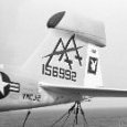
allthumbs Posted June 27, 2016 Author Share Posted June 27, 2016 (edited) On 6/27/2016 at 1:52 AM, Starfighter said: Great to see you are back, Rich - this update was certainly worth the wait! Thanks for the heads up regarding the raised panels; I mostly use self-adhesive copper of aluminum foil but the MonoKote film seems to be a very interesting alternative as it is not always easy to apply the metal foils without wrinkles. I really like the idea of using decal film for slightly raised panels - I'll definitely give that a try! I absolutely love your new football - the spacing between the fasteners looks much better now IMO. The rudder looks stunning as well - which material did you use for the wedge shaped interference plate? I was thinking about cutting a slot into the rudder and sliding the plate into that slot. Hi Ben, As always, thanks for the kind words. I'm not convinced that Mylar film is the answer, but it seemed to do the job in this instance. Metal appliqués I would think offer at least two advantages; better malleability to conform to complex curves; and the ability to take embossing, say from a beading tool or needle. The HVAC tape I have on hand (I think it's aluminum) has a poor quality adhesive. That was the main reason for going with Mylar. I plan to invest in some new foils though, and carry on with the experiment. For the interference plate, I marked its location on the rudder with a scribed line before creating the groove with a razor saw. The scribed line helps keep the saw going straight. The plate itself is made from .015 inch plastic card. A thickness of .010 inches would probably have been more to scale, but I was concerned about strength, as, being an extremity, it's rather exposed to damage. After the plate was cemented into the slot, a .005 inch thick styrene flange was set in place and secured with Tamiya ETC. I only discovered this recently, but when Prowlers (and some Electric Intruders too) received the ALQ-126 "beer can" antenna mod, the fairing at the base of the rudder changed shape - from a small rectangular cross section to a broader, more circular aspect. Trumpeter's design, a hybrid of sorts, is not strictly accurate for either configuration, although it more closely resembles the original "stock" Intruder (and early Prowler) tail. I took a sanding block to the sides of mine to square it up a little more. These pictures help illustrate the difference... Cheers, Rich Edited May 30, 2020 by allthumbs HerculesPA_2, Starfighter, Greg W and 1 other 4 Link to comment Share on other sites More sharing options...
F`s are my favs Posted June 27, 2016 Share Posted June 27, 2016 Small differences and huge differences at once allthumbs 1 Link to comment Share on other sites More sharing options...
ChuckT Posted June 28, 2016 Share Posted June 28, 2016 Thanks Rich for the info. Looking forward to more pics and build updates when they happen. allthumbs 1 Link to comment Share on other sites More sharing options...
allthumbs Posted June 28, 2016 Author Share Posted June 28, 2016 Small differences and huge differences at once Indeed, details, details, details... As an aside, I just posted an illustrated tutorial on how to clean up panel line engravings with a "Poor Man's Slotting File" http://forum.largescaleplanes.com/index.php?showtopic=63256 Thanks for tuning in! Rich F`s are my favs 1 Link to comment Share on other sites More sharing options...
Recommended Posts
Create an account or sign in to comment
You need to be a member in order to leave a comment
Create an account
Sign up for a new account in our community. It's easy!
Register a new accountSign in
Already have an account? Sign in here.
Sign In Now