

Impatient Pete
-
Posts
231 -
Joined
-
Last visited
Content Type
Profiles
Forums
Events
Everything posted by Impatient Pete
-
The Mig- 31 Inerceptor code named "FIREFOX"
Impatient Pete replied to Wbnemo1's topic in Works in Progress
Wow! This project is incredible! I take it you are using some kind of CNC and laser cutter for some of your parts? If so I need to ask you a few questions about laser cutting. Keep up the great work. Pete out -
Lookin good Jens! Was the spine of your kit warped? Mine was. It is caved in pretty badly. What should be a straight line is a serious curve. Oh well, beats scratchbuiling. Your is looking nice. Keep it up. Pete
-
I can't believe all the interest in this old project. Thanks guys. I haven't worked on it for a while now. But I did dust her off and take an inventory of where the project is at. Maybe I'll get some of the little dogging things done over the next break. Pete
-
Thanks for all the compliments guys! Pete
-
Wow...sweet looking panel. Can you give us the particulars on its construction?
-
Dudes! I got the sweetest thing in the mail today. Straight from Mr. Tom O'Hara at the Flying Leatherneck Aviation Museum in Sunny San Diego, CA (Mirimar to be exact) is a CD containing all the pics I could need to make the cockpit right! It also has some great pics of the outside of the plane. Basically, I asked for any pics of details that differentiate the B from the other recce Rhinos. This guy has really come through for me and I owe him a beer at the least. These are great pics. I need to ask him if I can post them and then maybe I can throw some up here. Not that any of you will need them because the R-B was such an oddball, but... I can't wait to get back on it. School is in full swing now, but soon it will be back on the table. Pete out
-
OK, so not really an "update", but a check in. I haven't really done any work, but I did make progress. Thanks to Tom O'Hara at the Flying Leatherneck Aviation Museum in San Diego, I will soon be getting my hands on some good pics of their RF cockpit. It has been stripped, but may still point me in the right direction with regards to the inside structure around the back seat area. I also obtained the Eduard set for the 1/48th Hasegawa kit and it helped me build the rack to the left of the back-seaters seat. Well I just wanted to check in and let my fellow F-4 GB mates know that I am still on the case. How are you guys doing? Gotta go, friends are here for dinner,. Pete
-
Oh MAN! NOOooooooo Sorry to hear about your accident STUS. The other stuff looks great though. I'm going to PM you on a way I might help with your pit rebuild. Keep at it buddy! Don't let it stop you, because it looks good and trust me, your second pit will be better than the first. Pete
-
Looking good... What a beautiful airplane huh? What are your impressions of the Tamiya kit? Pete
-
Thanks for the compliments guys. I am in the process of writing instructions for the intakes, for those who want to do it. They are not hard...really. Aside from the test fitting if the sheet part, they haven't taken that long to get to this point. STUS, the seam is not visible at all. The compressor part needs only slight modification. In fact, if you don't make the compressor blades, you can use the kit piece, but you need to cut it out (veeerry easy) and add it to the back of the intake ring. It will make sense when I post more pics. School just got really busy for me, so my posting will slow down a little. Not too much though. I am just becoming more efficient. To anyone who wants a copy of the pattern, let me know if you can open vector (AI) files. I will post better pics on exactly what needs to be done, but here is a quick explanation: Cut the engine bulkhead in half so each half gets glued to each fuse half. Cut out the turbine face from the bulkhead. I used a 1" circle template and a needle in a pin vise. By positioning the template over the blade disc and making repeated circle passes with the needle, you will eventually cut out a perfectly round 1" hole. Glue the bulkead in place, taking care to keep it perpendicular to the centerline of the fuse. Fit the intake rings into the holes (but don't glue them yet). Some sanding in the holes might be needed. Add the lip to the front of the kit engine inlet face pieces (as seen in the pic above). The sheet intake pieces are rolled around the outside of that lip. The aft end of the rings fit in the holes in the bulkhead. I used liquid cement to glue the sheets. I applied some cement to both areas that would overlap and let that sit a little bit (20 or 30 seconds). I did that so that cement wouldn't leak out and glue the intake to the ring. I rolled the intake and taped it over the ring and let it set. That's pretty much "it". The rings go in the holes in the bulkhead, and the intakes slip over the lip on the rings. I found that the sheet conformed to the inside of the kit intakes best if I pressed on the edges of the sheet that are sticking up, not on the inside of the intake. That's it. Let me know how it goes and don't hesitate to ask any questions that might come up. Oh, and there will be some fitting and trimming and sanding to get the kit intake pieces to fit over the splitter plate and rolled sheet intake parts, I just haven't arrived there yet. Maybe someone will beat me to it! Pete
-
Quick lowdown on how I did it. Fun fun fun!
-
Dudes, I just finished making the patterns for the intakes. They are made out of .010" sheet and are pretty basic. If anyone is interested in making full intakes, let me know and I can send you the file for the pattern. Oh, you don't HAVE to make the turbine faces to do it. But there is a little extra work involved in setting up the kit parts. I'll post some pics later. Pete

-
The tubes that I used are .280" and .340". The smaller size is a permanent part of the assebly fixture, and the blade hub is a short length section of the larger size that slides over that, to which I glued the blades. As long as they are telescoping, the size can be adjusted to suit your needs. It is stock evergreen styrene. The ring is just loop of small diameter rod that I pre-bent by running it over a paintbrush handle. Then I found a piece of tube about the size of the ring I wanted and wrapped the rod around it. By holding the rod tightly wrapped then pressing down on it with a blade, you cut off a ring of styrene. Then I glued the ends together. The more times you wrap it, the more equal rings you get. Pete
-
Hi STUS, The length of the twist was about 7 mm while under tension, then after I ran it under hot water and then let it go, it relaxed to about 25 mm. Though I will say that the length of the twist isn't really important. At first I though that the twist should be the same length as the blade, but then I realized that as long as the twist is constant, it didn't matter. Due to the fact that I was cutting a section out of a piece with a constant twist, they would all be the same. I used .015" by .100", though I would have prefered a more narrow strip. Maybe .015" or .010" by .090". Thanks for the compliments. I only tried it because of the great work that you did on your exhausts. Seriously, this place is such a great source of inspiration. Don't ever think that you're asking too many questions, that's how we drive each other's abilities forward. Pete out
-
And the two finished engine faces. Oh how I wish to see them Spiinnnnnnn! Does anyone know where I can get a high quality recording of a J79 start sequence? I tried the net, including an F-104 site, but found nothing. Maybe I need to make a field trip somewhere...hmmm.. Pete
-
Oh shoot! Sorry. You foreigners all look alike to me Pete
-
Thanks Ango, Thanks STUSBKE (Frederick) and Piet and all the guys here on LSP too! They are my inspiration. That and the turbine idea was Fredericks afterall... Seriously though, thanks. Here is another installment on the turbines. I built the second one using Fredericks method directly. That is, I glued the blades to the hub straigh up and down. But then, after they were dried (and re-inforced at the hub joint) with a little CA, I sanded the root end thin using a flex-i-file. It was really easy and even left a little raised area at the root that looks realistic. Then, I went back and twisted all of the blades 90 degrees. They sprang back a little, but still look like blades. Anyway, here they are: Cheers, Pete
-
I've stepped away from the pit, awaiting some references (actualy, the Eduard set in 1/48th scale, which looks very nice- They definitely did their homework). I messed around with the turbine face, inspired by Frederick and Piet (thanks guys!). Here is a pic. Took about an hour, but I have some new ideas. Here is a pic for Frederick, regarding the tail area and the different size screws and washers. Here is a pic of the turbine, I'm going to redo it. Pete
-
Hey, this is Fredericks build! Mine is the RF-4B. I'm sure you just made a slip of the tongue.
-
The flaps and slats too? Nice. I think I may try to make some intake blades today. I am toying with making the front blade disc spin. Have you seen Pierres DC-3? I think that would be sweet for a jet to begin to spool up with sound. Oh yah right. Anyway, looking good dude. Pete
-
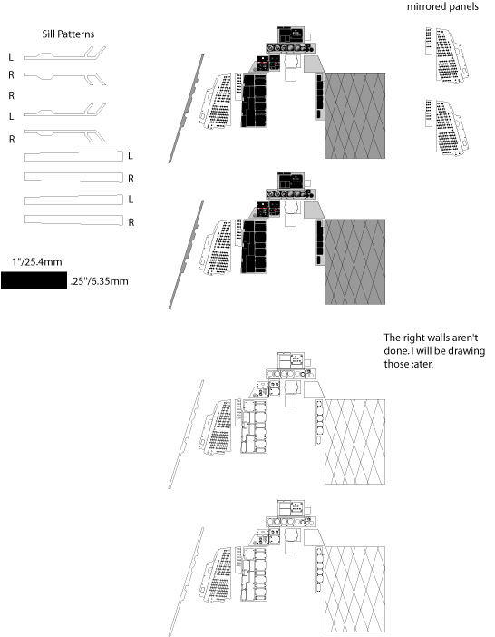
Well, I tried to save the above pic and then look at it and it stank! So If anyone wants it, just let me know and I will send the file. But remember, all of the cockpits in different versions of the Phantom were different, so this only really applies to the -4B. The sills and inner sill are still the same though. Pete
-
Shoot! I posted before I saw your new post. I will send you an AI drawing. I think Corel can opn vector graphics? Aw heck, here are the drawings as they are now. This is a Jpeg I added the black rectangle for scale. I will still send a copy to anyone who wants it. I print onto cardstock and can use that as a template. Another trick is to print onto label paper (adhesive-backed) and then cut that out and stic it. Let's see how this comes out...
-
Stusbke, I'd be glad to send you a copy. What graphics programs do you have? I can send a vector drawing, which will be the cleanest, which is good in this small size. Or, I can send a JPEG . Either way, I will include a scale on the drawing to make sure you can print it the right size. Now if I could just do my own photo-etching Pete
-
WOOHOO! After 3 tries, I finaly made a breaker panel I am happy with. It was the easiest method of the three. I printed the pattern in a mirror image and DST (double-sided tape)'d it to the back of the sheet. Then I used the alignment method shown in the earlier post to punch the dots with a needle in a pin vise. I put the panel on a few pieces of paper so that the breakers would raise when I used the needle. I have to say that without LSP, I don't know if I would be doing the extra work to really make this thing that little extra bit better. Thanks Guys, Pete

-
Hahaha! Oh Stusbke! Pete