

GunnarO
-
Posts
35 -
Joined
-
Last visited
Content Type
Profiles
Forums
Events
Posts posted by GunnarO
-
-
Hi Peter
You've got this, which slightly differ from the information you have already. This is from the P-51 B/C Parts list. There were probably more than one version of the seat, the parts list have two.
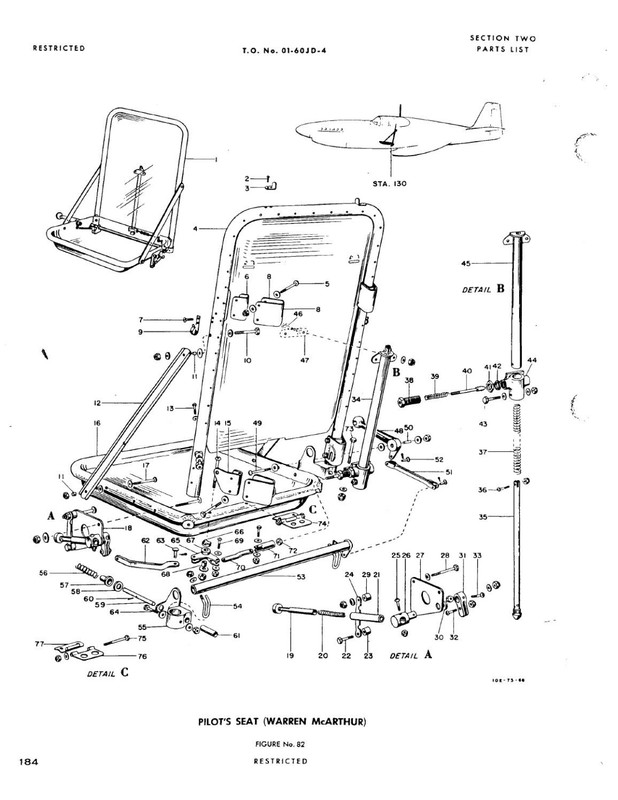
If you look at the P-51 D/K Parts list, you'll find this:
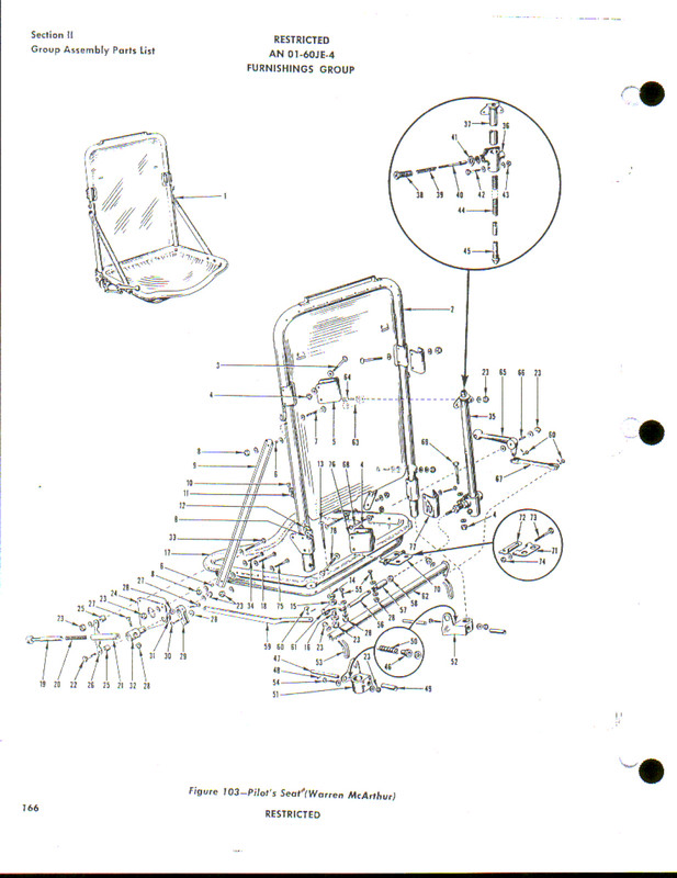
Cheers
-
Here is the tyre for the Mustang if you want to buy a new one today.
On the drawing it is a Goodyear 24 x 7.7 tyre. Which by the way is the same size as used on the Boeing 737.
But if this is the right pattern is hard to say. The image looks mostly like the cross pattern.
Cheers
Gunnar
-
-
I'm afraid the project is put on hold due to ongoing research on the full size Whirlwind. There are still some areas that needs attention, and the underside of the fuselage with the recess for the flap is one of them. That's currently where the model is too. I'll continue as soon as I figure out the structure and details in that area.
In the meantime, I've started another 1/24 scale print of a rather obscure Soviet fighter prototype..... Stay tuned...
Cheers
-
Hi Nick

I dont doubt anything you say. So lets analyse this
Anyone starting out in 3D printing will be using PLA - so firstly its the easy the common choice.
as to alternative choices - well ABS might be slightly better - but I think the fragility issue would be an issue no matter what the material.
This build is not meant to be something that requires you to be a very advanced modeler - hopefully - I mean I myself am only starting out with 3D and with 3D design.
The choice of topic is not really intended to make life difficult - but yet at the same time maybe offer something a little out of the ordinary.
Which means that its worth trying - and if I fail - I just adjust slightly and try again till we have an easy process.
I can already tell you that there is no way i would be able to lift a framework off the printer bed - if the framework was 1mm, 2mm or such like.
Thats fine - it just means we have to print with some thin material in between - in other words print it as if we are printing the covering along with the framework.
Now we already know that wont look like material covering so we can still cover over that on the outside with thin material for a scale look.
Thats more or less my thinking at this stage. Im sure many aspects will get tweaked as we go along - or maybe we change topics. Its ok - all part of the learning curve
My confidence is only in that there is no reason not to try - not that the end result will be a showstopper - so lets see how it turns out.
I still make blunders on plastic models and ive been building them for 44 years, Im sure i will blunder with 3D
I'd suggest you try printing with HIPS. It's Polystyrene so normal glue can be used and it is easy to sand and cut. Stronger than PLA but not so hard surface. I've got a Prusa i3 MK2S and can give you pointers for setup etc. If you use 0.4mm extruder, use 0.45mm walls. (I always use 0.05mm wider walls for the thinnest parts) Normal wall thickness should be 1.5 - 2mm for strong rigid walls. I print mostly 0.1mm layers at slow speed, makes the best details and the surface look good.
My Whirlwind project is currently on hold due to project research, but I have started a new one that probably will be posted here in the near future. I started with PLA, but moved on to HIPS. I'll never go back. If you want to check it out: http://forum.largescaleplanes.com/index.php?showtopic=71157&hl=whirlwind
There's a nice thread about 3D printing as well : http://forum.largescaleplanes.com/index.php?showtopic=70571
Cheers
-
-
Long time since posting, and in the meantime lots of problems with printing polystyrene.
Long story short, Z axis adjustment lost after a firmware upgrade without being noticed....
 I've finally managed to dial in all the HIPS and printer settings and can move on with the project. During all the tests, I've concluded that printing it like a normal kit is not the best way to go. I'm now trying to print it in bits and pieces and glue them together. (well, that's basically what a "normal" kit is also....
  - Larger bits and pieces...) This way I can print the whole rear fuselage as one solid part without seams. Looks very promising. And print bed adhesion is not a problem anymore once I got the Z axis properly adjusted.

This is current status for the new parts:

Cheers
- Trak-Tor, Hubert Boillot, Shawn M and 5 others
-
 8
8
-
-
I think the 85% does help with the perspective of the task since you are shooting fairly high but will realistically have to settle for less. Not even sure a lot of personalities can work with this dynamic. You have to fool yourself into thinking you can do anything and then only later tell yourself it's OK to fail (a little). Perfectionists can give this a try but unless they can also deal with a significant failure rate they are very likely to give up in frustration (and worse their standards are so high that they "fail" a lot) . I'd probably categorize myself as a hard working dreamer who at times comes down from the clouds. The more I work though the better I am and fewer trips down. It quite addictive that way. Much like golf I suppose.
I'll watch for that thread. But by all means share the journey in any form.
That's a good advice, Jim.
I always want to put all the details I can get into the model. But, If I ever want to finish it, I have to remove and simplify a lot. I ask myself "what will be visible on the finished model" quite often, and have started to make the 3D model based on that. (This relates mostly to 3D modeling/3D printing) So, on the Whirlwind I'm making, I've left the elevators attached to the tailplane since it's not important to me if I can move them on the finished model. This leads to a simplified hinge based on what's visible, like this:

Because, when I've put on the litho plates for covering the model, this is what's visible:

So, no one can see if the bearings are missing...
This is my 85%. I do deeply admire those that put all the details in and make all the control surfaces and landing gears movable, but I'm good with doing things this way and I have a lot better chance of finish it some day than loose myself in details...
Cheers
-
Moving along...
First complete print with HIPS. After a LOT of trail and error, the first complete print is finished. It's not all good, I have some delamination of the layers. I know however how to fix it, so the top part of the tailplane is tuned in during the print. I think I have the settings ready now, will start a new one tomorrow to check my theories.

The surface quality of the HIPS is remarkably good. Comparing to the first print I did with PLA, it's a no-brainer what to use...


Adding to that, the HIPS is much easier to cut, file and sand and I can use my old Humbrol liquid glue
Cheers
- LSP_Kevin, Cees Broere, Starfighter and 2 others
-
5
-
Some excellent stuff! I never imagined in my lifetime that someone could print out their own model.
I have to ask: What is the difference between litho plate and a sheet of aluminum?
Gaz
Hey Gaz,
They are basicly the same, except the litho plates have been used in the offset printing industry. The litho plates are 0,15mm and I got 10 A4 sheets for £12. Arts and crafts stores have some painted aluminium sheets with the same thickness, but they are £3-4 each. Pure Aluminium foil is much more expensive, a sheet of 0,15x150x150mm is £200. (at least the ones I found...)
Cheers
-
Thanks guys!
I got the litho plates on eBay https://www.ebay.com/itm/Aluminium-Litho-Plates-for-Model-Building-pack-of-10-A4-size/391925485031?hash=item5b40944de7:g:9IMAAOSwRvdZaTPC
The rivets were done one by one on freehand with a ruler, so a little dodgy... going to use a finer rivet tool and a template with denser rivet pattern on the model. Got the rivet tool from UMM-USA: http://umm-usa.com/onlinestore/product_info.php?cPath=21_22&products_id=1322
Cheers
-
Should have added use the glue stick also sorry
, if the brims not work go with the raft, you can use the glue stick for about 2 or 3 prints then you need to clean the glass with water and re apply.Thanks, Rick! I'll try that on the next one. This one didn't work out either, but I got more of it...


The deep V between the tailplane and the elevator is something I wanted to test. I think I'll leave the elevator attached, so I cut back the tailplane a little to make room for the part of the elevator that's inside the tailplane. I then will use litho plate as skin, and extend it over the V to lie flush with the elevator. hopefully it will look good when finished.
Then I thought I could use the parts as a test bed for puting on litho plates. The really nice thing with the surface quality of the print is that I don't need to fill and sand anything, I just glue the litho plates on top of the print.
Sorry for the glue mess, I said it was just a test...

And then the tailplane skin over front part of the elevator.


ok then, more fine tuning of the printer settings...
Cheers
-
nice rigid solution, takes alignment out of the equation!
Thanks, yes it works very well.
Hey Gunnar, look at our 3d-printing thread:
http://forum.largescaleplanes.com/index.php?showtopic=70571&page=2
I had the same problems with HIPS not sticking on the plate, and finally bought this special foil called Buildtak. It's available in various sizes. And I'm not exaggerating when I say that for me, it's difference like day and night. Especially the very first few prints on this foil were sticking so good on the plate that it wasn't easy to remove the parts. I use a box cutter blade to carefully remove the parts. After some prints, the adhesion is getting weaker, but it is still much better than printing on the glass plate. Highly recommended.
Cheers
Alex
Thanks Alex, I've read through the thread already. The bed on my printer can't be switched out. The heating plate is covered with a PEI film glued to the plate. It works quite good. The new printer model has a replaceable heat plate of metal, so I might upgrade at a later point.
I cant stress enough the use of a raft or brim when your printing. gives the print a much wider base to the plate.
Yes, I used an 8mm brim but it still didn't work. I'm trying now with a glue stick, and it seem to work. I turned the print 90 degrees on the plate as well, don't know if it helps but tried it anyway.
Cheers
-
FINALLY!!! a roll of HIPS is in the house.
First print was perfect, better quality than the PLA parts and easy to work with. Cutting and filing was just plain easy. My favorite material so far. I started with a small part for mounting the tailplane together, and went on to do the tailplanes.
Then the problems begun...
The following prints would not stick to the plate, so I'm still trying different methods for keeping them stuck. I guess it is the warping that lifts them, so just need to find the right stuff to fix it.
The quality of the parts though, is just great. Looking forward to see how the parts turns out when I find the right solution.
The cross for mounting the tailplane and part of port tailplane:

The hole in the tailplane parts have a 0,1mm clearance, and slides perfecly on to the mounting cross:

Mounted together, it's a perfect fit.

On to the next test....
Cheers
- Alburymodeler, Sparzanza, sandokan and 4 others
-
7
-
I Love your work and explanation of what you're doing. I am now following this thread!
I've been working with TinkerCAD, teaching myself how to create the 3D models of what I will want to build when I do buy a printer. STEEP learning curve, fortunately, i'm doing the design leaning before committing to the purchase....keeps my mind occupied.
LOVE the work you're doing
Cheers
Dan
Thanks, Dan!
A very capable CAD package is Fusion 360 from Autodesk. It has all the tools you need for modeling an aircraft and direct export to a slicer software like Cura or PreForm. It has a free license for "enthusiasts", which we are....
Software download: https://www.autodesk.com/products/fusion-360/free-trial
License information: https://knowledge.autodesk.com/support/fusion-360/troubleshooting/caas/sfdcarticles/sfdcarticles/How-to-activate-start-up-or-educational-licensing-for-Fusion-360.html
Great work so far

Currently, I like HIPS best for that kind of projects, too. Easy to glue, sand and scribe.
Cheers
Alex
Thanks, Alex!
Good to get a second confirmation on the decision to use HIPS. Got a shipment confirmation today, so won't be long before next print is running.
Cheers
-
HIPS is all I use, I find that ABS as to many warping issues when you printing thin wall and PLA was ok but for what we want to do its not useful.
You will find with HIPS and a raft you can print 90 degree vertical.
This is good news!
Thanks.Can you share some print settings you find works best on your printer? like printing temp., heat bed temp., printing speed, etc.
I've found the glue that works best for PLA is Selley's Plastic Fix. You get a primer pen that you apply to one surface, and a superglue gel. Normal superglue just doesn't have the same bonding power.
Thanks! I suspected this was the case. For the moment I'll try out prints with HIPS and see if I can use D-Limonene as glue, or maybe normal plastic kit glue will work.
Cheers
-
I jus dun a silly thing..... I bought a Formlabs 2!
Freaking amazing! Considering the original machine I learned on 15 years ago set my employers back £110,000, and it needed 50kg of resin loaded into it before it would build a single thing, it is amazing how technology has moved on.
Someone still has to do the CAD though......
Great printer, good luck with it. I wish I could afford one, it's excellent for detail work. For my work though, I figured out I could order a lot of parts from shapeways for the price of one and bought my Prusa i3.
So, a little progress. Cleaned up the parts and taped them together. Tailplane is done as well.

I think I'll call this a proof of concept. The experience so far with PLA is quite good, but the material is hard and brittle when printing this thin. It is also quite hard to sand and a little difficult to glue. I tried CA, but maybe I didn't use the right type because I could quite easy break the parts up again. I thought maybe I should use epoxy glue to join the parts instead, but haven't tried it yet.
After a good deal of thinking, the obvious thing occured to me. I should print the parts with polystyrene, It's what I'm used to working with and what most model kits are made of...
A roll of HIPS (High Impact PolyStyrene) filament is on order. It has the same good mechanical properties as ABS, but prints as easy as PLA. Hopefully it will turn out more usefull and a better choise for printing modelkits than the PLA I've used so far. New tests will follow and more CAD work to be done in the meantime.
Cheers
- Harrison90, Sparzanza, sandokan and 8 others
-
11
-
The fuselage of the S6 was built the same way as the S5, with just a different spacing and number of ribs. Unfortunately, I haven't been able to get S5 drawings yet, but the surface detail of the S6 can be seen here:

And the ribs:

Cheers
- BradG, sandokan, Leaning_Dog and 3 others
-
6
-
The surface details seems very coarse, I'll see if I can dig up some more details this afternoon. I have collected some drawings that are quite detailed.
The Profile Publications gives a good description of the wings and radiator system, you can find a copy of it here: https://rclibrary.co.uk/files_titles/1861/Profile_039_Supermarine_S4-S6B.pdf

Cheers
-
After a roll of filament that didn't work out well, I've finaly made some progress. Some hours has gone into the model as well, so I was quite excited to see if things worked out with this one. The fuselage is divided in two, due to the length, and in two halves like a normal kit. I printed the model halves in a 40 degree angle and the rear part also turned 60 degrees around the first angle. I was very pleased it turned out well after 22,5 hours print time. I printed with a layer hight of 0,1mm so I could use it for the final model in case it went well.

A few supports were printed as well, but the most important one was modelled as a stiffening rib between the base and the model. The large base was to ensure it would stick to the building plate.

It's easier to see the angle on the rear fuselage here.

A bit of cleaning up...

And it's starting to look a bit like a Whirlwind
 A 1:48 scale Classic Airframes Whirlwind for comparison.
Cheers
-
Some nice reference photos here: http://www.gettyimages.co.uk/photos/supermarine-s.5?excludenudity=false&mediatype=photography&phrase=supermarine%20s.5&sort=mostpopular#license
Although a different search, many S.5 photos turn up. For a cockpit image, I guess the S.6 is quite similar: http://www.gettyimages.co.uk/photos/supermarine-s.6?excludenudity=false&mediatype=photography&phrase=supermarine%20s.6&sort=mostpopular#license
A nice in flight shot: https://www.thisdayinaviation.com/tag/napier-lion-w-12/
Some videos:
I know that Cambridge University Library holds a few original engineering drawings of the S.5, but only some outlines and GA's.
Cheers
-
Hi Torben,
Looking forward to see this one finished. It's difficult to find good references, especially from the cockpit. A very nice piece is the article from Flight magazine February 1928. Here's a PDF copy: https://www.jottacloud.com/p/gunnaro/a1508d4e1b444bd58b4eb09b4e920e59
I'll see if I can dig out some more, the S5 is one of my favorites
Cheers
-
Impressive start Juraj! Looking forward to see the rest of the build.
Cheers

 Great job and an outstanding model Kev.
 just like me... Look forward to your next project already.
1/18 P51C Mustang "Lopes Hope the 3rd"
in Works in Progress
Posted · Edited by GunnarO
Hi Peter,
Not sure if you've seen this, but good description of the seats. Seems the T6 Harvard/Texan used the same seat.
http://warbirdinformationexchange.org/phpBB3/viewtopic.php?f=3&t=65446
If this is correct, the straight edge seat was used up to P-51D-5-NA
And as a curiosity, Here is the Warren McArthur's patent for one of their bucket seats.
https://patentimages.storage.googleapis.com/1c/69/4e/f7097215ef3be3/US2291247.pdf
Cheers