

JayW
-
Posts
1,952 -
Joined
-
Last visited
-
Days Won
19
Reputation Activity
-

 JayW got a reaction from Greg W in 1/18 Scale Blue Box F4U-1A Corsair Modification
Let me update my task list for the wings (crossed out items are complete):
1. Wing attach concept development, and incorporation (will not install wings until later)
2. Inboard end wing skinning
3. Represent gun camera and approach lights inside the wing, if I can.
4. Improve outboard flaps, skin with aluminum and simulated fabric, install.
5. Fab, install lower surface flap gap doors
5A. Fab and install fixed trailing edge aileron hinge fittings.
6. Paint entire wing minus ailerons (double hairspray method on aluminum leading edge panels and access doors, Navy blue on top, intermediate blue on bottom, including the great big stars and bars insignias). Also decals and weathering.
7. Miscellaneous details (tear drop ID light, fuel tank caps, fab and dry fit pitot mast, etc).
8. Prepare (including paint) and install ailerons oriented at approximately 10 deg up and down.
9. Fab and install and paint currently missing upper surface spanwise skin strips just forward of the ailerons (Too fragile to install earlier).
Actually this list helps me keep my mind in the game. Note I added item 5A - "Fab and install fixed trailing edge aileron hinge fittings."
OK - the gun camera. Ha!! This is the first model I have ever built where I actually made a gun camera. Why? Because the Corsair has a window in front of it in the wing leading edge, allowing it to be seen. Most other aircraft I have seen just have a small dark hole where the camera can't be seen. Lookie -
First, if I did not separate the lower and upper wing halves (recall I just couldn't get them apart), how did I get the gun camera (or the approach light you saw last post) inside? By dremmeling a big hole into the inboard end of the wing:
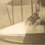
A conveniently located post is in there, where I could crudely attach the camera, and also the approach light, such that they are properly oriented. Here is the gun camera in the wing (upside down):
Then the skinning could begin, including the little window:
Upside down again.... See the camera in there? Oh yes.
Then it was on to the outboard flaps. Here is one of them unmodified except some sanding:
This flap is primarily fabric covered in real life (the other flaps are fully covered in aluminum sheet metal). Except the leading edge, and that little access door you see on top at the inboard end just behind the leading edge panel. They are aluminum. That door, no doubt, has to be the access provision for disconnecting the flap, allowing it to hang down to afford improved access to the 50 cal's. We discussed this some in a previous post and TAG provided great pictures.
Here, I have treated this device like the outboard wing, rudder, and elevators - skin using .005 inch thick plastic sheet for the fabric areas, and skin the other areas in .005 aluminum.
Lower surface (note - more drain holes):
And upper surface with the hinged access door:
An abbreviated leading edge skin awaits installation after the flap is attached to the wing. Like this:
A bit of a milestone - outboard flap attachment to the wing. Again I am very happy with the look of the fabric-covered surfaces. Hope you all like it too.
Once the flaps were attached (glued/epoxied) to the wings, it was time to add the outboard flap outboard hinge support:
It is important to me, because that fitting provides the attach lug for the aileron balance tab control rod (that little white tab sticking out). Yup - that's actually how it is in real life. You will see what I am talking about before too long. At this location, Vought chose not to cover the dropped hinge point with a fairing, as was done at all the other flap hinge locations (save at the side of body where the flap support is actually inside the fuselage). Instead both the wing side and flap side hinge fittings are somewhat aerodynamically shaped, and left to dangle in the airstream on their own. But then, the Corsair aficionado knows all this! I tried to duplicate that.
OK, it is now on to the lower surface flap gap doors, and the outboard flap inboard hinge fairing, which I 3D printed a while back. Then aileron supports. The wings are coming along folks. Stay tuned!
-
JayW got a reaction from Greg W in 1/18 Scale Blue Box F4U-1A Corsair Modification
Last post I released a list of wing tasks to complete the wings. Here is where I am so far:
1. Wing attach concept development, and incorporation (will not install wings until later)
2. Inboard end wing skinning
3. Represent gun camera and approach lights inside the wing, if I can.
4. Improve outboard flaps, skin with aluminum and simulated fabric, install.
5. Fab, install lower surface flap gap doors
6. Paint entire wing minus ailerons (double hairspray method on aluminum leading edge panels and access doors, Navy blue on top, intermediate blue on bottom, including the great big stars and bars insignias). Also decals and weathering.
7. Miscellaneous details (tear drop ID light, fuel tank caps, fab and dry fit pitot mast, etc).
8. Prepare (including paint) and install ailerons oriented at approximately 10 deg up and down.
9. Fab and install and paint currently missing upper surface spanwise skin strips just forward of the ailerons (Too fragile to install earlier).
Wing attach concept - The wings as is have little tabs on their inboard ends that engage slots in the wing center section. Great for properly locating the wings; wholly inadequate for gluing them on. I need more things to add structural strength to the join. So I got out the dremmel and butchered the ends to allow for some structure:
What a mess! Two "spar" stubs that fit in matching slots I dremmeled. Wish they were longer, but the wheel bay ribs are right there not far from the join. And three pins that engage matching holes I drilled. I use the term "matching" loosely. It was hard to match them up perfectly; it is not perfect. Those features augment the already existing tabs that you should be able to see. All that, plus a heap of glue/epoxy/CA and maybe I will have strong wing joins. Hope so; not much else I can do.
Then I took a shot at the approach light and its opening on the LH wing, which is part of the wing skinning. The openings were already there - one of the first things I did for the wings a couple months ago. A tricky aluminum skin was made:
A crude light was glued inside the wing, a small piece of .005 inch thick clear plastic sheet added, that aluminum skin, and you get this:
Hmmm - in that view you cannot see the light box. It can be seen easily though from other views. I'll take it. The toy had nothing there at all.
In order to skin the inboard end of the wing with a minimum of ugly gaps, I needed to first establish the dihedral before trimming the various skin panels. I made some tools to check this angle. First, I needed something to orient the aircraft in a horizontal position:
The model is simply resting on its brake drums and the new jack under the tail gear. Then I made a crude locating fixture that bears up against the wing lower surface:
The outboard wings are supposed to have a 8.5 degree dihedral angle measured at the wing reference plane. That turns out to be about 10 deg measured along the lower wing surface at the main spar (because of its tapered thickness), and that is what that locating fixture reflects. That looks right to me. Comments?
What I found is that the toy has less dihedral than that - probably more like 6 deg. Maybe less - hard to tell it is so floppy. This orientation with correct dihedral results in a tight fit at the join on top of the wing (almost no gap at all), and a substantial gap on the bottom. So what I intend to do is to provide extra material on my lower aluminum panels and trim to minimize or eliminate that gap. It is easier said than done.
Here is the LH wing with all of the inboard skinning done. Me likes:
Much of this wing fold area is fictional - 21st Century Toys (or Bluebox) did a poor job of replicating it, and I never took the time or effort to try to correct. Few will notice methinks. Those lower panels are oversized and, as I mentioned, must be trimmed to fit - a very laborious task that will involve a whole lot of handling this large unwieldy and fragile model. Already I broke a landing gear door hinge fitting - AGAIN!
It would make life easier in some ways if I could just glue the wings on right now. But more must be done, and the painting would be near impossible; I would much rather finish and paint the outboard wings separately, so that is what I am going to do.
Now - the RH wing needs to be brought up to snuff, including the gun camera and its opening. Then that lower panel trimming will commence. And then, next on the list is outboard flaps. Stay tuned - adventures ahead.
-
JayW got a reaction from Greg W in 1/18 Scale Blue Box F4U-1A Corsair Modification
I am very very pleased to show off my simulated fabric skin bays for the wings, upper and lower surfaces. They have been fully prepared, using masking and layers of primer to simulate doubler fabric, and the strips that go over the rib caps. Also a few drain hole grommets have been added to the lower panels.
Upper surfaces:
Lower surfaces:
Drain hole grommets (lower surface):
Lower ID lights and more drain hole grommets:
Upper surface formation light, upper ID light base, and the hand hold plate:
Don't look now, but these wings are almost entirely skinned. All that remains are the narrow skins at the wing fold (inboard ends), and the long skin strips just forward of the ailerons (upper surface), which will go on last due to they're being quite fragile. The inboard skins will be tough because they will surround the gun camera opening on one wing and the approach light on the other.
But first, it is now time to figure out how I am going to firmly attach these wings to the center section. The toy came with a spindly contraption that allowed the wings to fold and at the same time was a means of attachment, along with some alignment tabs. The wing fold contraptions are long gone, the tabs remain and I will use them. So for years now I have been kicking the can down the road, not bothering to think about it much. Now is the time. I can't just glue them; that isn't robust enough. Stay tuned for the next post - I am formulating a plan for a robust attachment and will show it.
For those impatient to see these wings done and installed (I am!!), here is a list of what remains, roughly in order:
1. Wing attach concept development, and incorporation (will not install wings until later)
2. Inboard end wing skinning
3. Represent gun camera and approach lights inside the wing, if I can.
4. Improve outboard flaps, skin with aluminum and simulated fabric, install.
5. Fab, install lower surface flap gap doors
6. Paint entire wing minus ailerons (double hairspray method on aluminum leading edge panels and access doors, Navy blue on top, intermediate blue on bottom, including the great big stars and bars insignias). Also decals and weathering.
7. Miscellaneous details (tear drop ID light, fuel tank caps, fab and dry fit pitot mast, etc).
8. Prepare (including paint) and install ailerons oriented at approximately 10 deg up and down.
9. Fab and install and paint currently missing upper surface spanwise skin strips just forward of the ailerons (Too fragile to install earlier).
Then it will be time to attach the wings. Should be a month or six weeks or so.....
-
 JayW got a reaction from daHeld in 1/18 Scale Blue Box F4U-1A Corsair Modification
That would be the F4U-1C. A big design change for sure. Lots of parts affected. It appears to get the same flap assembly with the missing leading edge chunk. It gets a new lower surface flap gap hinged door - one piece which spans the whole flap, as opposed to the normal two doors separated by a fixed "bucket" which provides the hollow for the outboard '50. It is that fixed bucket that causes that chunk to be taken away from the flap. So no hollow for the -1C. The cannon installation drawing shows the outboard 20 mm on about the same centerline as the outboard .50. But the aft end of the 20mm does not protrude into the flap. The gun barrels extend forward of the wing leading edge, and are staggered.
I found a -1C outboard flap skeleton assembly drawing which shows a leading edge nearly intact (just a shallow chunk missing). But it appears to be an orphan drawing, apparently that version of outboard flap didn't get built? Because the wing assembly drawing for the -1C calls for a normal -1A outboard flap. So looks like there was a plan to modify the flap to get restore the flap leading edge, but it fell through.... Business decision I guess.
That being the case, we now have a flap with a missing chunk of leading edge, and a flap gap hinged door that provides a nice big slot for air to travel from lower surface to upper surface.
-
JayW got a reaction from Greg W in 1/18 Scale Blue Box F4U-1A Corsair Modification
No update yet - soon. Instead an item of interest where I invite comments.
As I was building the wing trailing edge devises, I noticed right off the F4U has a compromised outboard flap. A large section of its leading edge is missing:
A section through the missing area:
My flap doesn't have this cutout in it; it is covered up by the wing when the flap is retracted, so completely unseen.
When the flap is deployed though, this missing section of flap is in full view and in the airstream. A local loss of lift results as can be seen in this view:
Due to the local compromised airfoil shape, flow separation will occur on the upper surface of the deployed flap, and the separation will take on somewhat of a fan shape as I depict in blue. It appears to me that up to 25% of the lift capability of that flap is gone. In my professional employment in the airplane company, I learned much about trailing edge devise aerodynamics, especially flaps. If low speed approach and/or deck length limited takeoffs are critical, you need alot of flap to develop high lift at those low speeds, if you are limited on total wing area. The Corsair has alot of flap. You do not need a lift loss like you see above. No sir.
So why is it that way? It is that way because the outboard gun butt end clashes with the flap (if not for the cutout):
I circled in red where the clash would be. Note in that last picture how deep inside the wing the guns are. That's why the F4U leading edge has those zombie eyes holes in it three per side. As is typical of just about any aircraft with multiple gun arrangements in the wings, the guns are staggered so as to allow feeding of the ammunition. But what is not typical is that the gun barrels are buried deep inside the wing. The F4U's sister ship the F6F Hellcat has its -50's staggered as well, but the barrel tips are all forward of the leading. That is also true of the P-47 Thunderbolt. The P-51 has its gun tips just barely forward of the wing leading edge but there is practically no stagger. Instead the P-51 ammo chutes (some of them) are designed to run on top of one another after a fashion. None of these other contemporary American aircraft have guns that compromise the trailing edge devises like that.
So why again? Why are the Corsair's guns placed so far aft?
I don't know but I can postulate. The Corsair is the only aircraft among those I list to have a wing leading edge fuel tank (I show it a couple of pics above in red outline). At least the first versions. The -1D's and subsequent did not have the integral leading edge tank; instead they had the duel wing pylons which could carry large jettisonable tanks. Note the leading edge tank is just outboard of the guns. But fuel lines occupy the same bay as the gun barrels and blast tubes. I'll bet guns placed further forward like the Hellcat were incompatible in some way with that leading edge fuel tank and its system runs. Anybody know for sure?
Whatever the case, that is a serious design compromise to cut a section of leading edge away from your precious flap. Lower stall speeds and take-off speeds would be had if that flap had 100% of its lift capability. If it were because of that fuel tank, how ironic it is that it went away with the -1D's..... The -1D's were saddled with a limited lift outboard flap for what amounts to no reason at all!
I would remind that with flaps up, the wing is clean - that missing portion is covered. So no issue at high speed. Any Corsair experts out there care to chime in on this rather unfortunate design compromise?
-
JayW reacted to MikeMaben in 1/18 Scale Blue Box F4U-1A Corsair Modification
That was the basis of my diagnosis. It was a trade-off they had no choice but to make.
-
 JayW got a reaction from Paulpk in 1/18 Scale Blue Box F4U-1A Corsair Modification
I am very very pleased to show off my simulated fabric skin bays for the wings, upper and lower surfaces. They have been fully prepared, using masking and layers of primer to simulate doubler fabric, and the strips that go over the rib caps. Also a few drain hole grommets have been added to the lower panels.
Upper surfaces:
Lower surfaces:
Drain hole grommets (lower surface):
Lower ID lights and more drain hole grommets:
Upper surface formation light, upper ID light base, and the hand hold plate:
Don't look now, but these wings are almost entirely skinned. All that remains are the narrow skins at the wing fold (inboard ends), and the long skin strips just forward of the ailerons (upper surface), which will go on last due to they're being quite fragile. The inboard skins will be tough because they will surround the gun camera opening on one wing and the approach light on the other.
But first, it is now time to figure out how I am going to firmly attach these wings to the center section. The toy came with a spindly contraption that allowed the wings to fold and at the same time was a means of attachment, along with some alignment tabs. The wing fold contraptions are long gone, the tabs remain and I will use them. So for years now I have been kicking the can down the road, not bothering to think about it much. Now is the time. I can't just glue them; that isn't robust enough. Stay tuned for the next post - I am formulating a plan for a robust attachment and will show it.
For those impatient to see these wings done and installed (I am!!), here is a list of what remains, roughly in order:
1. Wing attach concept development, and incorporation (will not install wings until later)
2. Inboard end wing skinning
3. Represent gun camera and approach lights inside the wing, if I can.
4. Improve outboard flaps, skin with aluminum and simulated fabric, install.
5. Fab, install lower surface flap gap doors
6. Paint entire wing minus ailerons (double hairspray method on aluminum leading edge panels and access doors, Navy blue on top, intermediate blue on bottom, including the great big stars and bars insignias). Also decals and weathering.
7. Miscellaneous details (tear drop ID light, fuel tank caps, fab and dry fit pitot mast, etc).
8. Prepare (including paint) and install ailerons oriented at approximately 10 deg up and down.
9. Fab and install and paint currently missing upper surface spanwise skin strips just forward of the ailerons (Too fragile to install earlier).
Then it will be time to attach the wings. Should be a month or six weeks or so.....
-
JayW reacted to Oldbaldguy in 1/18 Scale Blue Box F4U-1A Corsair Modification
Considering the configuration, the likely question put to the guys who would fly the thing in combat was: “You all want six .50s and 85 knots over the ramp or four .50s and 80 knots over the ramp? You can’t have both.” Being good Naval Aviators and fighter pilots, most probably said they wanted eight .50s and 100 knots over the ramp but nobody would let them do that so they went with six. Anybody know if the Corsairs with four 20mm had that flap interference issue? Looks like the only reason the cutout is there is to accommodate that outboard gun and the only reason that gun is where it is, is to make room for the feed trays for the other guns. There was only so much room inside the wing and something had to give, so they put the guns where they needed to, cut a hole in the flap to make everything fit and hoped no one would notice. And nobody much did until Jay pointed it out!
-
 JayW got a reaction from CODY in 1/18 Scale Blue Box F4U-1A Corsair Modification
No update yet - soon. Instead an item of interest where I invite comments.
As I was building the wing trailing edge devises, I noticed right off the F4U has a compromised outboard flap. A large section of its leading edge is missing:
A section through the missing area:
My flap doesn't have this cutout in it; it is covered up by the wing when the flap is retracted, so completely unseen.
When the flap is deployed though, this missing section of flap is in full view and in the airstream. A local loss of lift results as can be seen in this view:
Due to the local compromised airfoil shape, flow separation will occur on the upper surface of the deployed flap, and the separation will take on somewhat of a fan shape as I depict in blue. It appears to me that up to 25% of the lift capability of that flap is gone. In my professional employment in the airplane company, I learned much about trailing edge devise aerodynamics, especially flaps. If low speed approach and/or deck length limited takeoffs are critical, you need alot of flap to develop high lift at those low speeds, if you are limited on total wing area. The Corsair has alot of flap. You do not need a lift loss like you see above. No sir.
So why is it that way? It is that way because the outboard gun butt end clashes with the flap (if not for the cutout):
I circled in red where the clash would be. Note in that last picture how deep inside the wing the guns are. That's why the F4U leading edge has those zombie eyes holes in it three per side. As is typical of just about any aircraft with multiple gun arrangements in the wings, the guns are staggered so as to allow feeding of the ammunition. But what is not typical is that the gun barrels are buried deep inside the wing. The F4U's sister ship the F6F Hellcat has its -50's staggered as well, but the barrel tips are all forward of the leading. That is also true of the P-47 Thunderbolt. The P-51 has its gun tips just barely forward of the wing leading edge but there is practically no stagger. Instead the P-51 ammo chutes (some of them) are designed to run on top of one another after a fashion. None of these other contemporary American aircraft have guns that compromise the trailing edge devises like that.
So why again? Why are the Corsair's guns placed so far aft?
I don't know but I can postulate. The Corsair is the only aircraft among those I list to have a wing leading edge fuel tank (I show it a couple of pics above in red outline). At least the first versions. The -1D's and subsequent did not have the integral leading edge tank; instead they had the duel wing pylons which could carry large jettisonable tanks. Note the leading edge tank is just outboard of the guns. But fuel lines occupy the same bay as the gun barrels and blast tubes. I'll bet guns placed further forward like the Hellcat were incompatible in some way with that leading edge fuel tank and its system runs. Anybody know for sure?
Whatever the case, that is a serious design compromise to cut a section of leading edge away from your precious flap. Lower stall speeds and take-off speeds would be had if that flap had 100% of its lift capability. If it were because of that fuel tank, how ironic it is that it went away with the -1D's..... The -1D's were saddled with a limited lift outboard flap for what amounts to no reason at all!
I would remind that with flaps up, the wing is clean - that missing portion is covered. So no issue at high speed. Any Corsair experts out there care to chime in on this rather unfortunate design compromise?
-
 JayW got a reaction from scvrobeson in 1/18 Scale Blue Box F4U-1A Corsair Modification
No update yet - soon. Instead an item of interest where I invite comments.
As I was building the wing trailing edge devises, I noticed right off the F4U has a compromised outboard flap. A large section of its leading edge is missing:
A section through the missing area:
My flap doesn't have this cutout in it; it is covered up by the wing when the flap is retracted, so completely unseen.
When the flap is deployed though, this missing section of flap is in full view and in the airstream. A local loss of lift results as can be seen in this view:
Due to the local compromised airfoil shape, flow separation will occur on the upper surface of the deployed flap, and the separation will take on somewhat of a fan shape as I depict in blue. It appears to me that up to 25% of the lift capability of that flap is gone. In my professional employment in the airplane company, I learned much about trailing edge devise aerodynamics, especially flaps. If low speed approach and/or deck length limited takeoffs are critical, you need alot of flap to develop high lift at those low speeds, if you are limited on total wing area. The Corsair has alot of flap. You do not need a lift loss like you see above. No sir.
So why is it that way? It is that way because the outboard gun butt end clashes with the flap (if not for the cutout):
I circled in red where the clash would be. Note in that last picture how deep inside the wing the guns are. That's why the F4U leading edge has those zombie eyes holes in it three per side. As is typical of just about any aircraft with multiple gun arrangements in the wings, the guns are staggered so as to allow feeding of the ammunition. But what is not typical is that the gun barrels are buried deep inside the wing. The F4U's sister ship the F6F Hellcat has its -50's staggered as well, but the barrel tips are all forward of the leading. That is also true of the P-47 Thunderbolt. The P-51 has its gun tips just barely forward of the wing leading edge but there is practically no stagger. Instead the P-51 ammo chutes (some of them) are designed to run on top of one another after a fashion. None of these other contemporary American aircraft have guns that compromise the trailing edge devises like that.
So why again? Why are the Corsair's guns placed so far aft?
I don't know but I can postulate. The Corsair is the only aircraft among those I list to have a wing leading edge fuel tank (I show it a couple of pics above in red outline). At least the first versions. The -1D's and subsequent did not have the integral leading edge tank; instead they had the duel wing pylons which could carry large jettisonable tanks. Note the leading edge tank is just outboard of the guns. But fuel lines occupy the same bay as the gun barrels and blast tubes. I'll bet guns placed further forward like the Hellcat were incompatible in some way with that leading edge fuel tank and its system runs. Anybody know for sure?
Whatever the case, that is a serious design compromise to cut a section of leading edge away from your precious flap. Lower stall speeds and take-off speeds would be had if that flap had 100% of its lift capability. If it were because of that fuel tank, how ironic it is that it went away with the -1D's..... The -1D's were saddled with a limited lift outboard flap for what amounts to no reason at all!
I would remind that with flaps up, the wing is clean - that missing portion is covered. So no issue at high speed. Any Corsair experts out there care to chime in on this rather unfortunate design compromise?
-
JayW reacted to Oldbaldguy in 1/18 Scale Blue Box F4U-1A Corsair Modification
Look at a plan view of the airplane. All the heavy items - guns, ammo, gas - are on the CG, causing the airplane to feel/fly the same whether you are at gross or are landing on fumes - the pilot does not have to continuously fiddle with the trim. The guns are staggered in order to get everything - guns, feed troughs, etc - to fit inside the relatively thin outer wing panels. The notch in the flap is probably less of an issue than you estimate. It is there to accommodate the aft end of the offending .50 that protrudes into the flap well. The notch, while appearing large, is sealed at the leading edge and therefor produces less drag than an open hole and still produces lift. Airflow behind it may be a little turbulent, but I doubt there was a complete loss of lift aft of the notch. These are simple hinged flaps with gap seals all around. They do not increase wing area; all they do is change the camber of the airfoil to make it more efficient at low speeds. The notch isn’t much exposed to the airflow until the flaps are fully down, at which point they are producing more drag than lift anyway. With six gaping gun ports located right on the leading edge, and two whopping big oil cooler vents essentially flattening the leading edge of the wing root section, a relatively small notch in the leading edge of one flap is small potatoes. At least that is how it looks to me.
-
JayW reacted to easixpedro in 1/18 Scale Blue Box F4U-1A Corsair Modification
You said it yourself! Everything in aero-engineering is a compromise. Throw in a bunch of NavAir requirements to fit in the hangar deck, elevator, stout landing gear for slamming on the deck, you name it.
Probably came from something as simple as having to be able to access the guns and load it while on deck as your previous posts have shown. Some draftsman probably was really proud of his work and then a manager came in and gave him another set if requirements...grab another cup of Joe and back to the literal drawing board. And he was happy to get it to only 25% loss. There was a war on and I can only imagine the number of airframe changes they dealt with on a daily basis.
My .02 worth and all...
-
JayW reacted to MikeMaben in 1/18 Scale Blue Box F4U-1A Corsair Modification
Since flaps control 2 functions, lift and drag, it's possible there was enough
of both that they could afford the loss 25% of both to accomodate the guns.
The only thing I can think of that might affect the staggered placement of
the guns could be the length/tapered cord thickness of the outboard wing
due to the location of the wing fold.
-
JayW reacted to geedubelyer in 1/18 Scale Blue Box F4U-1A Corsair Modification
I'm making a wild guess but I'd think centre of gravity.
That's a very larger engine hanging way out in front of the wing. Maybe the guns had to be so far back to compensate a little?
-
 JayW got a reaction from Derek B in 1/18 Scale Blue Box F4U-1A Corsair Modification
No update yet - soon. Instead an item of interest where I invite comments.
As I was building the wing trailing edge devises, I noticed right off the F4U has a compromised outboard flap. A large section of its leading edge is missing:
A section through the missing area:
My flap doesn't have this cutout in it; it is covered up by the wing when the flap is retracted, so completely unseen.
When the flap is deployed though, this missing section of flap is in full view and in the airstream. A local loss of lift results as can be seen in this view:
Due to the local compromised airfoil shape, flow separation will occur on the upper surface of the deployed flap, and the separation will take on somewhat of a fan shape as I depict in blue. It appears to me that up to 25% of the lift capability of that flap is gone. In my professional employment in the airplane company, I learned much about trailing edge devise aerodynamics, especially flaps. If low speed approach and/or deck length limited takeoffs are critical, you need alot of flap to develop high lift at those low speeds, if you are limited on total wing area. The Corsair has alot of flap. You do not need a lift loss like you see above. No sir.
So why is it that way? It is that way because the outboard gun butt end clashes with the flap (if not for the cutout):
I circled in red where the clash would be. Note in that last picture how deep inside the wing the guns are. That's why the F4U leading edge has those zombie eyes holes in it three per side. As is typical of just about any aircraft with multiple gun arrangements in the wings, the guns are staggered so as to allow feeding of the ammunition. But what is not typical is that the gun barrels are buried deep inside the wing. The F4U's sister ship the F6F Hellcat has its -50's staggered as well, but the barrel tips are all forward of the leading. That is also true of the P-47 Thunderbolt. The P-51 has its gun tips just barely forward of the wing leading edge but there is practically no stagger. Instead the P-51 ammo chutes (some of them) are designed to run on top of one another after a fashion. None of these other contemporary American aircraft have guns that compromise the trailing edge devises like that.
So why again? Why are the Corsair's guns placed so far aft?
I don't know but I can postulate. The Corsair is the only aircraft among those I list to have a wing leading edge fuel tank (I show it a couple of pics above in red outline). At least the first versions. The -1D's and subsequent did not have the integral leading edge tank; instead they had the duel wing pylons which could carry large jettisonable tanks. Note the leading edge tank is just outboard of the guns. But fuel lines occupy the same bay as the gun barrels and blast tubes. I'll bet guns placed further forward like the Hellcat were incompatible in some way with that leading edge fuel tank and its system runs. Anybody know for sure?
Whatever the case, that is a serious design compromise to cut a section of leading edge away from your precious flap. Lower stall speeds and take-off speeds would be had if that flap had 100% of its lift capability. If it were because of that fuel tank, how ironic it is that it went away with the -1D's..... The -1D's were saddled with a limited lift outboard flap for what amounts to no reason at all!
I would remind that with flaps up, the wing is clean - that missing portion is covered. So no issue at high speed. Any Corsair experts out there care to chime in on this rather unfortunate design compromise?
-
 JayW got a reaction from Landrotten Highlander in 1/18 Scale Blue Box F4U-1A Corsair Modification
No update yet - soon. Instead an item of interest where I invite comments.
As I was building the wing trailing edge devises, I noticed right off the F4U has a compromised outboard flap. A large section of its leading edge is missing:
A section through the missing area:
My flap doesn't have this cutout in it; it is covered up by the wing when the flap is retracted, so completely unseen.
When the flap is deployed though, this missing section of flap is in full view and in the airstream. A local loss of lift results as can be seen in this view:
Due to the local compromised airfoil shape, flow separation will occur on the upper surface of the deployed flap, and the separation will take on somewhat of a fan shape as I depict in blue. It appears to me that up to 25% of the lift capability of that flap is gone. In my professional employment in the airplane company, I learned much about trailing edge devise aerodynamics, especially flaps. If low speed approach and/or deck length limited takeoffs are critical, you need alot of flap to develop high lift at those low speeds, if you are limited on total wing area. The Corsair has alot of flap. You do not need a lift loss like you see above. No sir.
So why is it that way? It is that way because the outboard gun butt end clashes with the flap (if not for the cutout):
I circled in red where the clash would be. Note in that last picture how deep inside the wing the guns are. That's why the F4U leading edge has those zombie eyes holes in it three per side. As is typical of just about any aircraft with multiple gun arrangements in the wings, the guns are staggered so as to allow feeding of the ammunition. But what is not typical is that the gun barrels are buried deep inside the wing. The F4U's sister ship the F6F Hellcat has its -50's staggered as well, but the barrel tips are all forward of the leading. That is also true of the P-47 Thunderbolt. The P-51 has its gun tips just barely forward of the wing leading edge but there is practically no stagger. Instead the P-51 ammo chutes (some of them) are designed to run on top of one another after a fashion. None of these other contemporary American aircraft have guns that compromise the trailing edge devises like that.
So why again? Why are the Corsair's guns placed so far aft?
I don't know but I can postulate. The Corsair is the only aircraft among those I list to have a wing leading edge fuel tank (I show it a couple of pics above in red outline). At least the first versions. The -1D's and subsequent did not have the integral leading edge tank; instead they had the duel wing pylons which could carry large jettisonable tanks. Note the leading edge tank is just outboard of the guns. But fuel lines occupy the same bay as the gun barrels and blast tubes. I'll bet guns placed further forward like the Hellcat were incompatible in some way with that leading edge fuel tank and its system runs. Anybody know for sure?
Whatever the case, that is a serious design compromise to cut a section of leading edge away from your precious flap. Lower stall speeds and take-off speeds would be had if that flap had 100% of its lift capability. If it were because of that fuel tank, how ironic it is that it went away with the -1D's..... The -1D's were saddled with a limited lift outboard flap for what amounts to no reason at all!
I would remind that with flaps up, the wing is clean - that missing portion is covered. So no issue at high speed. Any Corsair experts out there care to chime in on this rather unfortunate design compromise?
-
JayW reacted to airscale in 1/32 Douglas TBD-1 Devastator by Trumpeter - TBD-1A in October 2023!
I have some of that coming in a few weeks...
news here
pre orders here
hope it hits the spot
Peter
-
 JayW got a reaction from Ironwing in 1/18 Scale Blue Box F4U-1A Corsair Modification
Moving right along, ticking things off the list -
1. Wing attach concept development, and incorporation (will not install wings until later)
2. Inboard end wing skinning
3. Represent gun camera and approach lights inside the wing, if I can.
4. Improve outboard flaps, skin with aluminum and simulated fabric, install.
5. Fab, install lower surface flap gap doors
5A. Fab and install fixed trailing edge aileron hinge fittings.
6. Paint entire wing minus ailerons (double hairspray method on aluminum leading edge panels and access doors, Navy blue on top, intermediate blue on bottom, including the great big stars and bars insignias). Also decals and weathering.
7. Miscellaneous details (tear drop ID light, fuel tank caps, fab and dry fit pitot mast, etc).
8. Prepare (including paint) and install ailerons oriented at approximately 10 deg up and down.
9. Fab and install and paint currently missing upper surface spanwise skin strips just forward of the ailerons (Too fragile to install earlier).
Not all in order as you can see. I moved item 9 up - that skin strip has to be there before the wing gets painted.
Lower surface flap gap doors. I think most of you know that Corsairs have flat panels just forward of the flaps on the wing lower surface, on simple hinges. These panels rotate into the wing as the flaps deploy, covering the fixed trailing edge cove and providing a fairly clean gap for airflow up and around the flap nose. I created these parts on the inboard wings; now it was time to do same for the outboard wings:
There are two per flap - I added brass hinge pins for them. The other panels are fixed.
Also, with those lower panels in place, I could install the last of the flap hinge fairings:
That part was Rhino modelled and 3D printed. By yours truly. I like my 3D printer!
Next was aileron hinge fittings:
Very tedious, not very impressive as you see them - just various chunks of plastic carefully located to match the hinge fittings on the aileron itself. But next post or the one after you will see how they support the ailerons, and I think you will like it.
Next was that pesky aluminum gap cover strip on the upper surface just forward of the aileron. You can see it in this full view of the wing upper surface:
That view shows a wing ready for paint. Here is the lower surface just for grins:
Next time you see the wings they will be in some stage of painting. The aluminum surfaces will get the double hair spray treatment on top of a clear coat (this worked pretty well on the aft fuselage). No etching primer. That way I can chip away at the leading edge like I did for the inboard wing - only not as much. The outboard wings were out of the prop wash. Also, lots of wear around the gun bays, where I will consult various pictures, and the time capsule Corsair book.
I am pretty pumped about the wing progress. Stay tuned!
-
 JayW got a reaction from rafju in 1/18 Scale Blue Box F4U-1A Corsair Modification
Let me update my task list for the wings (crossed out items are complete):
1. Wing attach concept development, and incorporation (will not install wings until later)
2. Inboard end wing skinning
3. Represent gun camera and approach lights inside the wing, if I can.
4. Improve outboard flaps, skin with aluminum and simulated fabric, install.
5. Fab, install lower surface flap gap doors
5A. Fab and install fixed trailing edge aileron hinge fittings.
6. Paint entire wing minus ailerons (double hairspray method on aluminum leading edge panels and access doors, Navy blue on top, intermediate blue on bottom, including the great big stars and bars insignias). Also decals and weathering.
7. Miscellaneous details (tear drop ID light, fuel tank caps, fab and dry fit pitot mast, etc).
8. Prepare (including paint) and install ailerons oriented at approximately 10 deg up and down.
9. Fab and install and paint currently missing upper surface spanwise skin strips just forward of the ailerons (Too fragile to install earlier).
Actually this list helps me keep my mind in the game. Note I added item 5A - "Fab and install fixed trailing edge aileron hinge fittings."
OK - the gun camera. Ha!! This is the first model I have ever built where I actually made a gun camera. Why? Because the Corsair has a window in front of it in the wing leading edge, allowing it to be seen. Most other aircraft I have seen just have a small dark hole where the camera can't be seen. Lookie -
First, if I did not separate the lower and upper wing halves (recall I just couldn't get them apart), how did I get the gun camera (or the approach light you saw last post) inside? By dremmeling a big hole into the inboard end of the wing:
A conveniently located post is in there, where I could crudely attach the camera, and also the approach light, such that they are properly oriented. Here is the gun camera in the wing (upside down):
Then the skinning could begin, including the little window:
Upside down again.... See the camera in there? Oh yes.
Then it was on to the outboard flaps. Here is one of them unmodified except some sanding:
This flap is primarily fabric covered in real life (the other flaps are fully covered in aluminum sheet metal). Except the leading edge, and that little access door you see on top at the inboard end just behind the leading edge panel. They are aluminum. That door, no doubt, has to be the access provision for disconnecting the flap, allowing it to hang down to afford improved access to the 50 cal's. We discussed this some in a previous post and TAG provided great pictures.
Here, I have treated this device like the outboard wing, rudder, and elevators - skin using .005 inch thick plastic sheet for the fabric areas, and skin the other areas in .005 aluminum.
Lower surface (note - more drain holes):
And upper surface with the hinged access door:
An abbreviated leading edge skin awaits installation after the flap is attached to the wing. Like this:
A bit of a milestone - outboard flap attachment to the wing. Again I am very happy with the look of the fabric-covered surfaces. Hope you all like it too.
Once the flaps were attached (glued/epoxied) to the wings, it was time to add the outboard flap outboard hinge support:
It is important to me, because that fitting provides the attach lug for the aileron balance tab control rod (that little white tab sticking out). Yup - that's actually how it is in real life. You will see what I am talking about before too long. At this location, Vought chose not to cover the dropped hinge point with a fairing, as was done at all the other flap hinge locations (save at the side of body where the flap support is actually inside the fuselage). Instead both the wing side and flap side hinge fittings are somewhat aerodynamically shaped, and left to dangle in the airstream on their own. But then, the Corsair aficionado knows all this! I tried to duplicate that.
OK, it is now on to the lower surface flap gap doors, and the outboard flap inboard hinge fairing, which I 3D printed a while back. Then aileron supports. The wings are coming along folks. Stay tuned!
-
JayW got a reaction from rafju in 1/18 Scale Blue Box F4U-1A Corsair Modification
Last post I released a list of wing tasks to complete the wings. Here is where I am so far:
1. Wing attach concept development, and incorporation (will not install wings until later)
2. Inboard end wing skinning
3. Represent gun camera and approach lights inside the wing, if I can.
4. Improve outboard flaps, skin with aluminum and simulated fabric, install.
5. Fab, install lower surface flap gap doors
6. Paint entire wing minus ailerons (double hairspray method on aluminum leading edge panels and access doors, Navy blue on top, intermediate blue on bottom, including the great big stars and bars insignias). Also decals and weathering.
7. Miscellaneous details (tear drop ID light, fuel tank caps, fab and dry fit pitot mast, etc).
8. Prepare (including paint) and install ailerons oriented at approximately 10 deg up and down.
9. Fab and install and paint currently missing upper surface spanwise skin strips just forward of the ailerons (Too fragile to install earlier).
Wing attach concept - The wings as is have little tabs on their inboard ends that engage slots in the wing center section. Great for properly locating the wings; wholly inadequate for gluing them on. I need more things to add structural strength to the join. So I got out the dremmel and butchered the ends to allow for some structure:
What a mess! Two "spar" stubs that fit in matching slots I dremmeled. Wish they were longer, but the wheel bay ribs are right there not far from the join. And three pins that engage matching holes I drilled. I use the term "matching" loosely. It was hard to match them up perfectly; it is not perfect. Those features augment the already existing tabs that you should be able to see. All that, plus a heap of glue/epoxy/CA and maybe I will have strong wing joins. Hope so; not much else I can do.
Then I took a shot at the approach light and its opening on the LH wing, which is part of the wing skinning. The openings were already there - one of the first things I did for the wings a couple months ago. A tricky aluminum skin was made:
A crude light was glued inside the wing, a small piece of .005 inch thick clear plastic sheet added, that aluminum skin, and you get this:
Hmmm - in that view you cannot see the light box. It can be seen easily though from other views. I'll take it. The toy had nothing there at all.
In order to skin the inboard end of the wing with a minimum of ugly gaps, I needed to first establish the dihedral before trimming the various skin panels. I made some tools to check this angle. First, I needed something to orient the aircraft in a horizontal position:
The model is simply resting on its brake drums and the new jack under the tail gear. Then I made a crude locating fixture that bears up against the wing lower surface:
The outboard wings are supposed to have a 8.5 degree dihedral angle measured at the wing reference plane. That turns out to be about 10 deg measured along the lower wing surface at the main spar (because of its tapered thickness), and that is what that locating fixture reflects. That looks right to me. Comments?
What I found is that the toy has less dihedral than that - probably more like 6 deg. Maybe less - hard to tell it is so floppy. This orientation with correct dihedral results in a tight fit at the join on top of the wing (almost no gap at all), and a substantial gap on the bottom. So what I intend to do is to provide extra material on my lower aluminum panels and trim to minimize or eliminate that gap. It is easier said than done.
Here is the LH wing with all of the inboard skinning done. Me likes:
Much of this wing fold area is fictional - 21st Century Toys (or Bluebox) did a poor job of replicating it, and I never took the time or effort to try to correct. Few will notice methinks. Those lower panels are oversized and, as I mentioned, must be trimmed to fit - a very laborious task that will involve a whole lot of handling this large unwieldy and fragile model. Already I broke a landing gear door hinge fitting - AGAIN!
It would make life easier in some ways if I could just glue the wings on right now. But more must be done, and the painting would be near impossible; I would much rather finish and paint the outboard wings separately, so that is what I am going to do.
Now - the RH wing needs to be brought up to snuff, including the gun camera and its opening. Then that lower panel trimming will commence. And then, next on the list is outboard flaps. Stay tuned - adventures ahead.
-
 JayW got a reaction from Thunnus in 1/32 Hasegawa Ki-61 Tei Hien
John - what a convincing paint job. You may have told me before - do you sand down any rough paint edges after masking? If you do, what do you use?
-
JayW reacted to Thunnus in 1/32 Hasegawa Ki-61 Tei Hien
Thanks guys! I initially saw this scheme on a Hasegawa box top and thought that it was a cool scheme that I don't commonly see. Plus, it happened to be a Tei variant, of which I had the Wolf Pack conversion... easy choice!
Markings have been tweaked and massaged. At this point, the major painting is complete so let's take a look at her in the light box...
Clear coat and decals are next!
-
JayW reacted to Thunnus in 1/32 Hasegawa Ki-61 Tei Hien
Thanks Matt! LSP is a great source for new ideas and techniques. Almost everything that I do here has been learned from someone else's expertise.
Thanks so much Jay! I wish we could get paid for slinging paint like NFL quarterbacks get for throwing footballs!
Some lessons learned from the port side, I went ahead and tried the Sentai markings on the starboard side of the tail. The most critical thing was getting the dangling portions of the mask into the correct position. The Oramask material can stretch and distort, especially on uneven surfaces, so I'm trying to minimize the distortion.
Once the main mask is secured into place, the white is sprayed.
The thin outline mask is then put into position. The inner mask has two parts and I use tape to keep those two parts together. It's easier to place these two into place than the skinny border only. After positioning the two parts within the outline mask, the inner mask is removed, leaving just the border piece. Micro Mask is used to seal any gaps between the two mask parts.
Then the blue is sprayed. It's important to give adequate time for the paint to dry between mask applications. That was probably one of the reasons the port side came out a little ragged. I'm always fighting my inclination to move quickly but luckily, these acrylic-lacquers dry quickly.
Patience netted a much cleaner result on the starboard side.
A white stripe was added between the tail and hinomaru.
The last major marking to be painted is the blue/white diagonal sash. Instead of pre-cut masks, I used strips of Tamiya tape to establish the outline of the sash. This is painted white.
After the white is dry, I cut thin strips of Tamiya tape and masked the borders of the stripe. Instead of Micro Mask, it was easier to seal the joints with more strips of tape. The blue is then sprayed.
Ok... so the major markings are just about done.
I'm going to do some touch-up work and then we'll seal the markings with a gloss coat and apply some small decals.
-
JayW got a reaction from scvrobeson in 1/32 Hasegawa Ki-61 Tei Hien
Uh - NOT far from perfect. Only to the best model painter in the world (or in the top five!).
-
JayW got a reaction from Thunnus in 1/32 Hasegawa Ki-61 Tei Hien
Uh - NOT far from perfect. Only to the best model painter in the world (or in the top five!).